2009 SUBARU TRIBECA instrument panel
[x] Cancel search: instrument panelPage 11 of 2453

AB-12
Inspection Locations After a Collision
AIRBAG SYSTEM
3. Inspection Locations After a
Collision
A: REPLACEMENT
Replace the following parts when the airbag is de-
ployed.
1. FRONT COLLISION
1) Driver’s airbag module
2) Passenger’s airbag module
3) Driver’s seat belt (Pretensioner)
4) Passenger’s seat belt (Pretensioner)
5) Airbag control module
6) Front sub sensor (L/R)
7) Roll connector
8) Instrument panel (for integrating with passen-
ger’s airbag module)
9) Passenger side seat cushion pad and frame as-
sembly
2. SIDE COLLISION
1) Airbag control module
2) Side airbag module (operating side seat back-
rest)
3) Side airbag sensor (operating side)
4) Curtain airbag module (operating side)
5) Curtain airbag sensor (operating side)
3. INSPECTION OF OTHER PARTS
Check for the following parts, and replace the dam-
aged parts with new parts.
1) Steering wheel and steering shaft
Check the steering shaft for mounting conditions
and deflection of front and rear, upward and down-
ward directions, and deflection of front and rear di-
rection with tilt lever released. (After a collision,
there is a good chance that the shock absorbing
part of steering shaft may have operated.)
2) Check the connectors of airbag module, preten-
sioner, etc. for damage, and also check each har-
ness for pinch and connector damage. Replace the
harness as a unit if damage is found.
3) Check the seat cushion frame, backrest, seat rail
and headrest for deformation, distortion, crack, and
installing condition and play.
4) For passengers seat, replace the seat cushion
frame assembly with new one if the seat cushion
frame is deformed or cracked.
5) If there are tears or loosening in the passenger
side seat cushion cover, it may interfere with the
proper operation of the passenger detection sys-
tem. Replace with a new cushion cover.
6) Be sure to perform the system calibration for the
occupant detection system after removing or re-
placing the passenger seat cushion cover. Failure
to do so may cause improper operation of the pas-
senger detection system.
TION, Subaru Select Monitor.>
7) Use the Subaru Select Monitor to check whether
the drivers seat position sensor and the drivers and
the front left/right seat belt buckle switches are op-
erating normally.
B: INSPECTION
If the vehicle is involved in a collision, even if it is a
slight collision, be sure to check the following sys-
tems.
1. DRIVER’S AIRBAG MODULE
1) Check for the following, and replace the dam-
aged parts with new parts.
•Airbag module is cracked or deformed.
•Harness and/or connector is cracked, deformed
or open. Harness wire is exposed.
•The module surface is fouled with grease, oil,
water or cleaning solvent.
2) When installing a new driver’s airbag module,
check for the following, and replace the damaged
parts with new parts.
•The steering wheel is in the way, making it diffi-
cult to install the airbag module.
•The clearance between the driver’s airbag mod-
ule and steering wheel is not constant.
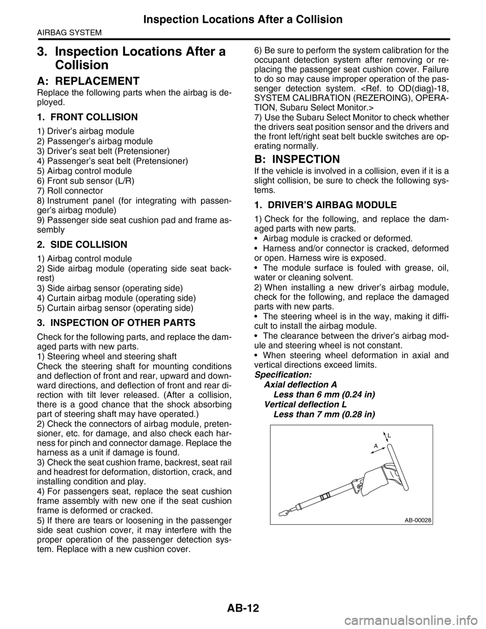
•When steering wheel deformation in axial and
vertical directions exceed limits.
Specification:
Axial deflection A
Less than 6 mm (0.24 in)
Vertical deflection L
Less than 7 mm (0.28 in)
AB-00028
L
A
Page 12 of 2453

AB-13
Inspection Locations After a Collision
AIRBAG SYSTEM
2. PASSENGER’S AIRBAG MODULE
Check for the following, and replace the damaged
parts with new parts.
•Airbag module and instrument panel are cracked
or deformed.
•Harness and/or connector is cracked, deformed
or open. Harness wire is exposed.
•Mounting bracket is cracked or deformed.
3. SIDE AIRBAG MODULE
Check for the following, and replace the damaged
parts with new parts.
•Front seat, airbag module and mounting bracket
are damaged or deformed.
•Harness and/or connector is cracked, deformed
or open. Harness wire is exposed.
4. CURTAIN AIRBAG MODULE
Check for the following, and replace the damaged
parts with new parts.
•Airbag cover is scratched or broken.
•Harness and/or connector is cracked, deformed
or open. Harness wire is exposed.
•Mounting bracket and securing clip are cracked
or deformed.
5. AIRBAG CONTROL MODULE
Check for the following, and replace the damaged
parts with new parts.
•Control module is cracked or deformed.
•Mounting bracket is cracked or deformed.
•Connector is scratched, cracked or deformed.
•Airbag is deployed.
•Side airbag is deployed.
•Curtain airbag is deployed.
6. FRONT SUB SENSOR
If the section of vehicle as shown in the figure is
damaged, check the following items and replace
the damaged parts with new parts.
•Front sub sensor is cracked or deformed.
•Mounting bracket is cracked or deformed.
•Connector is scratched, cracked or deformed.
•Airbag is deployed.
7. SIDE AIRBAG SENSOR AND CURTAIN
AIRBAG SENSOR
If the section of vehicle as shown in the figure is
damaged, check the following items and replace
the damaged parts with new parts.
•Side airbag sensor and curtain airbag sensor are
cracked or deformed.
•Mounting bracket is cracked or deformed.
•Connector is scratched, cracked or deformed.
•Side airbag or curtain airbag is deployed. (oper-
ating side)
8. ROLL CONNECTOR
Check for the following, and replace the damaged
parts with new parts.
•Combination switch or steering roll connector is
cracked or deformed.
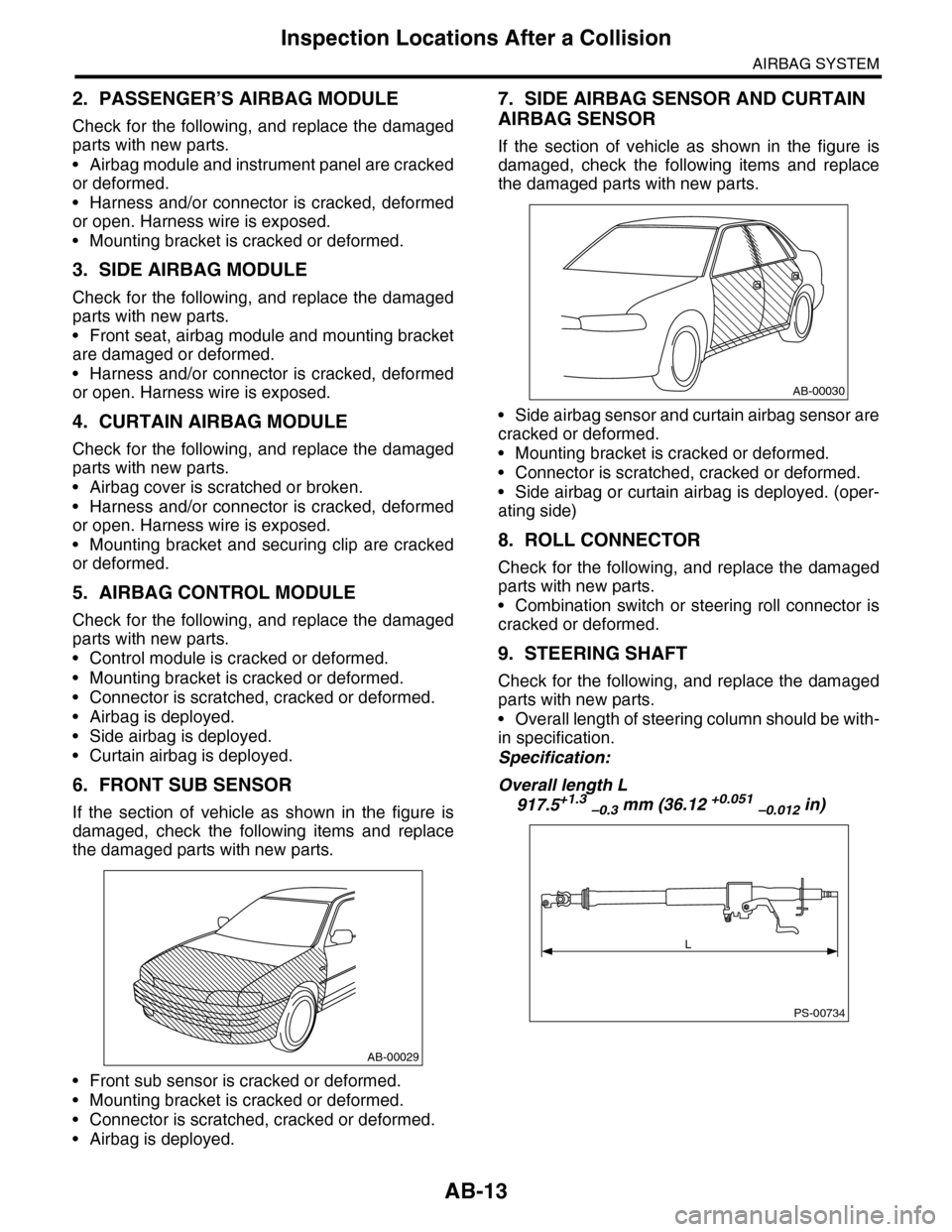
9. STEERING SHAFT
Check for the following, and replace the damaged
parts with new parts.
•Overall length of steering column should be with-
in specification.
Specification:
Overall length L
917.5+1.3 –0.3 mm (36.12 +0.051 –0.012 in)
AB-00029
AB-00030
PS-00734
L
Page 15 of 2453

AB-16
Passenger’s Airbag Module
AIRBAG SYSTEM
5. Passenger’s Airbag Module
A: REMOVAL
CAUTION:
Refer to “CAUTION” of “General Description”
before handling the airbag module.
1) Turn the ignition switch to OFF.
2) Disconnect the ground cable from battery and
wait for at least 20 seconds before starting work.
3) Remove the glove box.
4) Remove the mounting bolts of the passenger’s
side air bag module.
5) Remove the instrument panel upper.
Instrument Panel Assembly.>
6) Remove the screws, and remove the passen-
ger’s airbag module.
7) Refer to “CAUTION” for handling of a removed
airbag module.
B: INSTALLATION
CAUTION:
Refer to “CAUTION” of “General Description”
before handling the airbag module.
Install in the reverse order of removal.
Tightening torque:
7.4 N·m (0.75 kgf-m, 5.5 ft-lb)
C: INSPECTION
CAUTION:
Refer to “CAUTION” of “General Description”
before handling the airbag module.
Check for the following, and replace the damaged
parts with new parts.
•Airbag module, harness, connector and mount-
ing bracket are damaged.
Inspection Locations After a Collision.>
EI-01327
AB-01276
Page 20 of 2453

AB-21
Airbag Control Module
AIRBAG SYSTEM
8. Airbag Control Module
A: REMOVAL
CAUTION:
•Do not disassemble the airbag control mod-
ule.
•If the airbag control module is deformed or if
the fault occurs by water, replace the airbag
control module with a new one.
•Do not drop the airbag control module.
•After removal, keep the airbag control mod-
ule on a dry, clean surface away from moisture,
heat and dust.
1) Turn the ignition switch to OFF.
2) Disconnect the ground cable from battery and
wait for at least 20 seconds before starting work.
3) Remove the center console.
4) Remove the console box.
5) Remove the instrument panel lower cover.
er.>
6) Remove the glove box.
7) Remove the audio unit.
8) Remove the screws, and remove the center con-
sole frame.
9) Disconnect the connector from airbag control
module.
10) Remove the bolts and remove airbag control
module.
B: INSTALLATION
CAUTION:
•Do not reuse the bolt and nut.
•Always use new bolts and nuts for them.
•Be sure to put the water protection cover
over the connector.
Install in the reverse order of removal.
Tightening torque:
25 N·m (2.5 kgf-m, 18.1 ft-lb)
C: INSPECTION
Check for the following, and replace the damaged
parts with new parts.
•Control module, connector, and mounting brack-
et are damaged.
•Airbag is deployed.
•Side airbag is deployed.
•Curtain airbag is deployed.
AB-01280
AB-00759
Page 55 of 2453

AB(diag)-31
Subaru Select Monitor
AIRBAG SYSTEM (DIAGNOSTICS)
7. Subaru Select Monitor
A: OPERATION
1. READ DIAGNOSTIC TROUBLE CODE
(DTC)
When malfunction of airbag system occurs, the
DTC stored in airbag control module will be read
out.
1) Prepare the Subaru Select Monitor kit.
TOOL, General Description.>
2) Connect the diagnosis cable to Subaru Select
Monitor.
3) Insert the cartridge to Subaru Select Monitor.
4) Connect the Subaru Select Monitor to data link
connector.
(1) Data link connector (1) is located in the low-
er portion of instrument panel (on the driver’s
side).
(2) Connect the diagnosis cable to data link
connector.
CAUTION:
Do not connect the scan tools except for Suba-
ru Select Monitor.
5) Turn the ignition switch to ON (engine OFF) and
turn the Subaru Select Monitor switch to ON.
6) On the «Main Menu» display screen, select the
{Each System Check} and press the [YES] key.
7) On the «System Selection Menu» display
screen, select the {Airbag System} and press the
[YES] key.
8) {Press the [YES] key after the {**MY AIRBAG
SYSTEM} is displayed.
9) On the «Airbag System» screen, select the
{DTC Display}, and then press the [YES] key.
NOTE:
•For details concerning operation procedure, re-
fer to the “SUBARU SELECT MONITOR OPERA-
TION MANUAL”.
•For details concerning DTCs, refer to List of Di-
agnostic Trouble Code (DTC).
ABS00111
ABS00112
EN-03693
(1) Power switch
ABS00114
(1)
Page 65 of 2453

AB(diag)-41
Airbag Warning Light Failure
AIRBAG SYSTEM (DIAGNOSTICS)
Step Check Yes No
1READ DTC.
Read the DTC.
OPERATION, Subaru Select Monitor.>
Is DTC displayed? Perform the diag-
nosis according to
DTC.
Go to step 2.
2CHECK POOR CONTACT.
1) Turn the ignition switch to OFF, disconnect
the battery ground cable, and wait more than
20 seconds.
2) Confirm that there is solid connection
between the airbag control module and con-
nector (AB6).
Is there poor contact in con-
nector (AB6)?
If the poor contact
of the connector is
not fixed, replace
the airbag main
harness with body
harness or replace
the airbag control
module.
Control Module.>
Go to step 3.
3CHECK AIRBAG MAIN HARNESS.
1) Remove the instrument panel lower cover
and disconnect the connectors (AB7) and
(AB2).
2) Remove the console side cover lower on
the passenger's side and disconnect the con-
nectors (AB10) and (AB9).
3) Disconnect the connector (AB6) from air-
bag control module, and connect the connector
(1U) in the test harness U.
4) Connect the battery ground terminal and
turn the ignition switch to ON.
5) Connect the connectors (7U) and (8U) in
the test harness U.
NOTE:After the fault has been cleared, disconnect the
connectors (7U) and (8U).
Does the airbag warning light
go off?
Go to step 4.Go to step 5.
4CHECK GROUND CIRCUIT.
1) Turn the ignition switch to OFF, disconnect
the battery ground cable, and wait more than
20 seconds.
2) Disconnect the connector (AB6) from air-
bag control module.
3) Connect the connector (1U) in the test har-
ness U to body harness connector (AB6).
4) Measure the resistance between connector
(2U) in the test harness U and chassis ground.
Connector & terminal
(2U) No. 10 — Chassis ground:
(2U) No. 11 — Chassis ground:
Is the resistance less than 10
Ω?
Replace the airbag
control module.
Module.>
Repair the chas-
sis ground circuit.
5CHECK AIRBAG MAIN HARNESS AND
BULKHEAD HARNESS.
1) Disconnect the connectors (7U) and (8U).
2) Remove the combination meter.
3) Measure the resistance between connector
(i11) and connector (2U) in the test harness U.
Connector & terminal
(2U) No. 7 — (i11) No. 12:
Is the resistance less than 10
Ω?
Check the combi-
nation meter.
Go to step 6.
Page 75 of 2453

AB(diag)-51
Diagnostic Chart with Trouble Code
AIRBAG SYSTEM (DIAGNOSTICS)
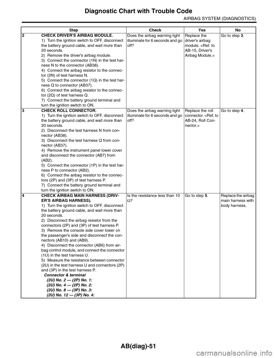
2CHECK DRIVER'S AIRBAG MODULE.
1) Turn the ignition switch to OFF, disconnect
the battery ground cable, and wait more than
20 seconds.
2) Remove the driver’s airbag module.
3) Connect the connector (1N) in the test har-
ness N to the connector (AB38).
4) Connect the airbag resistor to the connec-
tor (2N) of test harness N.
5) Connect the connector (1Q) in the test har-
ness Q to connector (AB37).
6) Connect the airbag resistor to the connec-
tor (2Q) of test harness Q.
7) Connect the battery ground terminal and
turn the ignition switch to ON.
Does the airbag warning light
illuminate for 6 seconds and go
off?
Replace the
driver's airbag
module.
Airbag Module.>
Go to step 3.
3CHECK ROLL CONNECTOR.
1) Turn the ignition switch to OFF, disconnect
the battery ground cable, and wait more than
20 seconds.
2) Disconnect the test harness N from con-
nector (AB38).
3) Disconnect the test harness Q from con-
nector (AB37).
4) Remove the instrument panel lower cover
and disconnect the connector (AB7) from
(AB2).
5) Connect the connector (1P) in the test har-
ness P to connector (AB2).
6) Connect the airbag resistor to the connec-
tors (2P) and (3P) of test harness P.
7) Connect the battery ground terminal and
turn the ignition switch to ON.
Does the airbag warning light
illuminate for 6 seconds and go
off?
Replace the roll
connector.
nector.>
Go to step 4.
4CHECK AIRBAG MAIN HARNESS (DRIV-
ER'S AIRBAG HARNESS).
1) Turn the ignition switch to OFF, disconnect
the battery ground cable, and wait more than
20 seconds.
2) Disconnect the airbag resistor from the
connectors (2P) and (3P) of test harness P.
3) Remove the console side cover lower on
the passenger's side and disconnect the con-
nectors (AB10) and (AB9).
4) Disconnect the connector (AB6) from air-
bag control module, and connect the connector
(1U) in the test harness U.
5) Measure the resistance between connector
(2U) in the test harness U and connectors (2P)
and (3P) in the test harness P.
Connector & terminal
(2U) No. 2 — (2P) No. 1:
(2U) No. 4 — (2P) No. 2:
(2U) No. 8 — (3P) No. 3:
(2U) No. 12 — (3P) No. 4:
Is the resistance less than 10
Ω?
Go to step 5.Replace the airbag
main harness with
body harness.
Step Check Yes No
Page 78 of 2453

AB(diag)-54
Diagnostic Chart with Trouble Code
AIRBAG SYSTEM (DIAGNOSTICS)
Step Check Yes No
1CHECK POOR CONTACT OF CONNEC-
TORS.
Check for poor contact of the connectors
between the airbag control module and the
passenger's airbag module.
Is there poor contact? Replace the airbag
harness.
Go to step 2.
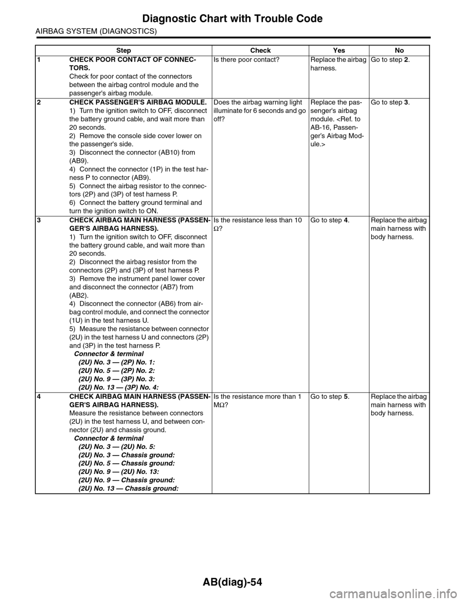
2CHECK PASSENGER'S AIRBAG MODULE.
1) Turn the ignition switch to OFF, disconnect
the battery ground cable, and wait more than
20 seconds.
2) Remove the console side cover lower on
the passenger's side.
3) Disconnect the connector (AB10) from
(AB9).
4) Connect the connector (1P) in the test har-
ness P to connector (AB9).
5) Connect the airbag resistor to the connec-
tors (2P) and (3P) of test harness P.
6) Connect the battery ground terminal and
turn the ignition switch to ON.
Does the airbag warning light
illuminate for 6 seconds and go
off?
Replace the pas-
senger's airbag
module.
ger’s Airbag Mod-
ule.>
Go to step 3.
3CHECK AIRBAG MAIN HARNESS (PASSEN-
GER'S AIRBAG HARNESS).
1) Turn the ignition switch to OFF, disconnect
the battery ground cable, and wait more than
20 seconds.
2) Disconnect the airbag resistor from the
connectors (2P) and (3P) of test harness P.
3) Remove the instrument panel lower cover
and disconnect the connector (AB7) from
(AB2).
4) Disconnect the connector (AB6) from air-
bag control module, and connect the connector
(1U) in the test harness U.
5) Measure the resistance between connector
(2U) in the test harness U and connectors (2P)
and (3P) in the test harness P.
Connector & terminal
(2U) No. 3 — (2P) No. 1:
(2U) No. 5 — (2P) No. 2:
(2U) No. 9 — (3P) No. 3:
(2U) No. 13 — (3P) No. 4:
Is the resistance less than 10
Ω?
Go to step 4.Replace the airbag
main harness with
body harness.
4CHECK AIRBAG MAIN HARNESS (PASSEN-
GER'S AIRBAG HARNESS).
Measure the resistance between connectors
(2U) in the test harness U, and between con-
nector (2U) and chassis ground.
Connector & terminal
(2U) No. 3 — (2U) No. 5:
(2U) No. 3 — Chassis ground:
(2U) No. 5 — Chassis ground:
(2U) No. 9 — (2U) No. 13:
(2U) No. 9 — Chassis ground:
(2U) No. 13 — Chassis ground:
Is the resistance more than 1
MΩ?
Go to step 5.Replace the airbag
main harness with
body harness.