Page 699 of 2453
WW-4
General Description
WIPER AND WASHER SYSTEMS
3. WASHER TANK
C: CAUTION
•Connect the connectors and hoses securely during reassembly.
•After reassembly, make sure functional parts operate smoothly.
•Be careful with the airbag system wire harness which passes near electrical parts and switches.
•All airbag system wiring harness and connectors are colored yellow. Do not use a tester equipment on
these circuits.
•Care must be taken when connecting the hoses to pipes so that there are no bends or blockage.
•If even a small amount of silicon oil or grease enters tank and washer fluid passages, an oil film will be
formed on the glass and will cause the wiper to chatter and judder. Make sure that no oil comes into contact
with the system.
(1) Washer nozzle (5) Front washer motorTightening torque: N·m (kgf-m, ft-lb)
(2) Washer hose (6) Rear washer motorT: 6.0 (0.61, 4.4)
(3) Washer tank (7) Grommet
(4) Washer tank cap (8) Washer motor cover
Page 2308 of 2453

WI-24
Ground Circuit
WIRING SYSTEM
WI-08032
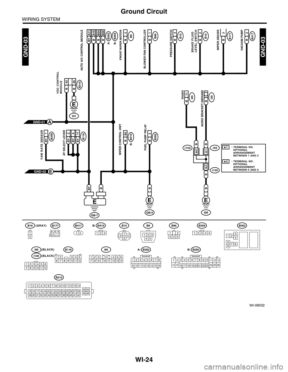
GND-03GND-03
B177B2
WIPER DEICER
B10B3
PRESSURE SWITCH
B8B2
FRONT WIPER MOTOR
BRAKE FLUIDLEVEL SWITCH
A:
B16B2B282
B:
B410
B:
B283B A16
AUTO A/C CONTROL MODULE
B86B1
BLOWER FAN CONTROLLER
B116BY 2BY 6BY 11
AT SELECT LEVER
B B2
WIPER CONTROL UNIT
3
B362B
FUEL PUMP RELAY
RADIOi85B 11i29B
AUDIO BRACKET GROUND
GND-02E
BB
GB-7
BBY
GRGB-5
(GRAY)B16
12
B10
2314
B8
13245
B362
12
78
3456
GND-01A
B177
B417B2
VACUUM PUMP
2
B359BY
1
YAW RATE SENSOR
BY A11B A16B B24B B26
B310
VDC CONTROLMODULEB 43B 46
GV
21
B283A:
345678910
16 17 18 19 20
121112132425262122231415
B282B:
B:
12345678
910 1112 1314 1516
B310
1234
1516171819202122232425262728293031323334353637383940414245464344568910 11 12 13 147
B417
1212345123
B359B410B86
i100
i100i99BB
B
1*
2*
2*
123456789101112
i99(BLACK)
i100(BLACK)
: TERMINAL NO. OPTIONAL ARRANGEMENT BETWEEN 1 AND 2
: TERMINAL NO. OPTIONAL ARRANGEMENT BETWEEN 5 AND 6
1*
2*
i85
2345817910111213614
B116
123467891011512
12345
Page 2436 of 2453

WI-152
Bulkhead Wiring Harness (In Engine Compartment)
WIRING SYSTEM
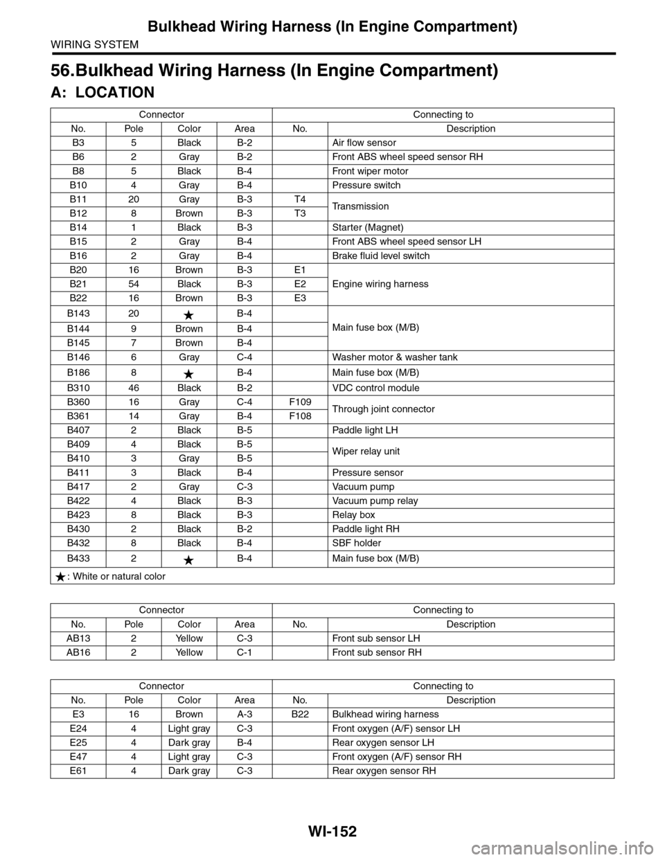
56.Bulkhead Wiring Harness (In Engine Compartment)
A: LOCATION
Connector Connecting to
No. Pole Color Area No. Description
B3 5 Black B-2 Air flow sensor
B6 2 Gray B-2 Front ABS wheel speed sensor RH
B8 5 Black B-4 Front wiper motor
B10 4 Gray B-4 Pressure switch
B11 20 Gray B-3 T4Tr a n s m i s s i o nB12 8 Brown B-3 T3
B14 1 Black B-3 Starter (Magnet)
B15 2 Gray B-4 Front ABS wheel speed sensor LH
B16 2 Gray B-4 Brake fluid level switch
B20 16 Brown B-3 E1
Engine wiring harnessB21 54 Black B-3 E2
B22 16 Brown B-3 E3
B143 20 B-4
Main fuse box (M/B)B144 9 Brown B-4
B145 7 Brown B-4
B146 6 Gray C-4 Washer motor & washer tank
B186 8 B-4 Main fuse box (M/B)
B310 46 Black B-2 VDC control module
B360 16 Gray C-4 F109Through joint connectorB361 14 Gray B-4 F108
B407 2 Black B-5 Paddle light LH
B409 4 Black B-5Wiper relay unitB410 3 Gray B-5
B411 3 Black B-4 Pressure sensor
B417 2 Gray C-3 Vacuum pump
B422 4 Black B-3 Vacuum pump relay
B423 8 Black B-3 Relay box
B430 2 Black B-2 Paddle light RH
B432 8 Black B-4 SBF holder
B433 2 B-4 Main fuse box (M/B)
: White or natural color
Connector Connecting to
No. Pole Color Area No. Description
AB13 2 Yellow C-3 Front sub sensor LH
AB16 2 Yellow C-1 Front sub sensor RH
Connector Connecting to
No. Pole Color Area No. Description
E3 16 Brown A-3 B22 Bulkhead wiring harness
E24 4 Light gray C-3 Front oxygen (A/F) sensor LH
E25 4 Dark gray B-4 Rear oxygen sensor LH
E47 4 Light gray C-3 Front oxygen (A/F) sensor RH
E61 4 Dark gray C-3 Rear oxygen sensor RH