2009 SUBARU TRIBECA fuel
[x] Cancel search: fuelPage 225 of 2453
EB-6
General Description
EXTERIOR BODY PANELS
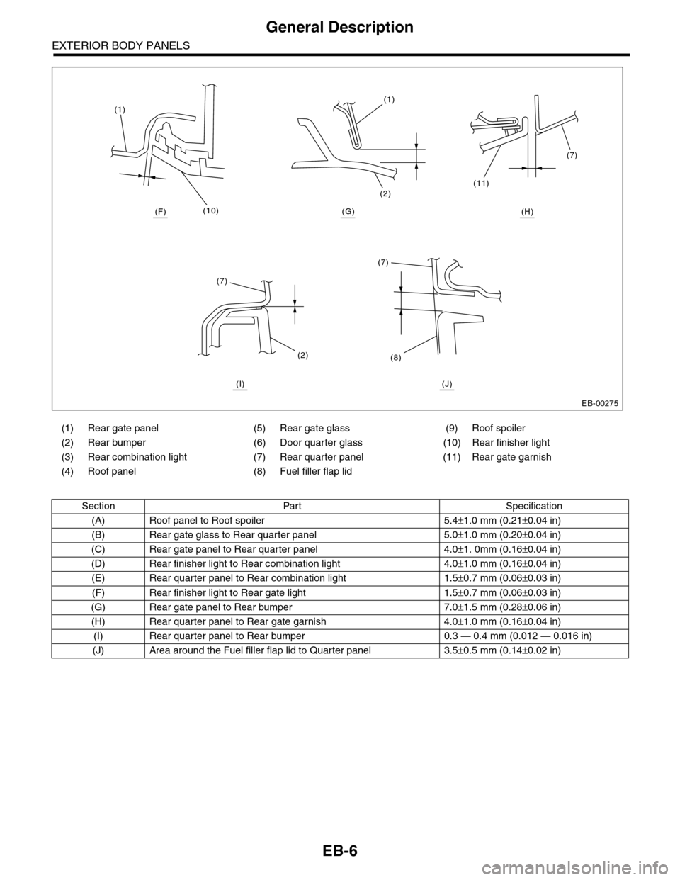
(1) Rear gate panel (5) Rear gate glass (9) Roof spoiler
(2) Rear bumper (6) Door quarter glass (10) Rear finisher light
(3) Rear combination light (7) Rear quarter panel (11) Rear gate garnish
(4) Roof panel (8) Fuel filler flap lid
Section Part Specification
(A) Roof panel to Roof spoiler 5.4±1.0 mm (0.21±0.04 in)
(B) Rear gate glass to Rear quarter panel 5.0±1.0 mm (0.20±0.04 in)
(C) Rear gate panel to Rear quarter panel 4.0±1. 0mm (0.16±0.04 in)
(D) Rear finisher light to Rear combination light 4.0±1.0 mm (0.16±0.04 in)
(E) Rear quarter panel to Rear combination light 1.5±0.7 mm (0.06±0.03 in)
(F) Rear finisher light to Rear gate light 1.5±0.7 mm (0.06±0.03 in)
(G) Rear gate panel to Rear bumper 7.0±1.5 mm (0.28±0.06 in)
(H) Rear quarter panel to Rear gate garnish 4.0±1.0 mm (0.16±0.04 in)
(I) Rear quarter panel to Rear bumper 0.3 — 0.4 mm (0.012 — 0.016 in)
(J) Area around the Fuel filler flap lid to Quarter panel 3.5±0.5 mm (0.14±0.02 in)
EB-00275
(10)
(1)(1)
(2)
(7)
(11)
(7)
(8)(2)
(7)
(H)(G)(F)
(I) (J)
Page 245 of 2453
EI-3
General Description
EXTERIOR/INTERIOR TRIM
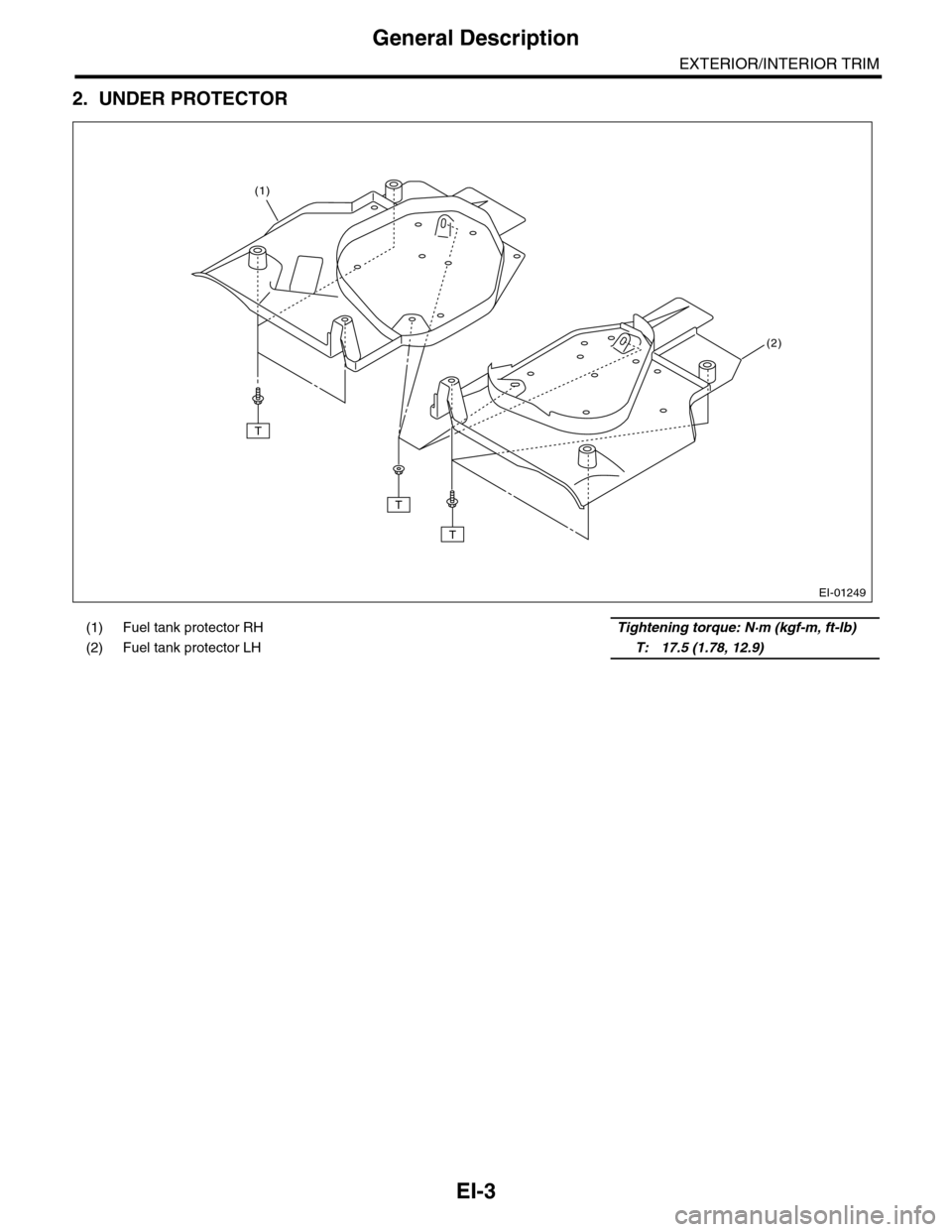
2. UNDER PROTECTOR
(1) Fuel tank protector RHTightening torque: N·m (kgf-m, ft-lb)
(2) Fuel tank protector LH T: 17.5 (1.78, 12.9)
EI-01249
T
T
T
(2)
(1)
Page 260 of 2453
EI-18
Fuel Tank Protector
EXTERIOR/INTERIOR TRIM
3. Fuel Tank Protector
A: REMOVAL
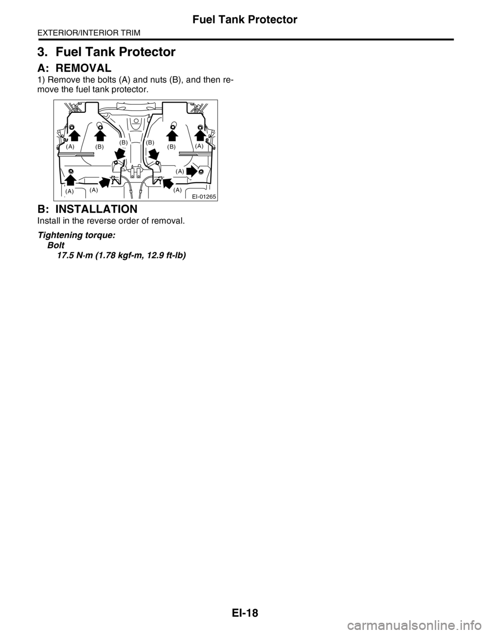
1) Remove the bolts (A) and nuts (B), and then re-
move the fuel tank protector.
B: INSTALLATION
Install in the reverse order of removal.
Tightening torque:
Bolt
17.5 N·m (1.78 kgf-m, 12.9 ft-lb)
EI-01265(A)
(A)(A)
(A)
(A)
(A)
(B)(B)(B)(B)
Page 295 of 2453
EI-53
Heat Shield Cover
EXTERIOR/INTERIOR TRIM
26.Heat Shield Cover
A: REMOVAL
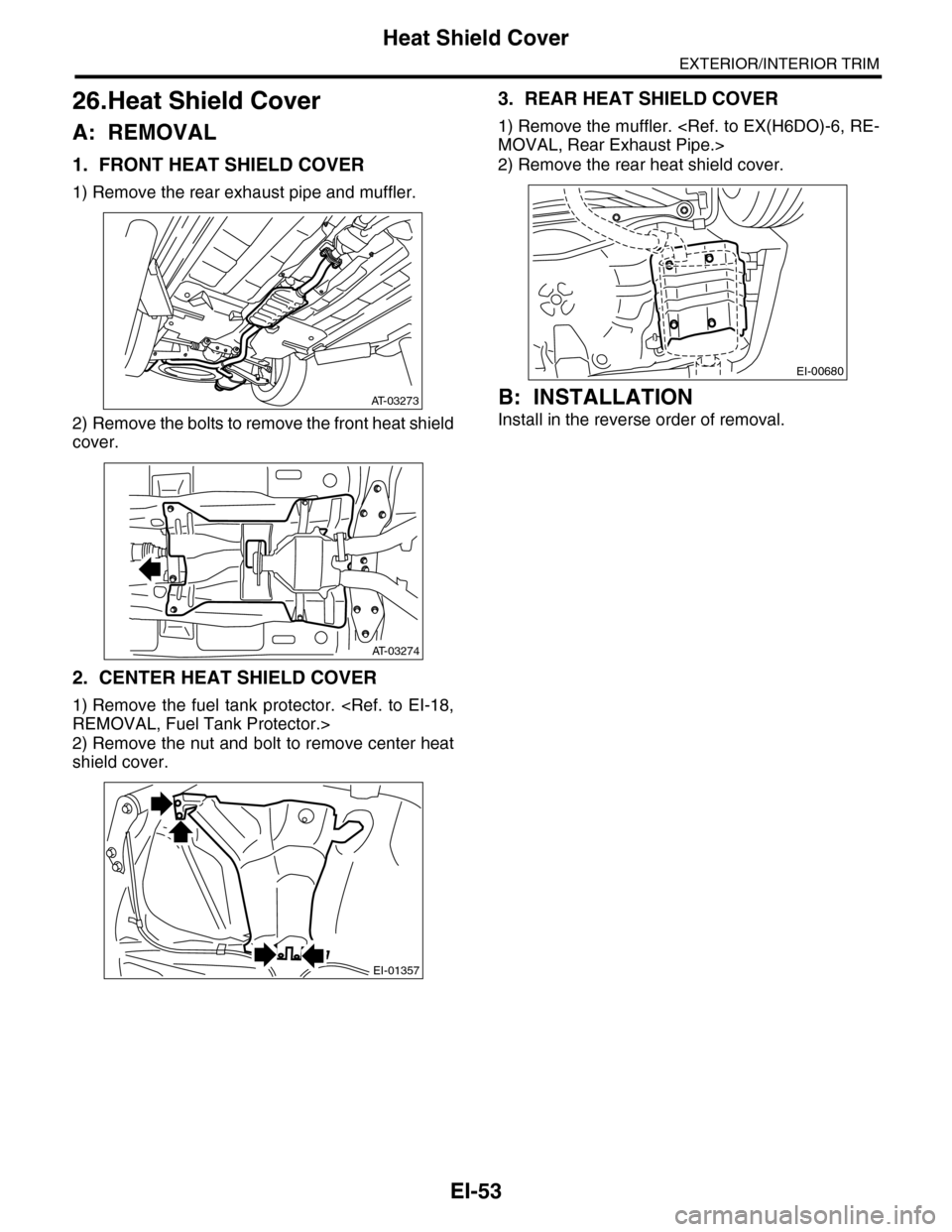
1. FRONT HEAT SHIELD COVER
1) Remove the rear exhaust pipe and muffler.
2) Remove the bolts to remove the front heat shield
cover.
2. CENTER HEAT SHIELD COVER
1) Remove the fuel tank protector.
2) Remove the nut and bolt to remove center heat
shield cover.
3. REAR HEAT SHIELD COVER
1) Remove the muffler.
2) Remove the rear heat shield cover.
B: INSTALLATION
Install in the reverse order of removal.
AT-03273
AT-03274
EI-01357
EI-00680
Page 441 of 2453
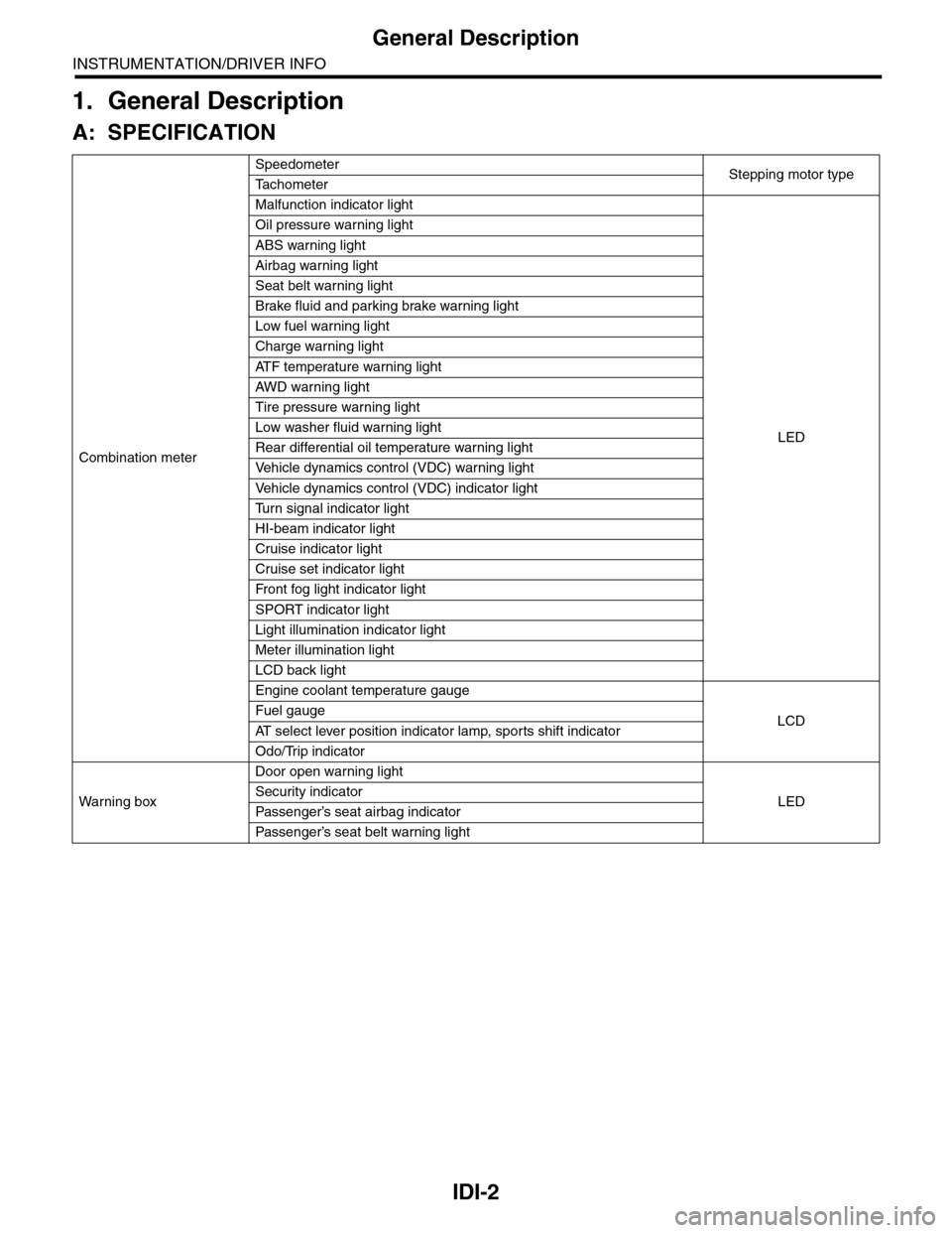
IDI-2
General Description
INSTRUMENTATION/DRIVER INFO
1. General Description
A: SPECIFICATION
Combination meter
SpeedometerStepping motor typeTa c h o m e t e r
Malfunction indicator light
LED
Oil pressure warning light
ABS warning light
Airbag warning light
Seat belt warning light
Brake fluid and parking brake warning light
Low fuel warning light
Charge warning light
AT F t e m p e r a t u r e w a r n i n g l i g h t
AW D war n in g l i gh t
Tire pressure warning light
Low washer fluid warning light
Rear differential oil temperature warning light
Ve h i c l e d y n a m i c s c o n t r o l ( V D C ) w a r n i n g l i g h t
Ve h i c l e d y n a m i c s c o n t r o l ( V D C ) i n d i c a t o r l i g h t
Tu r n s i g n a l i n d i c a t o r l i g h t
HI-beam indicator light
Cruise indicator light
Cruise set indicator light
Fr o nt fog li g ht i nd i ca to r li g ht
SPORT indicator light
Light illumination indicator light
Meter illumination light
LCD back light
Engine coolant temperature gauge
LCDFuel gauge
AT s e l e c t l e v e r p o s i t i o n i n d i c a t o r l a m p , s p o r t s s h i f t i n d i c a t o r
Odo/Trip indicator
Wa r ni n g b ox
Door open warning light
LEDSecurity indicator
Passenger’s seat airbag indicator
Passenger’s seat belt war ning light
Page 444 of 2453

IDI-5
Combination Meter System
INSTRUMENTATION/DRIVER INFO
2. LIST OF SELF-DIAGNOSIS MODE OPERATION
Speedometer,
tachometer, fuel
gauge, engine
coolant temper-
ature gauge
Microcomputer
running type
warning light,
indicator light
AT s e l e c t l e v e r
position indica-
tor light
Odo/Trip indica-
tor
SPORT shift
indicator
Illumination
(indicator nee-
dle, plate, ring,
LCD)
Buzzer (SPORT
shift buzzer)
Step 0. Processing to self-diagnosis function
Operating initial
operation
Initial illuminat-
ing
Normal Normal Initial illuminat-
ing
Initial illuminat-
ing
Not beep.
Step 1-1. Check each indication after initial operation
Repeat the
sweep opera-
tion (After hold-
ing on lowest
position for one
second, reaches
to highest posi-
tion within 5
seconds, and
after holding on
highest position
for one second,
reaches to low-
est position
within 5 sec-
onds).
Light ON With the high-
est brightness,
illuminate the
position sequen-
tially at a cycle
of 1. 5 seconds.
For the illumina-
tion order, refer
to the illumina-
tion order table.
Pe r for m t he s eg -
ment check. For
the illumination
order, refer to
the illumination
order table.
Pe rfo r m t h e se g -
ment check. For
the illumination
order, refer to
the illumination
order table.
Light at the
highest bright-
ness.
Not beep.
Step 1-2. Press the trip knob (trip knob input is not accepted till the meter indicator needle reaches the highest position): sweep
complete, AT select lever position indicator display is set
After complet-
ing sweep in
step 1-1, back to
lowest position.
Light ON Keep the posi-
tion indicated
when the trip
knob is pressed.
Underbar “ _ ” is
displayed.
“1” is displayed. Light at the
highest bright-
ness.
Not beep.
Step 2-1. Press the trip knob, and hold it: Check each meter
All meters are
moved simulta-
neously in every
0.5 sec. from
the lowest posi-
tion to highest
position.
Speedometer/
Ta c h o m e t e r :
Approx. 5
degrees at
ever y move-
ment.
Wa t er t e mp er a-
ture /Fuel
gauge: Moves 1
segment at a
time.
Light OFF Keep the posi-
tion indicated
that set in step
1-2.
Display the cur-
rent meter
directing angle
on odometer.
Ex.) Displays
135017 when
Speedometer/
Ta c h o m e t e r :
135 degrees,
Water tempera-
ture gauge/Fuel
gauge: 17 seg-
ments.
“2” is dis-
played.
Light at the
highest bright-
ness.
Not beep.
Step 2-2. Release the trip knob: Specifying the meter directing position
Stop at direct-
ing position
when the trip
knob is
released.
Light OFF Keep the posi-
tion indicated
that set in step
1-2.
Display the cur-
rent meter
directing angle
on odometer.
“2” is displayed. Light at the
highest bright-
ness.
Not beep.
Step 3-1. Press the trip knob, and hold it: Check illumination
Page 445 of 2453

IDI-6
Combination Meter System
INSTRUMENTATION/DRIVER INFO
•Illuminating order table
Keep the posi-
tion that speci-
fied at step 2-2.
Light OFF Varying from the
highest bright-
ness (ILL6) to
the lowest lumi-
nescence (ILL1)
ever y second.
After reaching at
ILL1, repeat it
from ILL6.
Illumination
brightness is
displayed in the
trip meter. (From
ILL6 to ILL1)
“3” is dis-
played.
Va r y i n g f r o m t h e
highest bright-
ness (ILL6) to
the lowest lumi-
nescence (ILL1)
every second.
After reaching at
ILL1, repeat it
from ILL6.
Not beep.
Step 3-2. Release the trip knob: Specifying the illumination brightness
Keep the posi-
tion that speci-
fied at step 2-2.
Light OFF Keep the bright-
ness at the time
when the trip
knob is
released.
Displays the
brightness at the
time when the
trip knob is
released in the
trip meter.
“3” is displayed. Keep the bright-
ness at the time
when the trip
knob is
released.
Not beep.
Step 4-1. Press the trip knob: Check the beeping of SPORT shift buzzer (For AT model)
All meter indica-
tor needle
returns to lowest
position.
Light OFF Light at the
highest bright-
ness. Keep the
position indi-
cated that set in
step 1-2.
Illumination
brightness is
displayed in the
trip meter.
“8” is dis-
played. Blinks
with buzzer.
Light at the
highest bright-
ness.
SPORT shift
buzzer beeps.
Step 4-2. Press the trip knob: Check the VDC indicator light (Model with VDC)
All meter indica-
tor needle
returns to lowest
position.
VDC warning
light and VDC
operation indica-
tor light blink.
Light at the
highest bright-
ness. Keep the
position indi-
cated that set in
step 1-2.
Illumination
brightness is
displayed in the
trip meter.
“4” is displayed. Light at the
highest bright-
ness.
Not beep.
Step5. Press the trip knob: Complete the self-diagnosis 1 cycle
All meter indicator needle returns to lowest position, and go back to step 1 after completion.
Illuminating
order1234567891011
Tr i p m e t e r A / B A B A B A B A B A B A B
Go back
to 1 and
repeat
Odo/trip meter
8888.8
88888
8
00000
00000
0
1111.1
11111
1
22222
22222
2
3333.3
33333
3
44444
44444
4
5555.5
55555
5
66666
66666
6
7777.7
77777
7
88888
88888
8
9999.9
99999
9
SPORT shift
indicator812345EPRND
Display time
(sec.)10.50.50.50.50.50.50.50.50.50.5
Speedometer,
tachometer, fuel
gauge, engine
coolant temper-
ature gauge
Microcomputer
running type
warning light,
indicator light
AT s e l e c t l e v e r
position indica-
tor light
Odo/Trip indica-
tor
SPORT shift
indicator
Illumination
(indicator nee-
dle, plate, ring,
LCD)
Buzzer (SPORT
shift buzzer)
Page 446 of 2453

IDI-7
Combination Meter System
INSTRUMENTATION/DRIVER INFO
3. SYMPTOM CHART
CAUTION:
When measuring the voltage and resistance of each control module or sensor, use a tapered pin with
a diameter of less than 0.64 mm (0.025 in) in order to avoid poor contact. Do not insert the pin more
than 2 mm (0.08 in).
4. CHECK POWER SUPPLY AND GROUND CIRCUIT
Symptom Repair order Note
Combination meter assembly does not
operate.
1. Power supply
2. Ground circuit
3. Combination meter
Combination Meter System.>
Speedometer does not operate. 1. VDCCM
2. Harness
3. Combination meter
tem.>
Ta c h o m e t e r d o e s n o t o p e r a t e . 1 . E C M
2. Harness
3. Combination meter
Combination Meter System.>
Fuel gauge does not operate. 1. Communication circuit
2. Fuel level sensor
3. Harness
4. Combination meter
Meter System.>
Engine coolant temperature gauge does
not operate.
1. Communication circuit
2. Engine coolant temperature sensor
3. Harness
4. Combination meter
INSPECTION, Combination Meter Sys-
tem.>
Error display is shown on the odo/trip
meter.
Communication circuit
nation Meter System.>
Step Check Yes No
1CHECK POWER SUPPLY FOR COMBINA-
TION METER.
1) Remove the combination meter.
2) Disconnect the combination meter harness
connector.
3) Turn the ignition switch to ON.
4) Measure the voltage between combination
meter connector and chassis ground.
Connector & terminal
(i10) No. 3, 4 (+) — Chassis ground (–):
Is the voltage more than 10 V? Go to step 2.Check the harness
for open or shor t
between the igni-
tion switch and
combination
meter.
2CHECK POWER SUPPLY FOR COMBINA-
TION METER.
Measure the voltage between combination
meter connector and chassis ground.
Connector & terminal
(i10) No. 1, 2 (+) — Chassis ground (–):
Is the voltage more than 10 V? Go to step 3.Check the harness
for open or shor t
between the fuse
and combination
meter.
3CHECK GROUND CIRCUIT OF COMBINA-
TION METER.
1) Turn the ignition switch to OFF.
2) Measure the resistance of harness
between combination meter connector and
chassis ground.
Connector & terminal
(i10) No. 15, 16 — Chassis ground:
Is the resistance less than 10
Ω?
Replace the meter
case assembly.
Repair the wiring
harness.