Page 674 of 2453

SL-45
Remote Openers
SECURITY AND LOCKS
16.Remote Openers
A: REMOVAL
1. FRONT HOOD OPENER
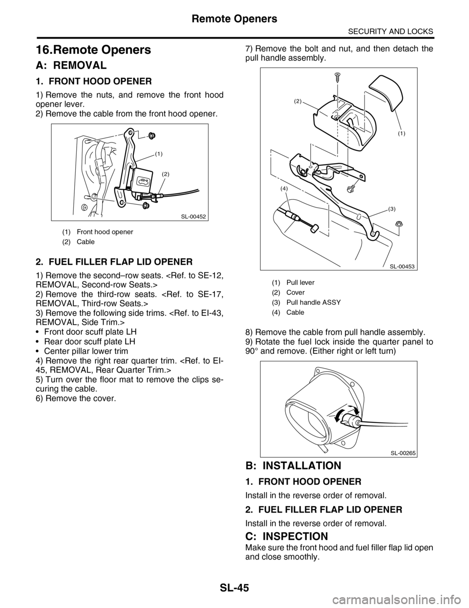
1) Remove the nuts, and remove the front hood
opener lever.
2) Remove the cable from the front hood opener.
2. FUEL FILLER FLAP LID OPENER
1) Remove the second–row seats.
REMOVAL, Second-row Seats.>
2) Remove the third-row seats.
REMOVAL, Third-row Seats.>
3) Remove the following side trims.
REMOVAL, Side Trim.>
•Front door scuff plate LH
•Rear door scuff plate LH
•Center pillar lower trim
4) Remove the right rear quarter trim.
45, REMOVAL, Rear Quarter Trim.>
5) Turn over the floor mat to remove the clips se-
curing the cable.
6) Remove the cover.
7) Remove the bolt and nut, and then detach the
pull handle assembly.
8) Remove the cable from pull handle assembly.
9) Rotate the fuel lock inside the quarter panel to
90° and remove. (Either right or left turn)
B: INSTALLATION
1. FRONT HOOD OPENER
Install in the reverse order of removal.
2. FUEL FILLER FLAP LID OPENER
Install in the reverse order of removal.
C: INSPECTION
Make sure the front hood and fuel filler flap lid open
and close smoothly.
(1) Front hood opener
(2) Cable
SL-00452
(2)
(1)
(1) Pull lever
(2) Cover
(3) Pull handle ASSY
(4) Cable
SL-00453
(3)
(2)
(4)
(1)
SL-00265
Page 855 of 2453
FS-7
Wheel Alignment
FRONT SUSPENSION
1. WHEEL ARCH HEIGHT
1) Park the vehicle on a level surface.
2) Empty the vehicle so that it is at “curb weight”. (Empty the luggage compartment, load the spare tire, jack
and service tools, and fill up the fuel tank.)
3) Set the steering wheel in a straight–ahead position, and stabilize the suspension by moving the vehicle in
a straight line for more than 5 m (16 ft).
4) Suspend a thread from the wheel arch (point “A” in the figure below) and affix at a position directly above
the center of wheel.
5) Measure the distance between the point “A” and the center of wheel.
(1) Wheel arch height (4) Front wheel arch height (7) Point of measurement
(2) Front fender (5) Rear wheel arch height (8) Tip end of spindle
(3) Rear quarter (6) Flange bend line
Wheel arch height specification mm (in) (Tolerance: +12 mm –24 mm ( +0.47 in –0.94 in))
Front 442 (17.4)
Rear 439 (17.3)
A
A
A
(4)
(1)
(2)
(3)
(1)
(5)(1)
(7)
(6)
(8)
FS-00210
Page 1086 of 2453

VDC-5
General Description
VEHICLE DYNAMICS CONTROL (VDC)
5. RELAY BOX
C: CAUTION
Please clearly understand and adhere to the follow-
ing general precautions. They must be strictly fol-
lowed to avoid any injury to the person doing the
work or people in the area.
1. OPERATION
•Wear work clothing, including a cap, protective
goggles and protective shoes during operation.
•Remove contamination including dirt and corro-
sion before removal, installation or disassembly.
•Keep the disassembled parts in order and pro-
tect them from dust and dirt.
•Before disconnecting connectors of sensors or
units, be sure to disconnect the ground cable from
the battery.
•Before removal, installation or disassembly, be
sure to clarify the failure. Avoid unnecessary re-
moval, installation, disassembly and replacement.
•Be careful not to burn yourself, because each
part on the vehicle is hot after running.
•Be sure to tighten fasteners including bolts and
nuts to the specified torque.
•Place shop jacks or rigid racks at the specified
points.
2. OIL
When handling oil, follow the rules below to prevent
unexpected accidents.
•Prepare container and waste cloths when per-
forming work which oil could possibly spill. If oil
spills, wipe it off immediately to prevent from pene-
trating into floor or flowing outside, for environmen-
tal protection.
•Follow all government and local regulations con-
cerning waste disposal.
3. BRAKE FLUID
If brake fluid gets in your eyes or on your skin, do
the following:
•Wash eyes and seek immediate medical atten-
tion.
•Wash your skin with soap and then rinse thor-
oughly with water.
Follow all government and local regulations con-
cerning waste disposal.
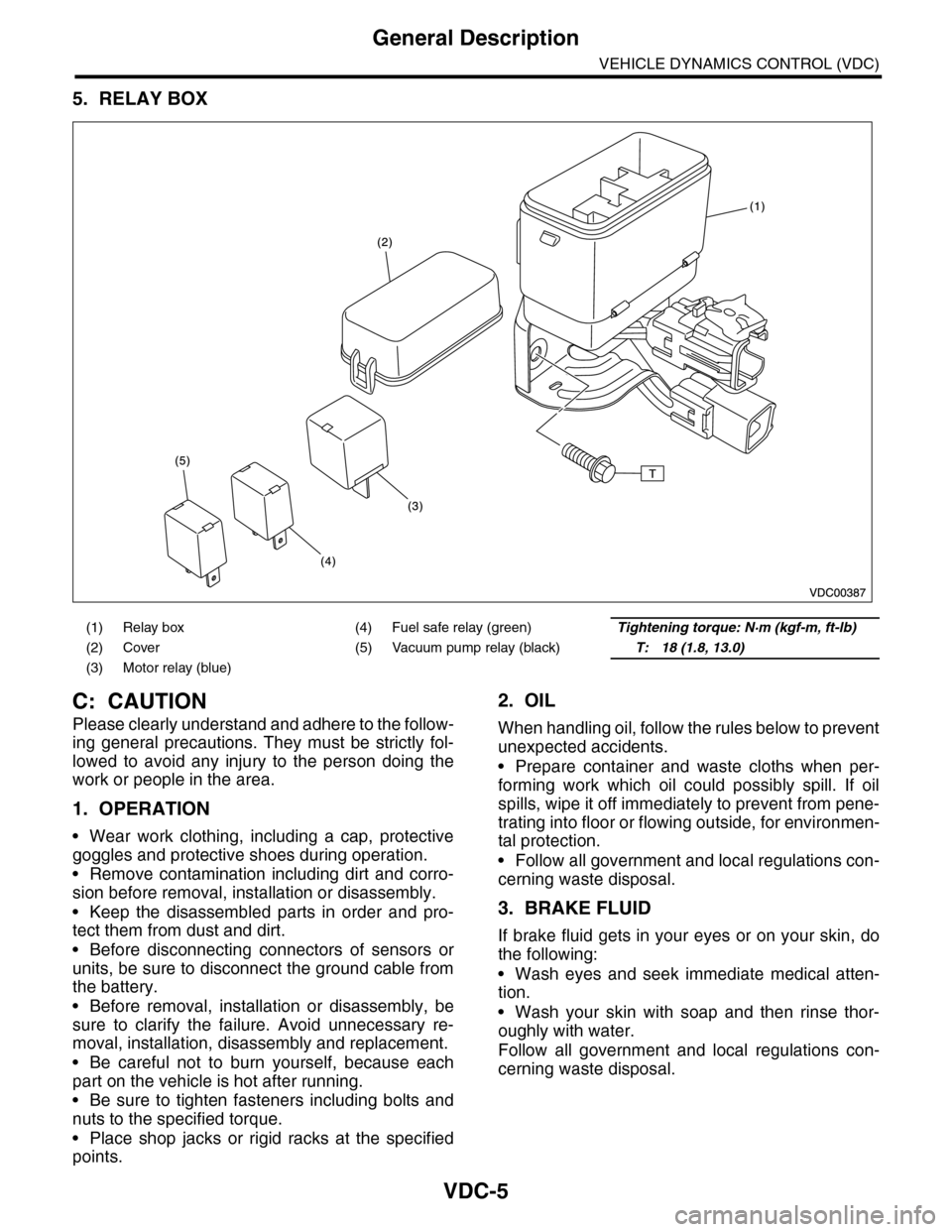
(1) Relay box (4) Fuel safe relay (green)Tightening torque: N·m (kgf-m, ft-lb)
(2) Cover (5) Vacuum pump relay (black)T: 18 (1.8, 13.0)
(3) Motor relay (blue)
Page 1149 of 2453

CO(H6DO)-30
Engine Cooling System Trouble in General
COOLING
12.Engine Cooling System Trouble in General
A: INSPECTION
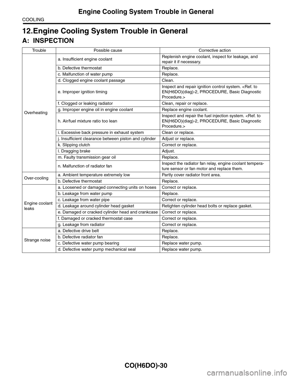
Tr o u b l e P o s s i b l e c a u s e C o r r e c t i v e a c t i o n
Overheating
a. Insufficient engine coolantReplenish engine coolant, inspect for leakage, and
repair it if necessary.
b. De fe c ti ve t he r mo st a t Rep la c e.
c. Malfunction of water pump Replace.
d. Clogged engine coolant passage Clean.
e. Improper ignition timing
Inspect and repair ignition control system.
EN(H6DO)(diag)-2, PROCEDURE, Basic Diagnostic
Procedure.>
f. Clogged or leaking radiator Clean, repair or replace.
g. Improper engine oil in engine coolant Replace engine coolant.
h. Air/fuel mixture ratio too lean
Inspect and repair the fuel injection system.
EN(H6DO)(diag)-2, PROCEDURE, Basic Diagnostic
Procedure.>
i. Excessive back pressure in exhaust system Clean or replace.
j. Insufficient clearance between piston and cylinder Adjust or replace.
k. Slipping clutch Correct or replace.
l. Dragging brake Adjust.
m. Faulty transmission gear oil Replace.
n. Malfunction of radiator fanInspect the radiator fan relay, engine coolant tempera-
ture sensor or fan motor and replace them.
Over-coolinga. Ambient temperature extremely low Partly cover radiator front area.
b. De fe c ti ve t he r mo st a t Rep la c e.
Engine coolant
leaks
a. Loosened or damaged connecting units on hoses Correct or replace.
b. L ea k ag e f r o m wat e r pu mp Rep la c e.
c. Leakage from water pipe Correct or replace.
d. Leakage around cylinder head gasket Retighten cylinder head bolts or replace gasket.
e. Damaged or cracked cylinder head and crankcase Correct or replace.
f. Damaged or cracked ther mostat case Correct or replace.
g. Leakage from radiator Correct or replace.
Strange noise
a. Defective drive belt Replace.
b. De fe c ti ve ra di a t or fan Rep la c e.
c. Defective water pump bearing Replace water pump.
d. Defective water pump mechanical seal Replace water pump.
Page 1154 of 2453
EC(H6DO)-6
Purge Control Solenoid Valve
EMISSION CONTROL (AUX. EMISSION CONTROL DEVICES)
5. Purge Control Solenoid Valve
A: REMOVAL
1) Remove the collector cover.
2) Disconnect the ground cable from battery.
3) Remove the air intake chamber.
ber.>
4) Disconnect the connector and hoses of purge
control solenoid valve, and then remove the purge
control solenoid valve.
B: INSTALLATION
Install in the reverse order of removal.
Tightening torque:
19 N·m (1.9 kgf-m, 14.0 ft-lb)
NOTE:
Connect the evaporation hose as shown in the fig-
ure.
C: INSPECTION
Make sure the hoses are not cracked or loose.
(A) To fuel pipe (evaporation line)
(B) To intake manifold
EC-02019
EC-02019
EC-02020
(B)
(A)
Page 1155 of 2453
EC(H6DO)-7
Fuel Level Sensor
EMISSION CONTROL (AUX. EMISSION CONTROL DEVICES)
6. Fuel Level Sensor
A: REMOVAL
For removal procedure, refer to “FU(H6DO)” sec-
tion.
el Sensor.>
B: INSTALLATION
For installation procedure, refer to “FU(H6DO)”
section.
Fuel Level Sensor.>
Page 1156 of 2453
EC(H6DO)-8
Fuel Temperature Sensor
EMISSION CONTROL (AUX. EMISSION CONTROL DEVICES)
7. Fuel Temperature Sensor
A: REMOVAL
The fuel temperature sensor and fuel level sensor
are integrated into one unit; therefore, refer to “Fuel
Level Sensor” for removal procedure.
FU(H6DO)-45, REMOVAL, Fuel Level Sensor.>
B: INSTALLATION
The fuel temperature sensor and fuel level sensor
are integrated into one unit; therefore, refer to “Fuel
Level Sensor” for installation procedure.
FU(H6DO)-45, INSTALLATION, Fuel Level Sen-
sor.>
Page 1157 of 2453
EC(H6DO)-9
Fuel Sub Level Sensor
EMISSION CONTROL (AUX. EMISSION CONTROL DEVICES)
8. Fuel Sub Level Sensor
A: REMOVAL
For removal procedure, refer to “FU(H6DO)” sec-
tion.
Level Sensor.>
B: INSTALLATION
For installation procedure, refer to “FU(H6DO)”
section.
Fuel Sub Level Sensor.>