2009 SUBARU TRIBECA remote control
[x] Cancel search: remote controlPage 306 of 2453

GW-11
Remote Control Mirror System
GLASS/WINDOWS/MIRRORS
6. Remote Control Mirror System
A: WIRING DIAGRAM
B: INSPECTION
Symptom Repair order
All function does not operate.
1. Fuse (F/B No. 6)
2. Mirror switch
3. Wiring harness
One side of the mirror motor does not operate.
1. Mirror switch
2. Mirror motor
3. Wiring harness
Mirror heater does not operate.
1. Mirror switch
2. Mirror heater
3. Wiring harness
Page 310 of 2453

GW-15
Remote Control Mirror Switch
GLASS/WINDOWS/MIRRORS
10.Remote Control Mirror
Switch
A: REMOVAL
1) Remove the instrument panel lower cover.
er.>
2) Disconnect the connector.
3) Remove the remote control mirror switch from
instrument panel lower cover.
B: INSTALLATION
Install in the reverse order of removal.
C: INSPECTION
1. REMOTE CONTROL MIRROR SWITCH
Move the remote control mirror switch to each po-
sition and check continuity between terminals.
•Change over switch R
•Change over switch L
Replace the remote control mirror switch if defec-
tive.
GW-00486
LR
OFFOFF
Switch posi-
tionTe r m i n a l N o . S t a n d a r d
OFF — 1 MΩ or more
UP10 and 12
15 and 14Less than 1 Ω
DOWN10 and 15
12 and 14Less than 1 Ω
LEFT10 and 11
15 and 14Less than 1 Ω
RIGHT10 and 15
11 and 14Less than 1 Ω
Switch posi-
tionTe r m i n a l N o . S t a n d a r d
OFF — 1 MΩ or more
UP10 and 8
15 and 14Less than 1 Ω
DOWN10 and 15
8 and 14Less than 1 Ω
LEFT10 and 9
15 and 14Less than 1 Ω
RIGHT10 and 15
9 and 14Less than 1 Ω
GW-00283
914
7654321
8131211101615
Page 476 of 2453

LAN(diag)-20
Subaru Select Monitor
LAN SYSTEM (DIAGNOSTICS)
CAUTION:
•It is possible to control the original functions of vehicle when registrations of body integrated
unit and function setting are corresponded to vehicle equipment.
•When body integrated unit is a new one or “Factory” mode, key illumination blinks to show
equipment settings have not been completed.
•Be sure not to change Factory initial setting except installation of new body integrated unit.
NOTE:
“Factory” mode:
•Body integrated unit has not been set yet. It can be recognized by key illumination blinking with ignition
switch turned to ON.
•All body integrated units as part for repair are set to “Factory” mode. When replacing a body integrated
unit, be sure to perform the registration operation.
“Market” mode:
Each settings have been set. It can be recognized by key illumination coming on in concocting with room light
and going off with ignition switch turned to ON.
7) Perform the Factory setting. On the «ECM customizing” display screen of Subaru Select Monitor, select
the {Factory initial setting} and press the [YES] key.
8) Change the mode from Factory to Market.
9) Register the immobilizer key.
10) Perform the registration according to the procedures of the “IMMOBILIZER REGISTRATION OPERA-
TION MANUAL”.
11) When key registration is completed, “Do you want to register remote engine start?” is displayed. Select
NO.
12) Perform the function setting (ECM customizing).
NOTE:
For details concerning operation procedure, refer to the “SUBARU SELECT MONITOR OPERATION MAN-
UAL”.
DataInitial set-
tingRegistration Remarks
A/C ECM setting OFF
ONIllumination control does not operate if A/C ECM setting is
set to “OFF” in case of model with auto A/C.
OFF
If A/C ECM setting is set to “ON” in case of model without
auto A/C, illumination change to night illumination and it is
difficult to be recognized.
P/W ECM setting OFFONSet to “OFF”.OFF
Center display failure OFFONIf center display failure is set to “OFF”, diagnosis for MFD
and navigation display cannot be performed.OFF
Wiper deicer setting OFF
ON ON signal does not output with operation of wiper deicer
switch if wiper deicer is set to “OFF” in models with a wiper
deicer.OFF
Rear fog light setting OFFONSet to “OFF”.OFF
Fac t or y in i ti a l s et t i ng ( Res et
of body integrated unit)Fac to r y
Fa ct or y ( Re se t )If Factory initial setting is set to “Factory”, registrations of
items above is changed to “OFF”. After setting, be sure to
set to “Market”.Market (Settle-
ment)
Page 653 of 2453

SL-24
Keyless Entry System
SECURITY AND LOCKS
14.CHECK KEYLESS BUZZER
Step Check Yes No
1CHECK KEYLESS BUZZER OPERATION.
Check that the keyless buzzer sounds when
LOCK or OPEN button of keyless remote con-
trol key is pressed.
Does the keyless buzzer
sound?
Keyless buzzer is
normal.
Go to step 2.
2CHECK KEYLESS BUZZER ON/OFF
SWITCH.
NOTE:If operations 1-5 are performed with the keyless
buzzer OFF, the keyless buzzer will turn ON.
1) Close the driver’s side door and remove the
key from the ignition key cylinder.
2) Push the door lock switch to the UNLOCK
side, and insert the key into the ignition key cyl-
inder.
3) From 2, pull out ⇔ inser t the key from the
ignition key cylinder 5 times.
4) From 3, open → close the dr iver’s side door
within 10 seconds.
5) The keyless buzzer sound ON/OFF will
switch, and the hazard lamp will blink 3 times.
If the driver's side door is not opened → closed
within 10 seconds in step 4, the hazard lamp
will blink once and the setting will not be
changed.)
6) Check that the keyless buzzer sounds
when LOCK or OPEN button of keyless remote
control key is pressed.
Does the keyless buzzer
sound?
Keyless buzzer is
normal.
Go to step 3.
3CHECK FOR POWER SUPPLY OF KEYLESS
BUZZER.
1) Turn the ignition switch to OFF.
2) Disconnect the keyless buzzer harness
connector.
3) Press the LOCK/UNLOCK button of the
keyless transmitter.
4) Measure the voltage between harness con-
nector terminal and chassis ground.
Connector & terminal
(F102) No. 1 (+) — Chassis ground (– ):
Is the voltage more than 10 V? Go to step 4.Check the harness
for open circuits
and shorts
between the key-
less buzzer and
fuse.
4CHECK FOR GROUND CIRCUIT OF KEY-
LESS BUZZER.
1) Disconnect the harness connector of body
integrated unit.
2) Measure the resistance between harness
connector terminals.
Connector & terminal
(i84) No. 6 — (F102) No. 1:
Is the resistance less than 10
Ω?
Go to step 5.Repair the har-
ness.
5CHECK KEYLESS BUZZER.
1) Remove the keyless buzzer.
2) Install the keyless buzzer to another vehicle
which operates keyless buzzer normally, check
the buzzer sounds.
Does the keyless buzzer
sound?
Check the body
integrated unit or
door lock switch.
Diagnostic Proce-
dure.>
dow Control
Switch.>
Replace the key-
less buzzer.
Page 2304 of 2453

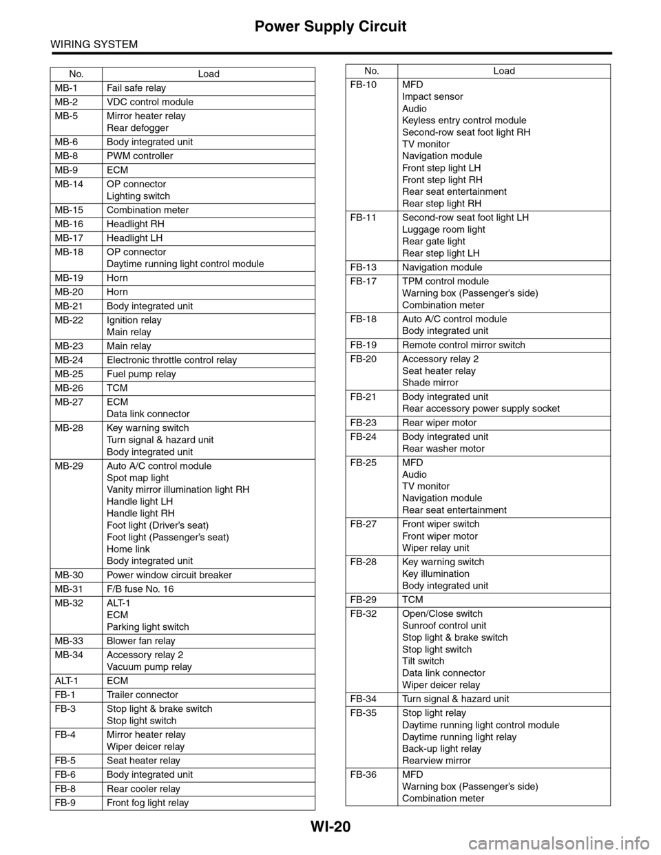
WI-20
Power Supply Circuit
WIRING SYSTEM
No. Load
MB-1 Fail safe relay
MB-2 VDC control module
MB-5 Mirror heater relay
Rear defogger
MB-6 Body integrated unit
MB-8 PWM controller
MB-9 ECM
MB-14 OP connector
Lighting switch
MB-15 Combination meter
MB-16 Headlight RH
MB-17 Headlight LH
MB-18 OP connector
Daytime running light control module
MB-19 Horn
MB-20 Horn
MB-21 Body integrated unit
MB-22 Ignition relay
Main relay
MB-23 Main relay
MB-24 Electronic throttle control relay
MB-25 Fuel pump relay
MB-26 TCM
MB-27 ECM
Data link connector
MB-28 Key warning switch
Tu r n s i g n a l & h a z a r d u n i t
Body integrated unit
MB-29 Auto A/C control module
Spot map light
Va n i t y m i r r o r i l l u m i n a t i o n l i g h t R H
Handle light LH
Handle light RH
Foot light (Driver’s seat)
Foot light (Passenger’s seat)
Home link
Body integrated unit
MB-30 Power window circuit breaker
MB-31 F/B fuse No. 16
MB-32 ALT-1
ECM
Par king light switch
MB-33 Blower fan relay
MB-34 Accessory relay 2
Va c u u m p u m p r e l ay
ALT-1 ECM
FB-1 Trailer connector
FB-3 Stop light & brake switch
Stop light switch
FB-4 Mirror heater relay
Wiper deicer relay
FB-5 Seat heater relay
FB-6 Body integrated unit
FB-8 Rear cooler relay
FB-9 Front fog light relay
FB-10 MFD
Impact sensor
Audio
Keyless entr y control module
Second-row seat foot light RH
TV monitor
Navigation module
Fr o n t s te p li gh t LH
Fr o n t s te p li gh t RH
Rear seat entertainment
Rear step light RH
FB-11 Second-row seat foot light LH
Luggage room light
Rear gate light
Rear step light LH
FB-13 Navigation module
FB-17 TPM control module
War ning box (Passenger’s side)
Combination meter
FB-18 Auto A/C control module
Body integrated unit
FB-19 Remote control mirror switch
FB-20 Accessory relay 2
Seat heater relay
Shade mirror
FB-21 Body integrated unit
Rear accessory power supply socket
FB-23 Rear wiper motor
FB-24 Body integrated unit
Rear washer motor
FB-25 MFD
Audio
TV monitor
Navigation module
Rear seat entertainment
FB-27 Front wiper switch
Fr o n t wi p er mo t or
Wiper relay unit
FB-28 Key warning switch
Key illumination
Body integrated unit
FB-29 TCM
FB-32 Open/Close switch
Sunroof control unit
Stop light & brake switch
Stop light switch
Tilt switch
Data link connector
Wiper deicer relay
FB-34 Turn signal & hazard unit
FB-35 Stop light relay
Daytime running light control module
Daytime running light relay
Back-up light relay
Rearview mirror
FB-36 MFD
War ning box (Passenger’s side)
Combination meter
No. Load
Page 2309 of 2453

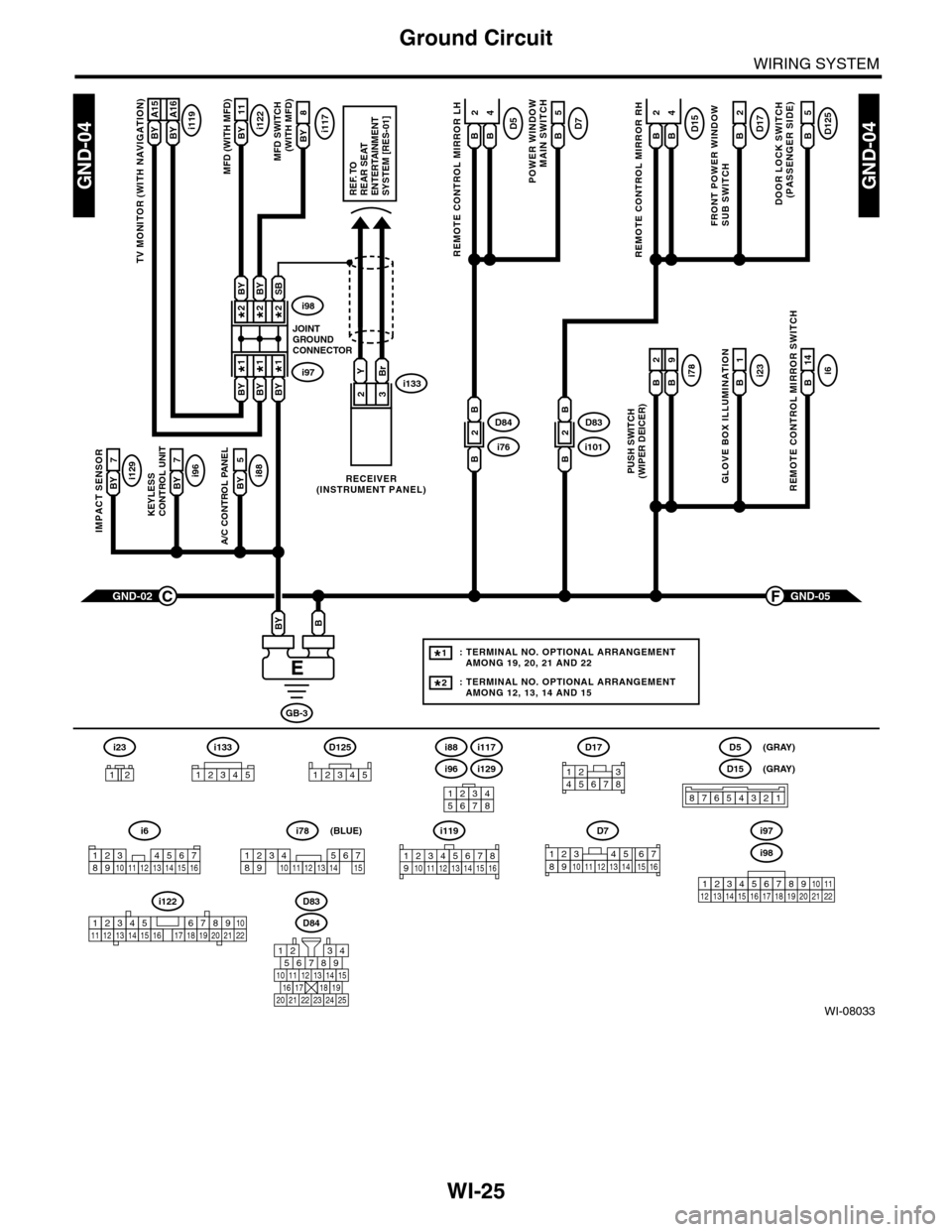
WI-25
Ground Circuit
WIRING SYSTEM
WI-08033
GND-04GND-04
i117BYi122BY 11
8
A/C CONTROL PANEL
i88BY 5
23
GND-05F
KEYLESS CONTROL UNIT
i96BY 7
IMPACT SENSOR
i129BY 7
TV MONITOR (WITH NAVIGATION)
i119BY A15BY A16
GND-02C
GB-3
BBY
D83
MFD (WITH MFD)MFD SWITCH (WITH MFD)
i96
12345678
i6
42
14
REMOTE CONTROL MIRROR SWITCH
i97i133
i98
JOINTGROUNDCONNECTOR
RECEIVER(INSTRUMENT PANEL)
2*2*
1*1*
2*
1*
BYBi231
GLOVE BOX ILLUMINATION
Bi789
PUSH SWITCH(WIPER DEICER)
B
2
BBYBY
SBBYBY
YBr
REF. TOREAR SEATENTERTAINMENT SYSTEM [RES-01]
: TERMINAL NO. OPTIONAL ARRANGEMENT AMONG 19, 20, 21 AND 22
: TERMINAL NO. OPTIONAL ARRANGEMENT AMONG 12, 13, 14 AND 15
1*
2*
D125
5
DOOR LOCK SWITCH(PASSENGER SIDE)
BD17
2
FRONT POWER WINDOW SUB SWITCH
POWER WINDOW
MAIN SWITCH
BD75
BD15
REMOTE CONTROL MIRROR RH
BB
42D5
REMOTE CONTROL MIRROR LH
BB
i1012D83
B
B
i762D84
B
B
D84
i88
i129
i117
567821943
10
2422 23 25
1112131415161718192021
i98
i97
12345678910111213141516171819202122
D7
12345689101112131514716
D17
12345678
D5
D15
87654321
(GRAY)
(GRAY)
i6
12345678910111213141516
i119
123 8910412 13 14 15 1656711
i133
12345
12345678910111213141516171819202122
i122
i78
123456789101112131415
(BLUE)
i23
12
D125
12345
Page 2378 of 2453

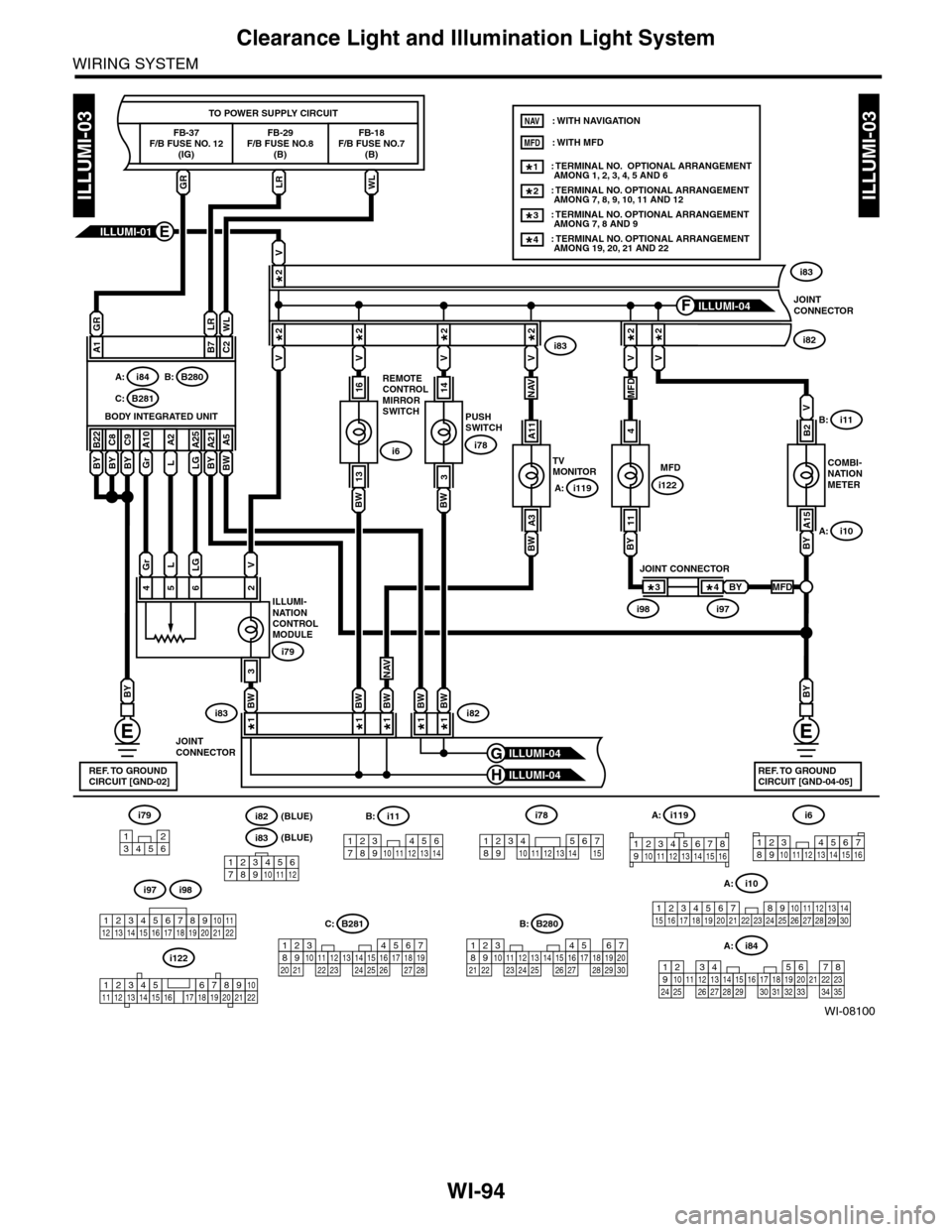
WI-94
Clearance Light and Illumination Light System
WIRING SYSTEM
WI-08100
ILLUMI-03ILLUMI-03
LGLGr
ILLUMI-NATIONCONTROLMODULE
i79
i83i82
4562
V
TO POWER SUPPLY CIRCUIT
FB-37F/B FUSE NO. 12(IG)
FB-18F/B FUSE NO.7(B)
FB-29F/B FUSE NO.8(B)
BYBW
3
A1C2B7
BYBW
B22
BY
C8A5
BY
A21
LG
A25
L
A2
Gr
A10
BODY INTEGRATED UNIT
B280B:i84A:
B281C:
V
VVV
JOINTCONNECTOR
i83
i82i83
B8JOINTCONNECTOR
BY
C9
V
PUSHSWITCH
i78
14
BW
3COMBI-NATIONMETER
i10A:
i11B:B2
V
BY
A15
MFD
i122
4
BY
11
BW
REMOTECONTROLMIRRORSWITCH
i6
16
BW
13
ILLUMI-01E
ILLUMI-04H
ILLUMI-04GREF. TO GROUNDCIRCUIT [GND-02]
BY
REF. TO GROUNDCIRCUIT [GND-04-05]
GRWLLR
GRLRWL
ILLUMI-04F
V
1234567891011121415161718192021222324252627282930313233343513
5467821931022 23111213141524 25 26 2716171828 29192021 30
567821943102422 23 25111213141526 27 281617181920 21
i78
131415123456789101112123456789101112
i79
123456
B281C:B280B:
i84A:
TVMONITOR
A11
BW
A3
V
BWBW1*1*1*
2*
2*2*2*2*2*2*
BW1*1*
A: i119
i119A:
123 8910412 13 14 15 1656711
12345678910111213141516171819202122
i122
BY
JOINT CONNECTOR
i98i97
4*3*MFD
NAV
NAVMFD
: TERMINAL NO. OPTIONAL ARRANGEMENT AMONG 1, 2, 3, 4, 5 AND 6: TERMINAL NO. OPTIONAL ARRANGEMENT AMONG 7, 8, 9, 10, 11 AND 12
1*
2*
: TERMINAL NO. OPTIONAL ARRANGEMENT AMONG 7, 8 AND 93*
: TERMINAL NO. OPTIONAL ARRANGEMENT AMONG 19, 20, 21 AND 224*
NAV
MFD: WITH MFD
: WITH NAVIGATION
i82(BLUE)
i83(BLUE)
i11
123 45678910 11 12 13 14
B:
i10
19 20 2115 16 17 182223242526272829301234568910 11 12 13 147
A:i98i97
12345678910111213141516171819202122
i6
12345678910111213141516
Page 2380 of 2453

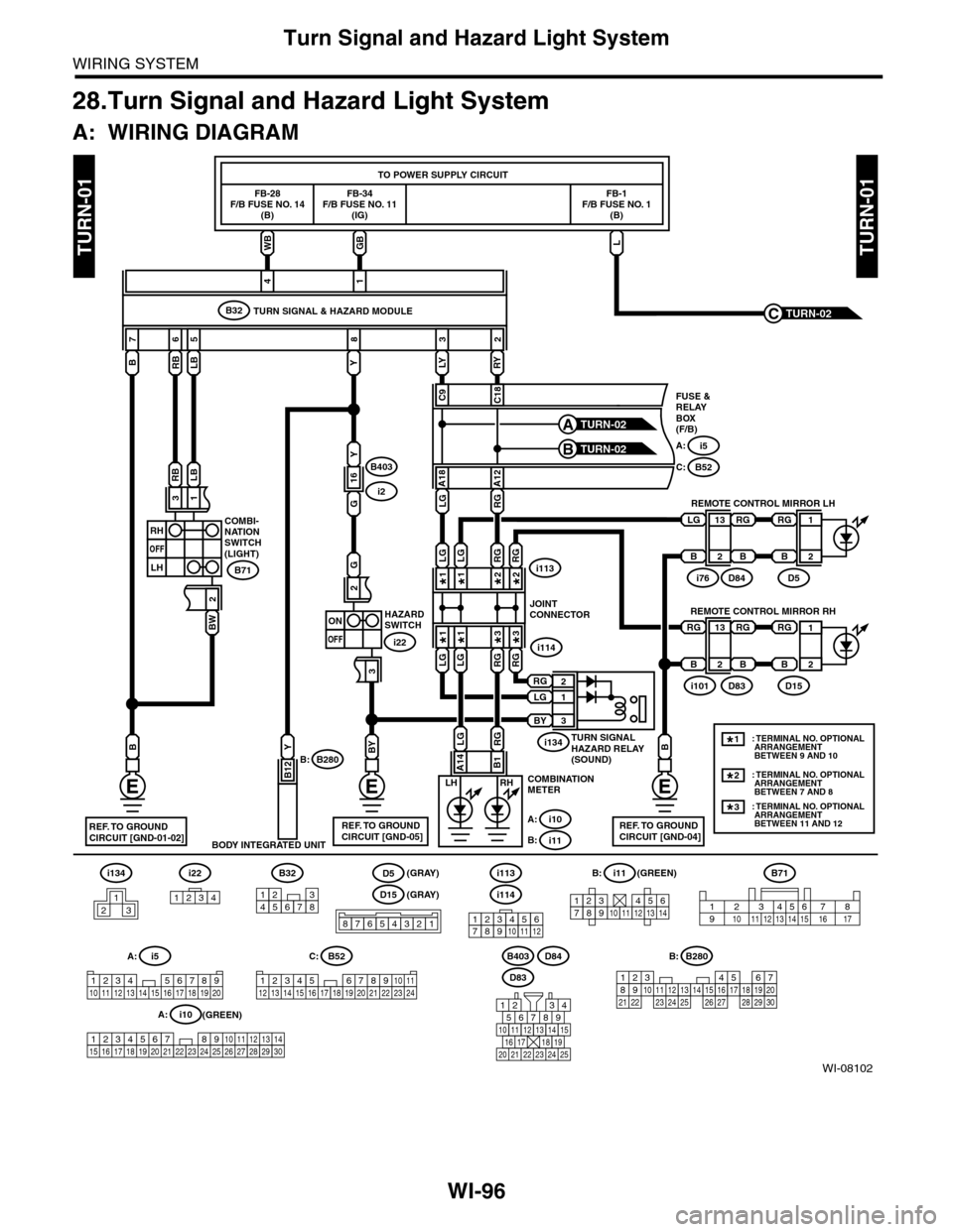
WI-96
Turn Signal and Hazard Light System
WIRING SYSTEM
28.Turn Signal and Hazard Light System
A: WIRING DIAGRAM
WI-08102
TURN-01TURN-01
i22i134
1234
B32
12345678123456789101112
i114
i113
1234567891011121314
i11B:B71
B403i5
1234 5678910 11 12 13 14 15 16 17 18 19 20
A: B52
3412 8910 1112 13 14 15 16 17 18 19 20 21 22 23 24567
C:
B
2
13
RY
C18
LY
C9
G
3
2
WBGB
FB-28F/B FUSE NO. 14(B)
FB-34F/B FUSE NO. 11(IG)
TO POWER SUPPLY CIRCUIT
B
7
RB
6
LB
53
Y
82
14
RHLH
i2
B403
Y
B12
BODY INTEGRATED UNIT
COMBI-NATIONSWITCH(LIGHT)
B280B:
RBLB
BW
31
RH
OFF
LH
2
B71
HAZARDSWITCH
i22
COMBINATIONMETER
i10A:
i11B:
i76D84
i5A:
C:B52
FUSE &RELAYBOX(F/B)
REMOTE CONTROL MIRROR LH
ON
OFF
TURN-02A
TURN-02B
TURN SIGNAL & HAZARD MODULEB32
LG
B2
1
D5
B
RG
D83
D84
567821943
10
2422 23 25
11121314151617181920 21
2
13
i101D83
RG
B
RG
B
RG
B
D15
B
RG
5467821931022 23111213141524 25 26 2716171828 29192021 30
B280B:
REF. TO GROUNDCIRCUIT [GND-01-02]REF. TO GROUNDCIRCUIT [GND-05]
23456718910 11 12 13 14 15 16 17
REMOTE CONTROL MIRROR RH
2
1
FB-1F/B FUSE NO. 1(B)
L
TURN-02C
16
G
Y
BY
REF. TO GROUNDCIRCUIT [GND-04]
B
RG
JOINTCONNECTOR
TURN SIGNALHAZARD RELAY(SOUND)
i114
i134
i1132*
3*
RG2*
RG
3*
RG
1*
LG
LG1*
1*
LG1*
LG
3BY
1LG
2RG
LGRG
B1A14
A18A12
LGRG
: TERMINAL NO. OPTIONAL ARRANGEMENT BETWEEN 9 AND 10
: TERMINAL NO. OPTIONAL ARRANGEMENT BETWEEN 7 AND 8
1*
2*
: TERMINAL NO. OPTIONAL ARRANGEMENT BETWEEN 11 AND 12
3*
D5
D15
87654321
(GRAY) (GREEN)
(GREEN)
(GRAY)
i10
19 20 2115 16 17 182223242526272829301234568910 11 12 13 147
A:
213