2009 SUBARU TRIBECA timing chain
[x] Cancel search: timing chainPage 1132 of 2453
CO(H6DO)-13
Water Pump
COOLING
4. Water Pump
A: REMOVAL
1) Remove the radiator.
2) Remove the V-belts.
3) Remove the front chain cover.
4) Remove the timing chain assembly.
5) Remove the water pump.
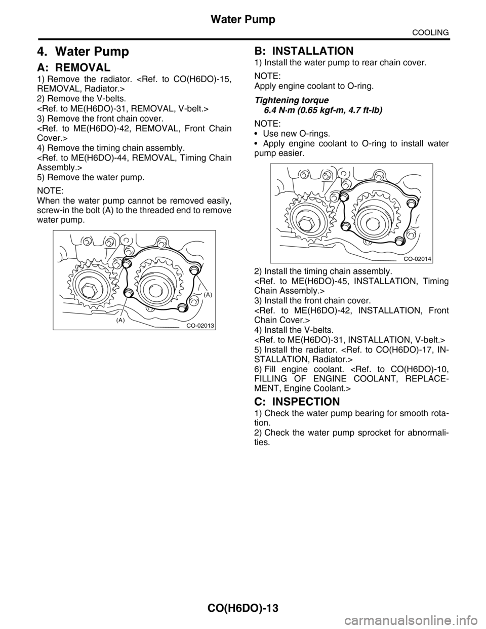
NOTE:
When the water pump cannot be removed easily,
screw-in the bolt (A) to the threaded end to remove
water pump.
B: INSTALLATION
1) Install the water pump to rear chain cover.
NOTE:
Apply engine coolant to O-ring.
Tightening torque
6.4 N·m (0.65 kgf-m, 4.7 ft-lb)
NOTE:
•Use new O-rings.
•Apply engine coolant to O-ring to install water
pump easier.
2) Install the timing chain assembly.
3) Install the front chain cover.
4) Install the V-belts.
5) Install the radiator.
6) Fill engine coolant.
MENT, Engine Coolant.>
C: INSPECTION
1) Check the water pump bearing for smooth rota-
tion.
2) Check the water pump sprocket for abnormali-
ties.
CO-02013
(A)
(A)
CO-02014
Page 1238 of 2453
EN(H6DO)(diag)-77
Diagnostic Procedure with Diagnostic Trouble Code (DTC)
ENGINE (DIAGNOSTICS)
18.Diagnostic Procedure with Diagnostic Trouble Code (DTC)
A: DTC P0011 INTAKE CAMSHAFT POSITION TIMING - OVER-ADVANCED
(BANK 1)
DTC DETECTING CONDITION:
•Detected when two consecutive driving cycles with fault occur.
•GENERAL DESCRIPTION
TROUBLE SYMPTOM:
•Engine stalls.
•Erroneous idling
CAUTION:
After repair or replacement of faulty parts, perform Clear Memory Mode
Step Check Yes No
1CHECK ANY OTHER DTC ON DISPLAY.Is any other DTC displayed? Inspect the rele-
vant DTC using
“List of Diagnostic
Tr o u b l e C o d e
(DTC).”
69, List of Diag-
nostic Trouble
Code (DTC).>
Go to step 2.
2CHECK CURRENT DATA.
1) Start the engine and let it idle.
2) Measure the AVCS system operating angle
and oil flow control solenoid valve duty output
using Subaru Select Monitor or general scan
tool.
NOTE:•Subaru Select Monitor
For detailed operation procedures, refer to
“READ CURRENT DATA FOR ENGINE”.
tor.>
•General scan tool
For detailed operation procedure, refer to the
general scan tool operation manual.
Is the AVCS system operating
angle approx. 0 deg., and oil
flow control solenoid valve duty
output approx. 10%?
Check the follow-
ing item and repair
or replace if nec-
essary.
•Oil pipe (clog)
•Oil flow con-
trol solenoid
valve (clog or
dirt of oil rout-
ing, setting of
spring, clog of
valve)
•Intake cam-
shaft (dirt, dam-
age of
camshaft)
•Timing chain
(matching of
timing mark)
A temporary mal-
function. Perform
the following, and
clean the oil rout-
ing.
Replace the
engine oil and idle
the engine for 5
minutes, and then
replace the oil filter
and engine oil.
Page 1239 of 2453
EN(H6DO)(diag)-78
Diagnostic Procedure with Diagnostic Trouble Code (DTC)
ENGINE (DIAGNOSTICS)
B: DTC P0016 CRANKSHAFT POSITION - CAMSHAFT POSITION CORRELA-
TION (BANK 1)
DTC DETECTING CONDITION:
•Detected when two consecutive driving cycles with fault occur.
•GENERAL DESCRIPTION
TROUBLE SYMPTOM:
•Engine stalls.
•Erroneous idling
CAUTION:
After repair or replacement of faulty parts, perform Clear Memory Mode
Step Check Yes No
1CHECK ANY OTHER DTC ON DISPLAY.Is any other DTC displayed? Inspect the rele-
vant DTC using
“List of Diagnostic
Tr o u b l e C o d e
(DTC).”
69, List of Diag-
nostic Trouble
Code (DTC).>
Go to step 2.
2CHECK CURRENT DATA.
1) Start the engine and let it idle.
2) Measure the AVCS system operating angle
and oil flow control solenoid valve duty output
using Subaru Select Monitor or general scan
tool.
NOTE:•Subaru Select Monitor
For detailed operation procedures, refer to
“READ CURRENT DATA FOR ENGINE”.
tor.>
•General scan tool
For detailed operation procedure, refer to the
general scan tool operation manual.
Is the AVCS system operating
angle approx. 0 deg., and oil
flow control solenoid valve duty
output approx. 10%?
Check the follow-
ing item and repair
or replace if nec-
essary.
•Oil pipe (clog)
•Oil flow con-
trol solenoid
valve (clog or
dirt of oil rout-
ing, setting of
spring, clog of
valve)
•Intake cam-
shaft (dirt, dam-
age of
camshaft)
•Timing chain
(matching of
timing mark)
A temporary mal-
function. Perform
the following, and
clean the oil rout-
ing.
Replace the
engine oil and idle
the engine for 5
minutes, and then
replace the oil filter
and engine oil.
Page 1240 of 2453
EN(H6DO)(diag)-79
Diagnostic Procedure with Diagnostic Trouble Code (DTC)
ENGINE (DIAGNOSTICS)
C: DTC P0018 CRANKSHAFT POSITION - CAMSHAFT POSITION CORRELA-
TION (BANK 2)
DTC DETECTING CONDITION:
•Detected when two consecutive driving cycles with fault occur.
•GENERAL DESCRIPTION
TROUBLE SYMPTOM:
•Engine stalls.
•Erroneous idling
CAUTION:
After repair or replacement of faulty parts, perform Clear Memory Mode
Step Check Yes No
1CHECK ANY OTHER DTC ON DISPLAY.Is any other DTC displayed? Check the appro-
priate DTC using
the “List of Diag-
nostic Trouble
Code (DTC)”.
69, List of Diag-
nostic Trouble
Code (DTC).>
Go to step 2.
2CHECK CURRENT DATA.
1) Start the engine and let it idle.
2) Check the AVCS system operating angle
and oil flow control solenoid valve duty output
using Subaru Select Monitor or general scan
tool.
NOTE:
•Subaru Select Monitor
For detailed operation procedures, refer to
“READ CURRENT DATA FOR ENGINE”.
tor.>
•General scan tool
For detailed operation procedure, refer to the
general scan tool operation manual.
Is the AVCS system operating
angle approx. 0 deg., and oil
flow control solenoid valve duty
output approx. 10%?
Check the follow-
ing item and repair
or replace if nec-
essary.
•Engine oil
(amount, dirt)
•Oil pipe (clog)
•Oil flow con-
trol solenoid
valve (clog or
dirt of oil rout-
ing, setting of
spring, clog of
valve)
•Intake cam-
shaft (dirt, dam-
age of
camshaft)
•Timing chain
(matching of
timing mark)
A temporary mal-
function. Perform
the following, and
clean the oil rout-
ing.
Replace the
engine oil and idle
the engine for 5
minutes, and then
replace the oil filter
and engine oil.
Page 1241 of 2453
EN(H6DO)(diag)-80
Diagnostic Procedure with Diagnostic Trouble Code (DTC)
ENGINE (DIAGNOSTICS)
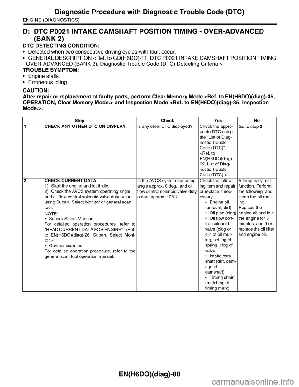
D: DTC P0021 INTAKE CAMSHAFT POSITION TIMING - OVER-ADVANCED
(BANK 2)
DTC DETECTING CONDITION:
•Detected when two consecutive driving cycles with fault occur.
•GENERAL DESCRIPTION
TROUBLE SYMPTOM:
•Engine stalls.
•Erroneous idling
CAUTION:
After repair or replacement of faulty parts, perform Clear Memory Mode
Step Check Yes No
1CHECK ANY OTHER DTC ON DISPLAY.Is any other DTC displayed? Check the appro-
priate DTC using
the “List of Diag-
nostic Trouble
Code (DTC)”.
69, List of Diag-
nostic Trouble
Code (DTC).>
Go to step 2.
2CHECK CURRENT DATA.
1) Start the engine and let it idle.
2) Check the AVCS system operating angle
and oil flow control solenoid valve duty output
using Subaru Select Monitor or general scan
tool.
NOTE:
•Subaru Select Monitor
For detailed operation procedures, refer to
“READ CURRENT DATA FOR ENGINE”.
tor.>
•General scan tool
For detailed operation procedure, refer to the
general scan tool operation manual.
Is the AVCS system operating
angle approx. 0 deg., and oil
flow control solenoid valve duty
output approx. 10%?
Check the follow-
ing item and repair
or replace if nec-
essary.
•Engine oil
(amount, dirt)
•Oil pipe (clog)
•Oil flow con-
trol solenoid
valve (clog or
dirt of oil rout-
ing, setting of
spring, clog of
valve)
•Intake cam-
shaft (dirt, dam-
age of
camshaft)
•Timing chain
(matching of
timing mark)
A temporary mal-
function. Perform
the following, and
clean the oil rout-
ing.
Replace the
engine oil and idle
the engine for 5
minutes, and then
replace the oil filter
and engine oil.
Page 1407 of 2453
EN(H6DO)(diag)-246
Diagnostic Procedure with Diagnostic Trouble Code (DTC)
ENGINE (DIAGNOSTICS)
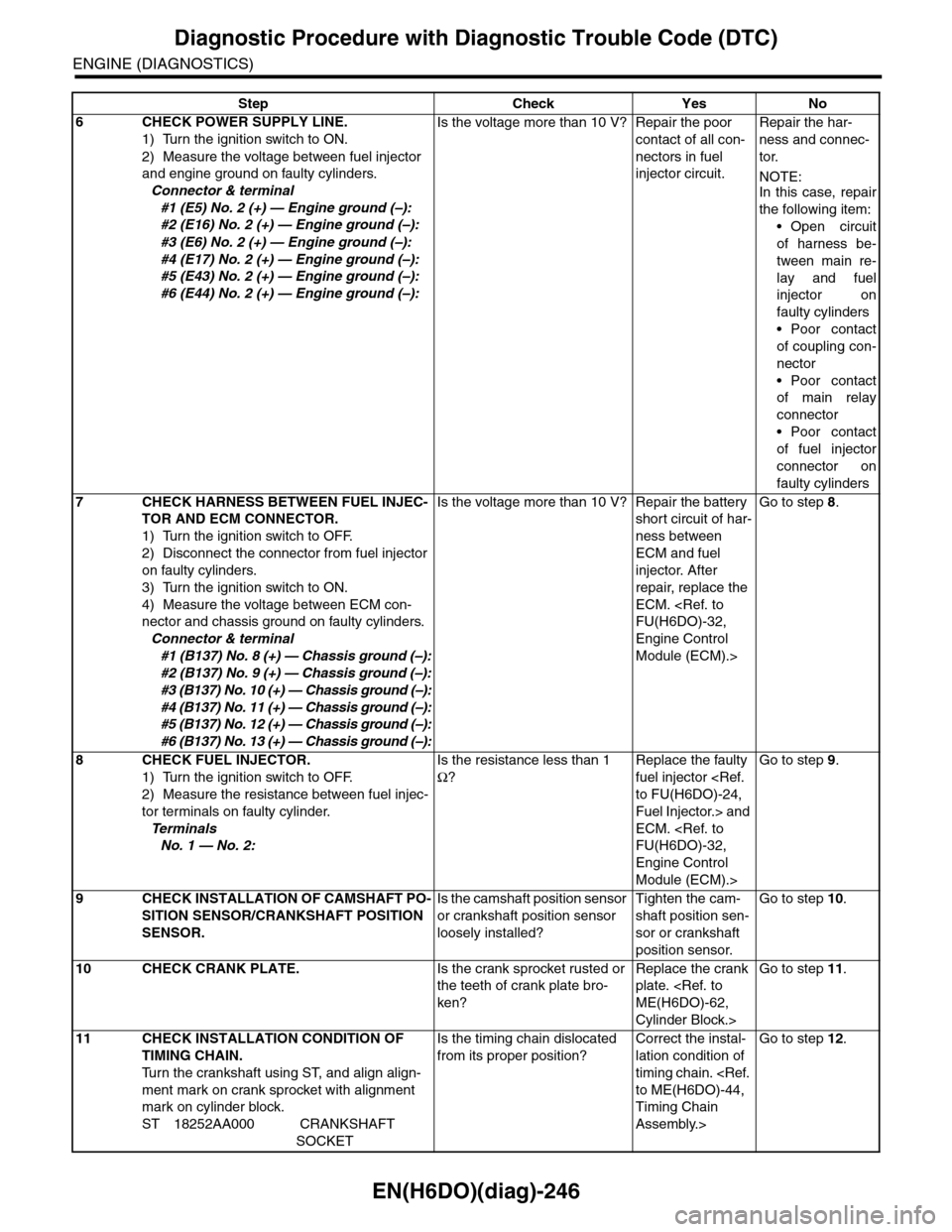
6CHECK POWER SUPPLY LINE.
1) Turn the ignition switch to ON.
2) Measure the voltage between fuel injector
and engine ground on faulty cylinders.
Connector & terminal
#1 (E5) No. 2 (+) — Engine ground (–):
#2 (E16) No. 2 (+) — Engine ground (–):
#3 (E6) No. 2 (+) — Engine ground (–):
#4 (E17) No. 2 (+) — Engine ground (–):
#5 (E43) No. 2 (+) — Engine ground (–):
#6 (E44) No. 2 (+) — Engine ground (–):
Is the voltage more than 10 V? Repair the poor
contact of all con-
nectors in fuel
injector circuit.
Repair the har-
ness and connec-
tor.
NOTE:In this case, repair
the following item:
•Open circuit
of harness be-
tween main re-
lay and fuel
injector on
faulty cylinders
•Poor contact
of coupling con-
nector
•Poor contact
of main relay
connector
•Poor contact
of fuel injector
connector on
faulty cylinders
7CHECK HARNESS BETWEEN FUEL INJEC-
TOR AND ECM CONNECTOR.
1) Turn the ignition switch to OFF.
2) Disconnect the connector from fuel injector
on faulty cylinders.
3) Turn the ignition switch to ON.
4) Measure the voltage between ECM con-
nector and chassis ground on faulty cylinders.
Connector & terminal
#1 (B137) No. 8 (+) — Chassis ground (–):
#2 (B137) No. 9 (+) — Chassis ground (–):
#3 (B137) No. 10 (+) — Chassis ground (–):
#4 (B137) No. 11 (+) — Chassis ground (–):
#5 (B137) No. 12 (+) — Chassis ground (–):
#6 (B137) No. 13 (+) — Chassis ground (–):
Is the voltage more than 10 V? Repair the battery
short circuit of har-
ness between
ECM and fuel
injector. After
repair, replace the
ECM.
Engine Control
Module (ECM).>
Go to step 8.
8CHECK FUEL INJECTOR.
1) Turn the ignition switch to OFF.
2) Measure the resistance between fuel injec-
tor terminals on faulty cylinder.
Te r m i n a l s
No. 1 — No. 2:
Is the resistance less than 1
Ω?
Replace the faulty
fuel injector
Fuel Injector.> and
ECM.
Engine Control
Module (ECM).>
Go to step 9.
9CHECK INSTALLATION OF CAMSHAFT PO-
SITION SENSOR/CRANKSHAFT POSITION
SENSOR.
Is the camshaft position sensor
or crankshaft position sensor
loosely installed?
Tighten the cam-
shaft position sen-
sor or crankshaft
position sensor.
Go to step 10.
10 CHECK CRANK PLATE.Is the crank sprocket rusted or
the teeth of crank plate bro-
ken?
Replace the crank
plate.
Cylinder Block.>
Go to step 11.
11 CHECK INSTALLATION CONDITION OF
TIMING CHAIN.
Tu r n t h e c r a n k s h a f t u s i n g S T, a n d a l i g n a l i g n -
ment mark on crank sprocket with alignment
mark on cylinder block.
ST 18252AA000 CRANKSHAFT
SOCKET
Is the timing chain dislocated
from its proper position?
Correct the instal-
lation condition of
timing chain.
Timing Chain
Assembly.>
Go to step 12.
Step Check Yes No
Page 1423 of 2453
EN(H6DO)(diag)-262
Diagnostic Procedure with Diagnostic Trouble Code (DTC)
ENGINE (DIAGNOSTICS)
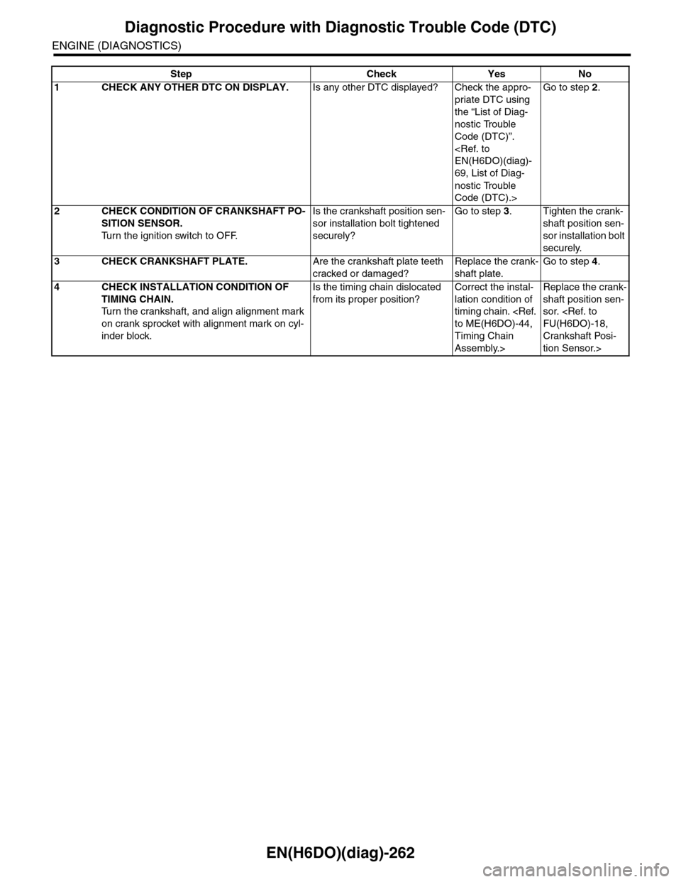
Step Check Yes No
1CHECK ANY OTHER DTC ON DISPLAY.Is any other DTC displayed? Check the appro-
priate DTC using
the “List of Diag-
nostic Trouble
Code (DTC)”.
69, List of Diag-
nostic Trouble
Code (DTC).>
Go to step 2.
2CHECK CONDITION OF CRANKSHAFT PO-
SITION SENSOR.
Tu r n t h e i g n i t i o n s w i t c h t o O F F.
Is the crankshaft position sen-
sor installation bolt tightened
securely?
Go to step 3.Tighten the crank-
shaft position sen-
sor installation bolt
securely.
3CHECK CRANKSHAFT PLATE.Are the crankshaft plate teeth
cracked or damaged?
Replace the crank-
shaft plate.
Go to step 4.
4CHECK INSTALLATION CONDITION OF
TIMING CHAIN.
Tu r n t h e c r a n k s h a f t , a n d a l i g n a l i g n m e n t m a r k
on crank sprocket with alignment mark on cyl-
inder block.
Is the timing chain dislocated
from its proper position?
Correct the instal-
lation condition of
timing chain.
Timing Chain
Assembly.>
Replace the crank-
shaft position sen-
sor.
Crankshaft Posi-
tion Sensor.>
Page 1857 of 2453
LU(H6DO)-8
Oil Pump
LUBRICATION
4. Oil Pump
A: REMOVAL
1) Remove the collector cover.
2) Disconnect the ground cable from battery.
3) Lift-up the vehicle.
4) Remove the under cover.
5) Drain engine coolant.
MENT, Engine Coolant.>
6) Lower the vehicle.
7) Remove the radiator.
8) Remove the V-belts.
9) Remove the front chain cover.
10) Remove the timing chain.
11) Remove the crank sprocket.
12) Remove the oil pump cover.
13) Remove the inner rotor and outer rotor.
B: INSTALLATION
1) Apply a coat of engine oil to the whole area of in-
ner rotor and outer rotor.
2) Set the inner rotor onto opening edge of crank
shaft, and install the inner rotor, and then assemble
the outer rotor.
3) Install the oil pump cover.
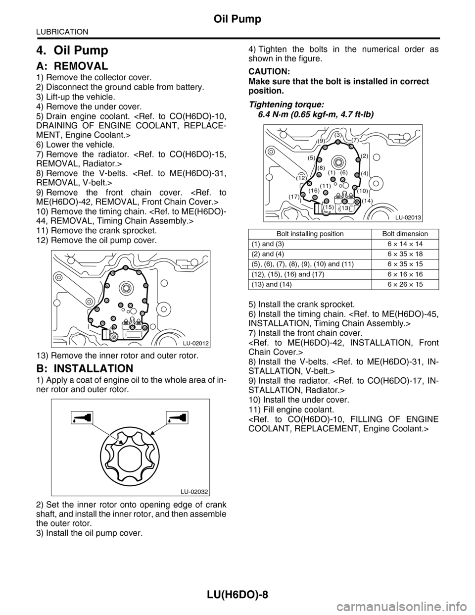
4) Tighten the bolts in the numerical order as
shown in the figure.
CAUTION:
Make sure that the bolt is installed in correct
position.
Tightening torque:
6.4 N·m (0.65 kgf-m, 4.7 ft-lb)
5) Install the crank sprocket.
6) Install the timing chain.
7) Install the front chain cover.
8) Install the V-belts.
9) Install the radiator.
10) Install the under cover.
11) Fill engine coolant.
LU-02012
LU-02032
Bolt installing position Bolt dimension
(1) and (3) 6 × 14 × 14
(2) and (4) 6 × 35 × 18
(5), (6), (7), (8), (9), (10) and (11) 6 × 35 × 15
(12), (15), (16) and (17) 6 × 16 × 16
(13) and (14) 6 × 26 × 15
LU-02013
(3)(7)
(2)
(4)
(9)
(5)
(8)(1)(6)(12)
(13)(14)(15)
(16)(17)
(11)(10)