2009 SUBARU TRIBECA driver window
[x] Cancel search: driver windowPage 276 of 2453

EI-34
Roof Molding
EXTERIOR/INTERIOR TRIM
11.Roof Molding
A: REMOVAL
1) Turn over the edge of the roof molding, and re-
move the inside clips with flat tip screwdriver by
sliding as arrow indicates.
Right side: slide towards the front of the vehicle.
Left side: slide towards the rear of the vehicle.
2) Pull the roof molding upward, and remove it from
vehicle body.
3) Remove the roof trim.
4) Remove the nuts, and remove the roof carrier at-
tachment.
B: INSTALLATION
1) Install the roof carrier attachment.
Tightening torque:
7.5 N·m (0.77 kgf-m, 5.53 ft-lb)
2) Remove each clip from the roof molding, and in-
stall them to the vehicle side.
CAUTION:
Always replace clips damaged during removal
of the roof moulding with new clips.
3) Push the front edge of roof molding against the
front window, and install the positioning clip on the
front end to the rivet on the vehicle side.
EI-00509
EI-01380
(1) Windshield
(2) Positioning clips
(3) Roof molding
(4) Rivet
(5) Clip
EI-00659
EI-01381
(2)
(1)
(4)(5)
(3)
Page 303 of 2453
GW-8
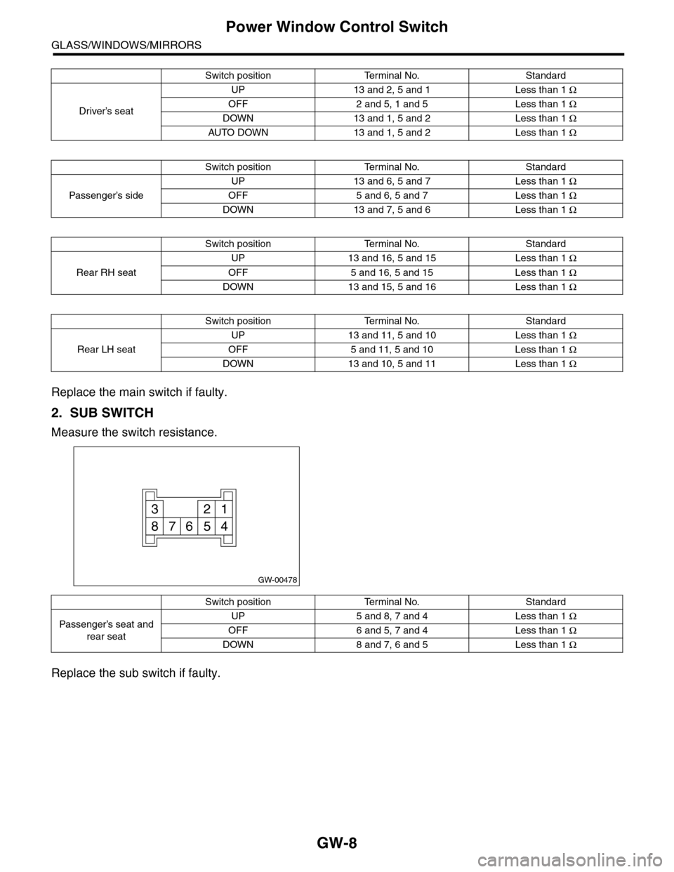
Power Window Control Switch
GLASS/WINDOWS/MIRRORS
Replace the main switch if faulty.
2. SUB SWITCH
Measure the switch resistance.
Replace the sub switch if faulty.
Switch positionTerminal No.Standard
Driver’s seat
UP 13 and 2, 5 and 1 Less than 1 Ω
OFF 2 and 5, 1 and 5 Less than 1 Ω
DOWN 13 and 1, 5 and 2 Less than 1 Ω
AUTO DOWN 13 and 1, 5 and 2 Less than 1 Ω
Switch positionTerminal No.Standard
Passenger’s side
UP 13 and 6, 5 and 7 Less than 1 Ω
OFF 5 and 6, 5 and 7 Less than 1 Ω
DOWN 13 and 7, 5 and 6 Less than 1 Ω
Switch positionTerminal No.Standard
Rear RH seat
UP 13 and 16, 5 and 15 Less than 1 Ω
OFF 5 and 16, 5 and 15 Less than 1 Ω
DOWN 13 and 15, 5 and 16 Less than 1 Ω
Switch positionTerminal No.Standard
Rear LH seat
UP 13 and 11, 5 and 10 Less than 1 Ω
OFF 5 and 11, 5 and 10 Less than 1 Ω
DOWN 13 and 10, 5 and 11 Less than 1 Ω
GW-00478
123
45678
Switch positionTerminal No.Standard
Passenger’s seat and
rear seat
UP 5 and 8, 7 and 4 Less than 1 Ω
OFF 6 and 5, 7 and 4 Less than 1 Ω
DOWN 8 and 7, 6 and 5 Less than 1 Ω
Page 309 of 2453

GW-14
Outer Mirror
GLASS/WINDOWS/MIRRORS
9. Outer Mirror
A: REPLACEMENT
1) Face the mirror upward.
2) Use a flat tip screwdriver to remove clip (A).
3) Lift the lower mirror up to remove hooks (B).
4) Disconnect the mirror heater connector from
side of the mirror. (Model with mirror heater)
5) Catch the hooks (B) and install clips (A).
CAUTION:
•When removing the mirror, be careful not to
damage the back surface of mirror with a flat tip
screwdriver.
•When installing the mirror, insert the hook
and clip securely.
(A)
GW-00279
(B)
GW-00280
(B)
GW-00450(A)
Page 641 of 2453
SL-12
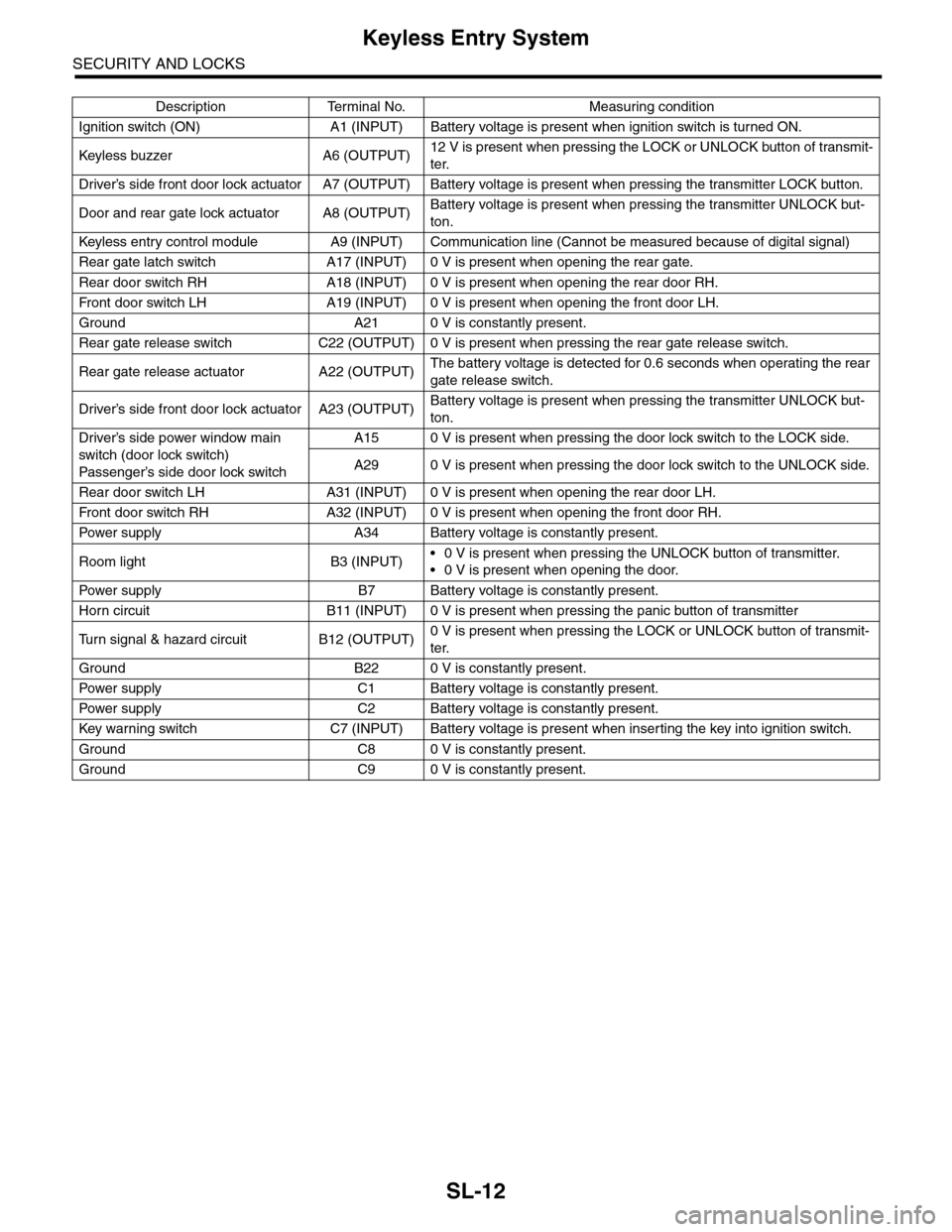
Keyless Entry System
SECURITY AND LOCKS
Description Terminal No. Measuring condition
Ignition switch (ON) A1 (INPUT) Battery voltage is present when ignition switch is turned ON.
Keyless buzzer A6 (OUTPU T)12 V is present when pressing the LOCK or UNLOCK button of transmit-
ter.
Driver’s side front door lock actuator A7 (OUTPUT) Battery voltage is present when pressing the transmitter LOCK button.
Door and rear gate lock actuator A8 (OUTPUT)Battery voltage is present when pressing the transmitter UNLOCK but-
ton.
Keyless entr y control module A9 (INPUT) Communication line (Cannot be measured because of digital signal)
Rear gate latch switch A17 (INPUT) 0 V is present when opening the rear gate.
Rear door switch RH A18 (INPUT) 0 V is present when opening the rear door RH.
Fr o nt d oo r swi tc h L H A 19 ( I NP UT ) 0 V i s pr e se n t wh e n o p en in g th e f r o n t d oo r L H.
Ground A21 0 V is constantly present.
Rear gate release switch C22 (OUTPUT) 0 V is present when pressing the rear gate release switch.
Rear gate release actuator A22 (OUTPUT)The battery voltage is detected for 0.6 seconds when operating the rear
gate release switch.
Driver’s side front door lock actuator A23 (OUTPUT)Battery voltage is present when pressing the transmitter UNLOCK but-
ton.
Driver’s side power window main
switch (door lock switch)
Passenger’s side door lock sw itch
A15 0 V is present when pressing the door lock switch to the LOCK side.
A29 0 V is present when pressing the door lock switch to the UNLOCK side.
Rear door switch LH A31 (INPUT) 0 V is present when opening the rear door LH.
Fr o nt d oo r swi tc h RH A 32 ( I NP UT ) 0 V i s pr e se n t wh e n o p en in g th e f r o n t d oo r RH.
Pow er s up p ly A 34 B at t e r y vol t ag e i s c on s ta n tl y p r e se nt .
Room light B3 (INPUT)•0 V is present when pressing the UNLOCK button of transmitter.
•0 V is present when opening the door.
Pow er s up p ly B 7 B at t e r y vol t ag e i s c on s ta n tl y p r e se nt .
Horn circuit B11 (INPUT) 0 V is present when pressing the panic button of transmitter
Tu r n s i g n a l & h a z a r d c i r c u i t B 1 2 ( O U T P U T )0 V is present when pressing the LOCK or UNLOCK button of transmit-
ter.
Ground B22 0 V is constantly present.
Pow er s up p ly C 1 B at t e r y vol t ag e i s c on s ta n tl y p r e se nt .
Pow er s up p ly C 2 B at t e r y vol t ag e i s c on s ta n tl y p r e se nt .
Key war ning switch C7 (INPUT) Batter y voltage is present when inser ting the key into ignition switch.
Ground C8 0 V is constantly present.
Ground C9 0 V is constantly present.
Page 710 of 2453
WW-15
Front Wiper Arm
WIPER AND WASHER SYSTEMS
7. Front Wiper Arm
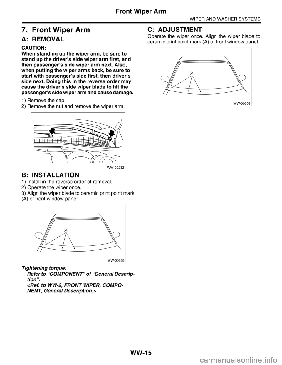
A: REMOVAL
CAUTION:
When standing up the wiper arm, be sure to
stand up the driver’s side wiper arm first, and
then passenger’s side wiper arm next. Also,
when putting the wiper arms back, be sure to
start with passenger’s side first, then driver’s
side next. Doing this in the reverse order may
cause the driver’s side wiper blade to hit the
passenger’s side wiper arm and cause damage.
1) Remove the cap.
2) Remove the nut and remove the wiper arm.
B: INSTALLATION
1) Install in the reverse order of removal.
2) Operate the wiper once.
3) Align the wiper blade to ceramic print point mark
(A) of front window panel.
Tightening torque:
Refer to “COMPONENT” of “General Descrip-
tion”.
C: ADJUSTMENT
Operate the wiper once. Align the wiper blade to
ceramic print point mark (A) of front window panel.
WW-00232
WW-00359
(A)
WW-00359
(A)
Page 2104 of 2453
5AT-88
Front Differential Assembly
AUTOMATIC TRANSMISSION
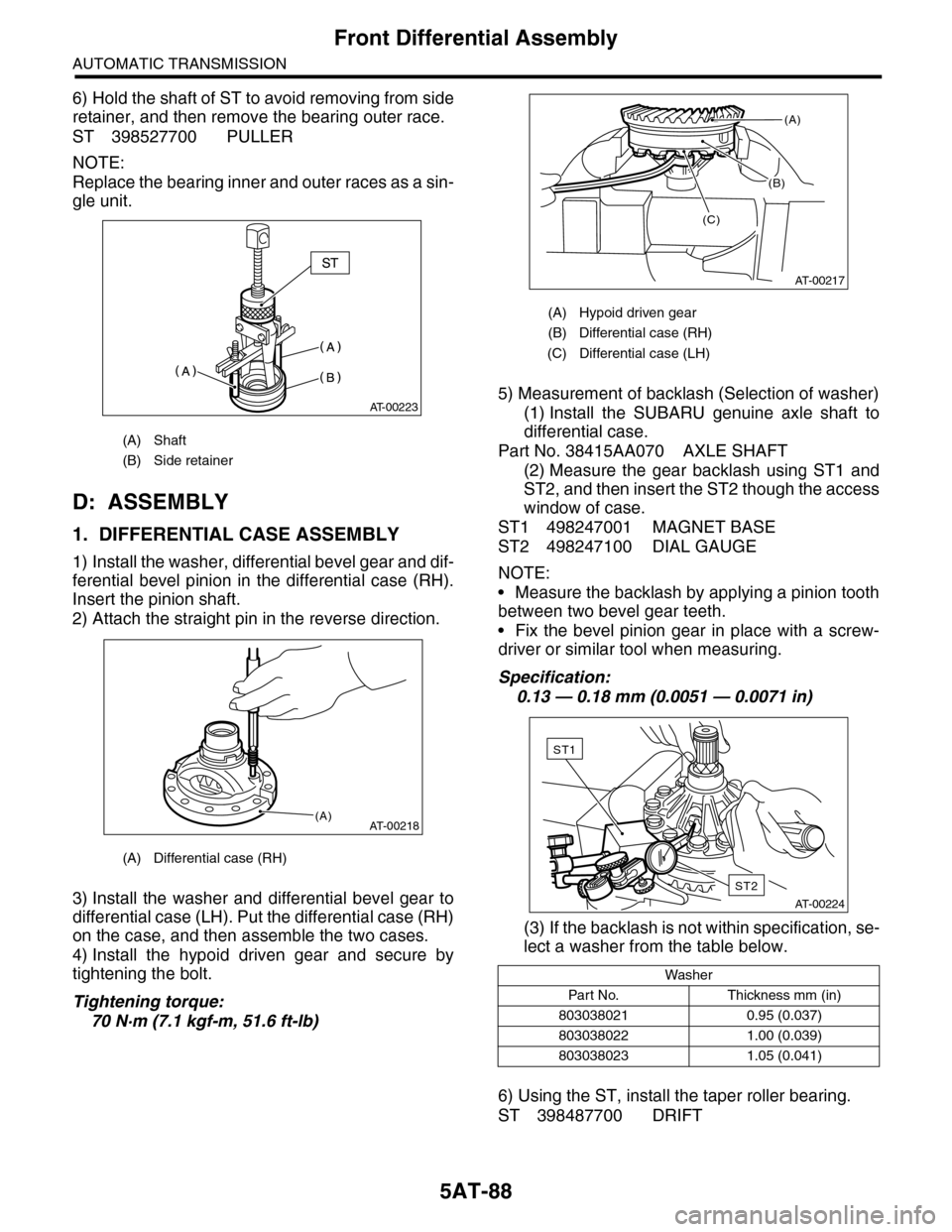
6) Hold the shaft of ST to avoid removing from side
retainer, and then remove the bearing outer race.
ST 398527700 PULLER
NOTE:
Replace the bearing inner and outer races as a sin-
gle unit.
D: ASSEMBLY
1. DIFFERENTIAL CASE ASSEMBLY
1) Install the washer, differential bevel gear and dif-
ferential bevel pinion in the differential case (RH).
Insert the pinion shaft.
2) Attach the straight pin in the reverse direction.
3) Install the washer and differential bevel gear to
differential case (LH). Put the differential case (RH)
on the case, and then assemble the two cases.
4) Install the hypoid driven gear and secure by
tightening the bolt.
Tightening torque:
70 N·m (7.1 kgf-m, 51.6 ft-lb)
5) Measurement of backlash (Selection of washer)
(1) Install the SUBARU genuine axle shaft to
differential case.
Part No. 38415AA070 AXLE SHAFT
(2) Measure the gear backlash using ST1 and
ST2, and then insert the ST2 though the access
window of case.
ST1 498247001 MAGNET BASE
ST2 498247100 DIAL GAUGE
NOTE:
•Measure the backlash by applying a pinion tooth
between two bevel gear teeth.
•Fix the bevel pinion gear in place with a screw-
driver or similar tool when measuring.
Specification:
0.13 — 0.18 mm (0.0051 — 0.0071 in)
(3) If the backlash is not within specification, se-
lect a washer from the table below.
6) Using the ST, install the taper roller bearing.
ST 398487700 DRIFT
(A) Shaft
(B) Side retainer
(A) Differential case (RH)
AT-00223
AT-00218(A)
(A) Hypoid driven gear
(B) Differential case (RH)
(C) Differential case (LH)
Washer
Par t N o. Thickness mm (in)
803038021 0.95 (0.037)
803038022 1.00 (0.039)
803038023 1.05 (0.041)
(B)
AT-00217
(A)
(C)
AT-00224
ST2
ST1
Page 2304 of 2453
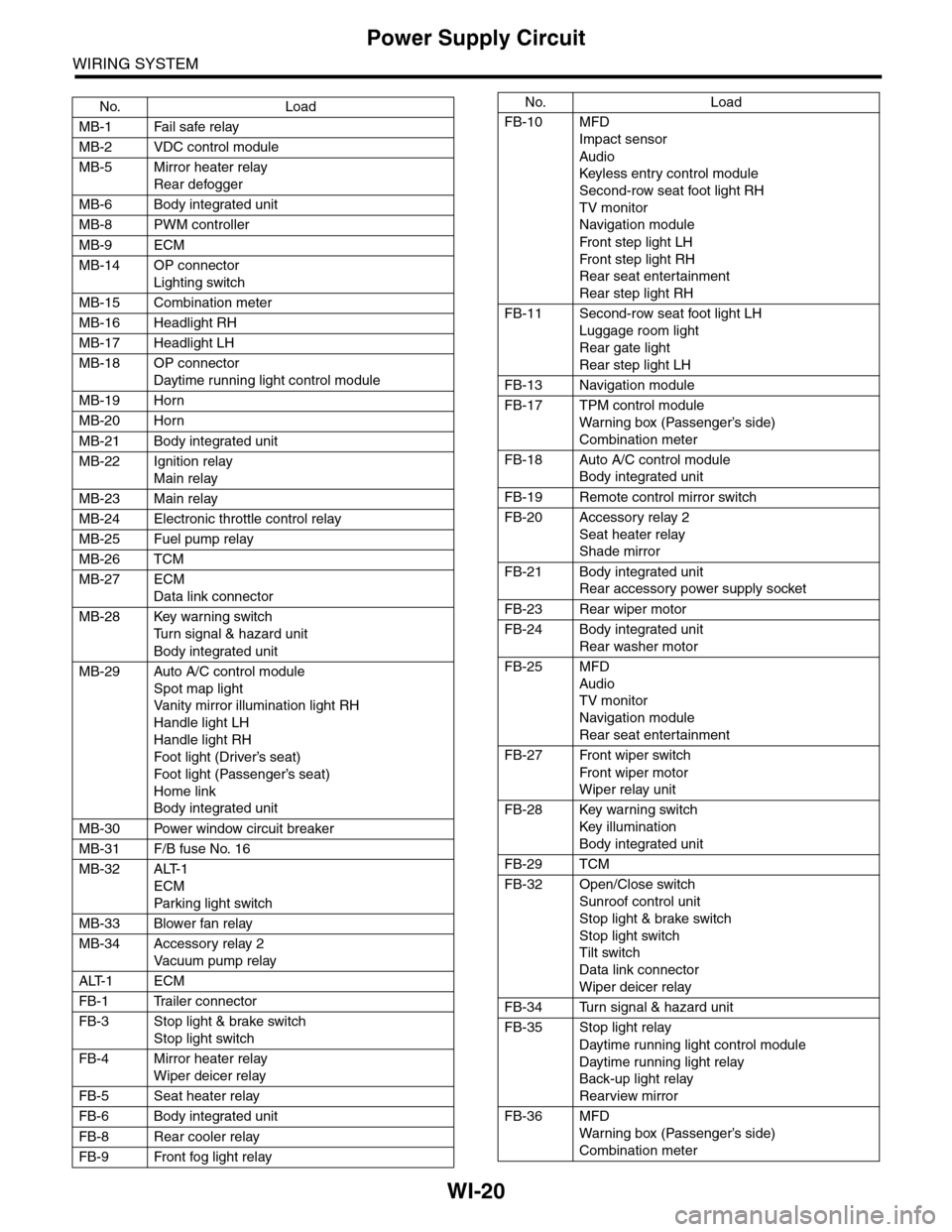
WI-20
Power Supply Circuit
WIRING SYSTEM
No. Load
MB-1 Fail safe relay
MB-2 VDC control module
MB-5 Mirror heater relay
Rear defogger
MB-6 Body integrated unit
MB-8 PWM controller
MB-9 ECM
MB-14 OP connector
Lighting switch
MB-15 Combination meter
MB-16 Headlight RH
MB-17 Headlight LH
MB-18 OP connector
Daytime running light control module
MB-19 Horn
MB-20 Horn
MB-21 Body integrated unit
MB-22 Ignition relay
Main relay
MB-23 Main relay
MB-24 Electronic throttle control relay
MB-25 Fuel pump relay
MB-26 TCM
MB-27 ECM
Data link connector
MB-28 Key warning switch
Tu r n s i g n a l & h a z a r d u n i t
Body integrated unit
MB-29 Auto A/C control module
Spot map light
Va n i t y m i r r o r i l l u m i n a t i o n l i g h t R H
Handle light LH
Handle light RH
Foot light (Driver’s seat)
Foot light (Passenger’s seat)
Home link
Body integrated unit
MB-30 Power window circuit breaker
MB-31 F/B fuse No. 16
MB-32 ALT-1
ECM
Par king light switch
MB-33 Blower fan relay
MB-34 Accessory relay 2
Va c u u m p u m p r e l ay
ALT-1 ECM
FB-1 Trailer connector
FB-3 Stop light & brake switch
Stop light switch
FB-4 Mirror heater relay
Wiper deicer relay
FB-5 Seat heater relay
FB-6 Body integrated unit
FB-8 Rear cooler relay
FB-9 Front fog light relay
FB-10 MFD
Impact sensor
Audio
Keyless entr y control module
Second-row seat foot light RH
TV monitor
Navigation module
Fr o n t s te p li gh t LH
Fr o n t s te p li gh t RH
Rear seat entertainment
Rear step light RH
FB-11 Second-row seat foot light LH
Luggage room light
Rear gate light
Rear step light LH
FB-13 Navigation module
FB-17 TPM control module
War ning box (Passenger’s side)
Combination meter
FB-18 Auto A/C control module
Body integrated unit
FB-19 Remote control mirror switch
FB-20 Accessory relay 2
Seat heater relay
Shade mirror
FB-21 Body integrated unit
Rear accessory power supply socket
FB-23 Rear wiper motor
FB-24 Body integrated unit
Rear washer motor
FB-25 MFD
Audio
TV monitor
Navigation module
Rear seat entertainment
FB-27 Front wiper switch
Fr o n t wi p er mo t or
Wiper relay unit
FB-28 Key warning switch
Key illumination
Body integrated unit
FB-29 TCM
FB-32 Open/Close switch
Sunroof control unit
Stop light & brake switch
Stop light switch
Tilt switch
Data link connector
Wiper deicer relay
FB-34 Turn signal & hazard unit
FB-35 Stop light relay
Daytime running light control module
Daytime running light relay
Back-up light relay
Rearview mirror
FB-36 MFD
War ning box (Passenger’s side)
Combination meter
No. Load
Page 2310 of 2453
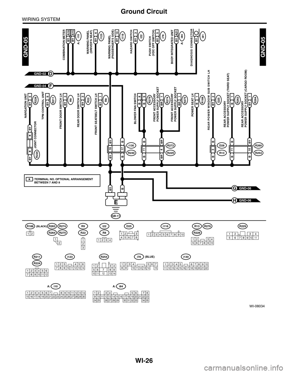
WI-26
Ground Circuit
WIRING SYSTEM
WI-08034
GND-05GND-05
GND-06G
GND-06H
(BLACK)R188
B A16
COMBINATION METER
GND-02D
GND-04F
GB-11
BBY
BY A16BY A15BY 2
A21
BODY INTEGRATED UNIT
i78BY 2
5
PUSH SWITCH(VDC OFF SWITCH)
i22BY 2
3
HAZARD SWITCH
i116BY 2
10
WARNING PANEL (PASSENGER'S SIDE)
R8BY 2
1
FRONT SEATBELT SWITCH LH
R22BY 2
3
REAR DOOR SWITCH LH
R9BY
3
FRONT DOOR SWITCH LH
R211BY
9
TPM CONTROL UNIT
R226BY
6
NAVIGATION UNIT
R264BY 2
1
REAR ACCESSORY POWER SUPPLY SOCKET (CARGO ROOM)
R263B2
1
REAR ACCESSORY POWER SUPPLY SOCKET (THIRD SEAT)
D25BY
2
REAR POWER WINDOW SUB SWITCH LH
R188B
1
POWER SEAT LH
R275BR
1
R274BR
1
FRONT ACCESSORY POWER SUPPLY SOCKETFRONT ACCESSORY POWER SUPPLY SOCKET
i123BY 2
6
WARNING PANEL (DRIVER'S SEAT)
A:
i10
B A16
BLOWER FAN SWITCH
B8B9R276
A:
i84
i130
R230
B
1716
B
BY
BY
R272
R229
BR
411
BR
B
B
R260
R254
BY
1011
B
B
B
D28
R13
B
3
B
i81BY
DIAGNOSIS CONNECTOR
R224
JOINT CONNECTOR
*
*
BY
BY
*:TERMINAL NO. OPTIONAL ARRANGEMENT BETWEEN 7 AND 8
1234
i116
12345678910
i10
19 20 2115 16 17 182223242526272829301234568910 11 12 13 147
A:
R8
i22
123
R22
R9
12
12345678910
A: i84
1234567891011121415161718192021222324252627282930313233343513
123456789101112
R224
R211
R226
R13R276
R264
R263R274
R275
R254
12
10115634897131412
R229
8791012543611
D25
12345678
123 8910411 12 13 14 15 16567171819202122
i130i123
123 45678910 11 12 13 14
i78
123456789101112131415
(BLUE)
12