2009 SUBARU TRIBECA oil filter
[x] Cancel search: oil filterPage 1238 of 2453
EN(H6DO)(diag)-77
Diagnostic Procedure with Diagnostic Trouble Code (DTC)
ENGINE (DIAGNOSTICS)
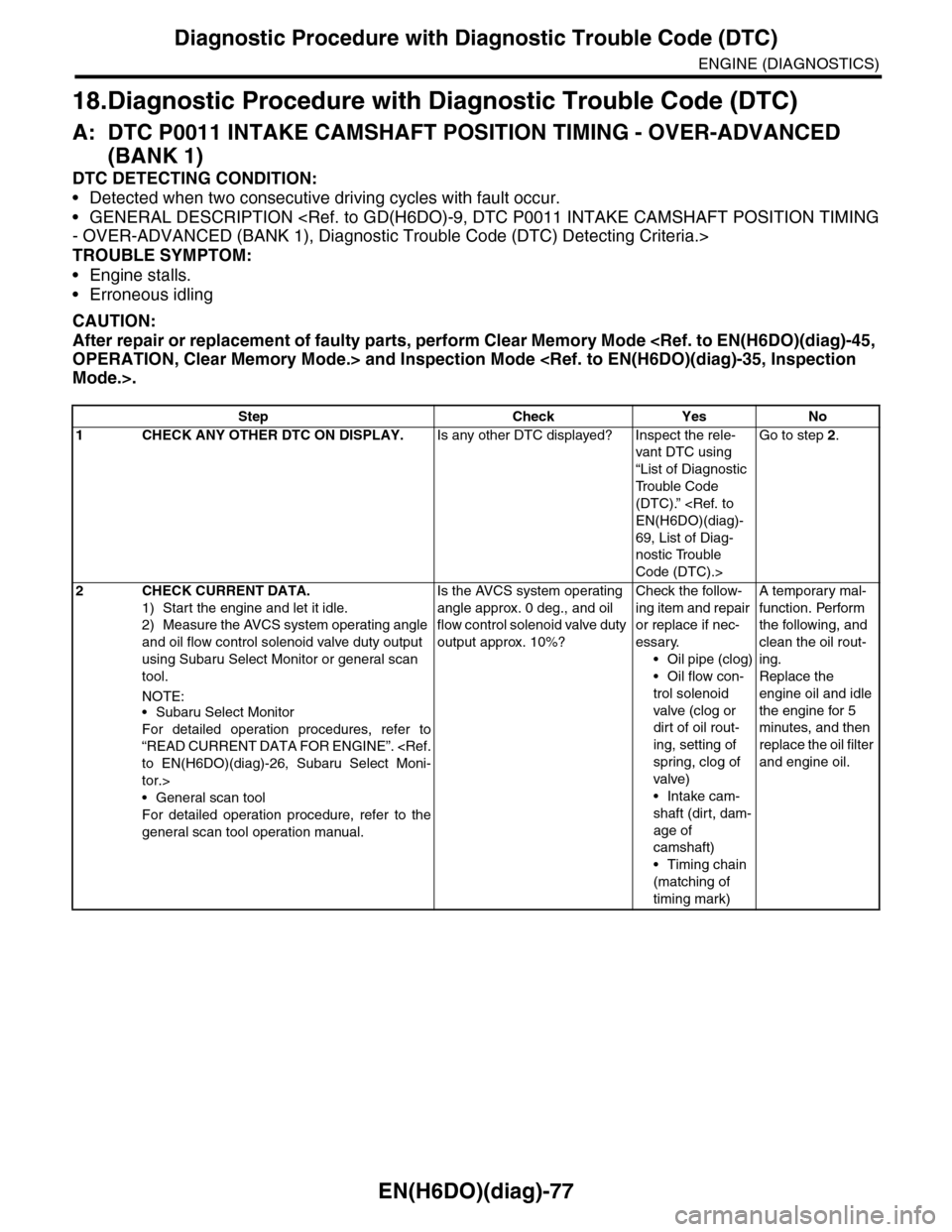
18.Diagnostic Procedure with Diagnostic Trouble Code (DTC)
A: DTC P0011 INTAKE CAMSHAFT POSITION TIMING - OVER-ADVANCED
(BANK 1)
DTC DETECTING CONDITION:
•Detected when two consecutive driving cycles with fault occur.
•GENERAL DESCRIPTION
TROUBLE SYMPTOM:
•Engine stalls.
•Erroneous idling
CAUTION:
After repair or replacement of faulty parts, perform Clear Memory Mode
Step Check Yes No
1CHECK ANY OTHER DTC ON DISPLAY.Is any other DTC displayed? Inspect the rele-
vant DTC using
“List of Diagnostic
Tr o u b l e C o d e
(DTC).”
69, List of Diag-
nostic Trouble
Code (DTC).>
Go to step 2.
2CHECK CURRENT DATA.
1) Start the engine and let it idle.
2) Measure the AVCS system operating angle
and oil flow control solenoid valve duty output
using Subaru Select Monitor or general scan
tool.
NOTE:•Subaru Select Monitor
For detailed operation procedures, refer to
“READ CURRENT DATA FOR ENGINE”.
tor.>
•General scan tool
For detailed operation procedure, refer to the
general scan tool operation manual.
Is the AVCS system operating
angle approx. 0 deg., and oil
flow control solenoid valve duty
output approx. 10%?
Check the follow-
ing item and repair
or replace if nec-
essary.
•Oil pipe (clog)
•Oil flow con-
trol solenoid
valve (clog or
dirt of oil rout-
ing, setting of
spring, clog of
valve)
•Intake cam-
shaft (dirt, dam-
age of
camshaft)
•Timing chain
(matching of
timing mark)
A temporary mal-
function. Perform
the following, and
clean the oil rout-
ing.
Replace the
engine oil and idle
the engine for 5
minutes, and then
replace the oil filter
and engine oil.
Page 1239 of 2453
EN(H6DO)(diag)-78
Diagnostic Procedure with Diagnostic Trouble Code (DTC)
ENGINE (DIAGNOSTICS)
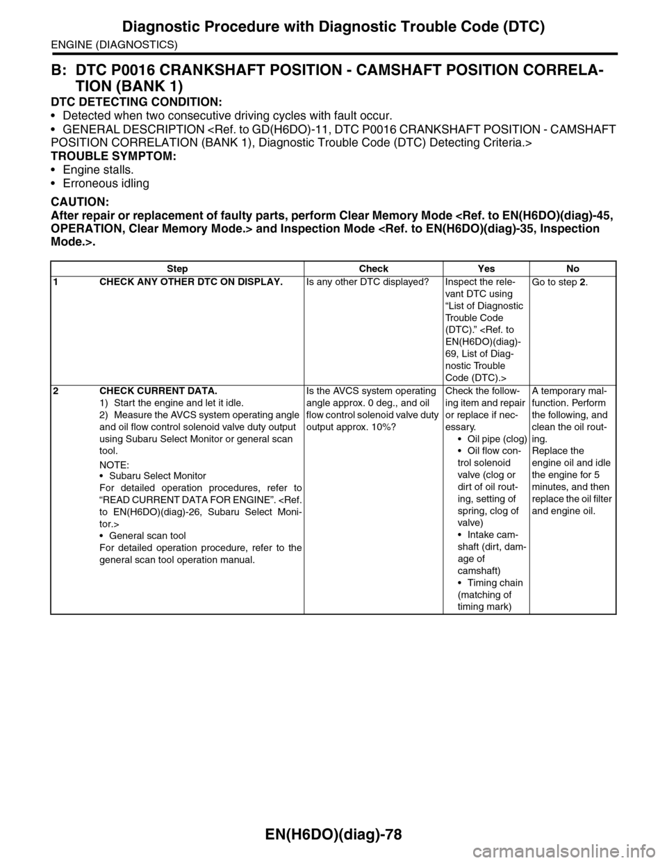
B: DTC P0016 CRANKSHAFT POSITION - CAMSHAFT POSITION CORRELA-
TION (BANK 1)
DTC DETECTING CONDITION:
•Detected when two consecutive driving cycles with fault occur.
•GENERAL DESCRIPTION
TROUBLE SYMPTOM:
•Engine stalls.
•Erroneous idling
CAUTION:
After repair or replacement of faulty parts, perform Clear Memory Mode
Step Check Yes No
1CHECK ANY OTHER DTC ON DISPLAY.Is any other DTC displayed? Inspect the rele-
vant DTC using
“List of Diagnostic
Tr o u b l e C o d e
(DTC).”
69, List of Diag-
nostic Trouble
Code (DTC).>
Go to step 2.
2CHECK CURRENT DATA.
1) Start the engine and let it idle.
2) Measure the AVCS system operating angle
and oil flow control solenoid valve duty output
using Subaru Select Monitor or general scan
tool.
NOTE:•Subaru Select Monitor
For detailed operation procedures, refer to
“READ CURRENT DATA FOR ENGINE”.
tor.>
•General scan tool
For detailed operation procedure, refer to the
general scan tool operation manual.
Is the AVCS system operating
angle approx. 0 deg., and oil
flow control solenoid valve duty
output approx. 10%?
Check the follow-
ing item and repair
or replace if nec-
essary.
•Oil pipe (clog)
•Oil flow con-
trol solenoid
valve (clog or
dirt of oil rout-
ing, setting of
spring, clog of
valve)
•Intake cam-
shaft (dirt, dam-
age of
camshaft)
•Timing chain
(matching of
timing mark)
A temporary mal-
function. Perform
the following, and
clean the oil rout-
ing.
Replace the
engine oil and idle
the engine for 5
minutes, and then
replace the oil filter
and engine oil.
Page 1240 of 2453
EN(H6DO)(diag)-79
Diagnostic Procedure with Diagnostic Trouble Code (DTC)
ENGINE (DIAGNOSTICS)
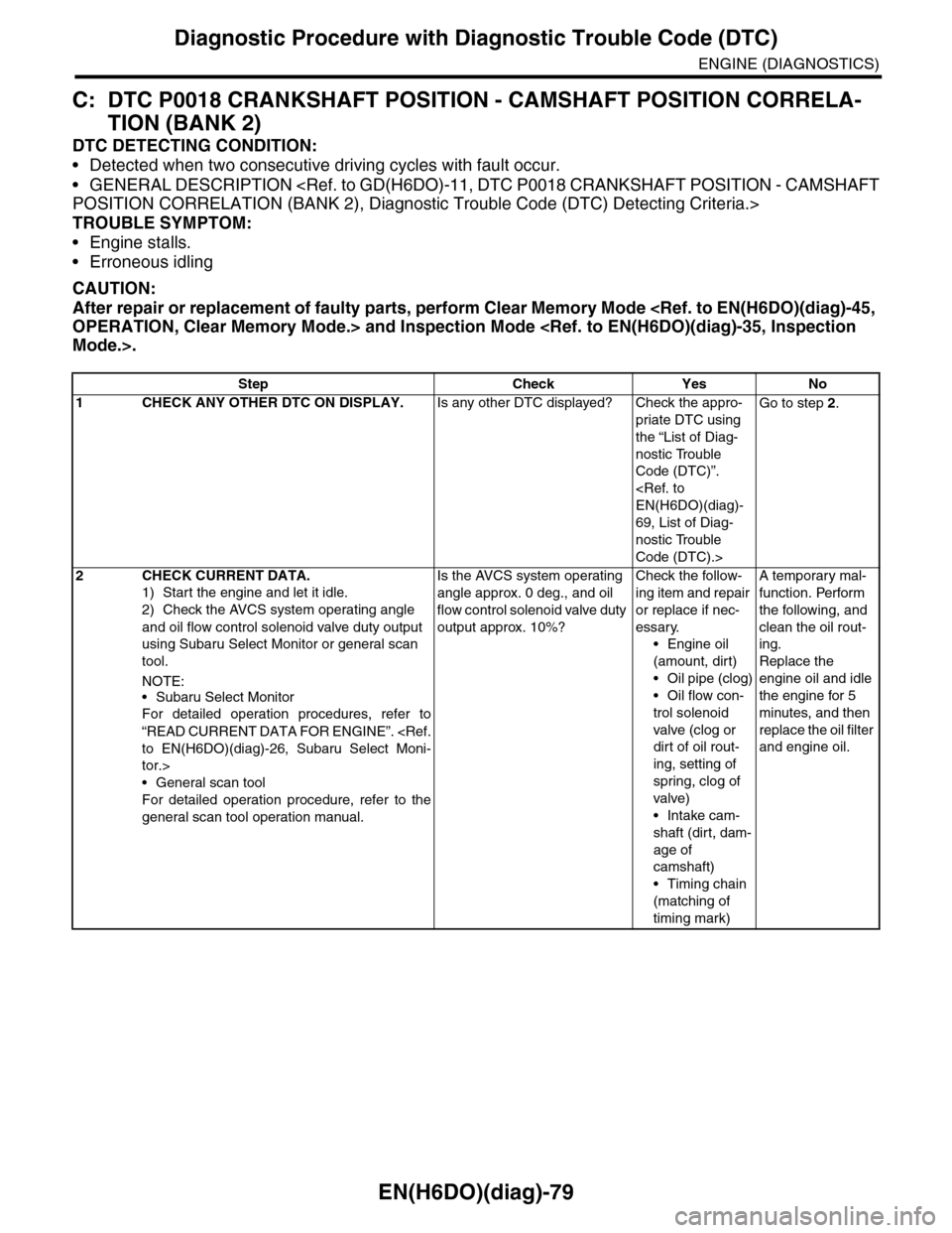
C: DTC P0018 CRANKSHAFT POSITION - CAMSHAFT POSITION CORRELA-
TION (BANK 2)
DTC DETECTING CONDITION:
•Detected when two consecutive driving cycles with fault occur.
•GENERAL DESCRIPTION
TROUBLE SYMPTOM:
•Engine stalls.
•Erroneous idling
CAUTION:
After repair or replacement of faulty parts, perform Clear Memory Mode
Step Check Yes No
1CHECK ANY OTHER DTC ON DISPLAY.Is any other DTC displayed? Check the appro-
priate DTC using
the “List of Diag-
nostic Trouble
Code (DTC)”.
69, List of Diag-
nostic Trouble
Code (DTC).>
Go to step 2.
2CHECK CURRENT DATA.
1) Start the engine and let it idle.
2) Check the AVCS system operating angle
and oil flow control solenoid valve duty output
using Subaru Select Monitor or general scan
tool.
NOTE:
•Subaru Select Monitor
For detailed operation procedures, refer to
“READ CURRENT DATA FOR ENGINE”.
tor.>
•General scan tool
For detailed operation procedure, refer to the
general scan tool operation manual.
Is the AVCS system operating
angle approx. 0 deg., and oil
flow control solenoid valve duty
output approx. 10%?
Check the follow-
ing item and repair
or replace if nec-
essary.
•Engine oil
(amount, dirt)
•Oil pipe (clog)
•Oil flow con-
trol solenoid
valve (clog or
dirt of oil rout-
ing, setting of
spring, clog of
valve)
•Intake cam-
shaft (dirt, dam-
age of
camshaft)
•Timing chain
(matching of
timing mark)
A temporary mal-
function. Perform
the following, and
clean the oil rout-
ing.
Replace the
engine oil and idle
the engine for 5
minutes, and then
replace the oil filter
and engine oil.
Page 1241 of 2453
EN(H6DO)(diag)-80
Diagnostic Procedure with Diagnostic Trouble Code (DTC)
ENGINE (DIAGNOSTICS)
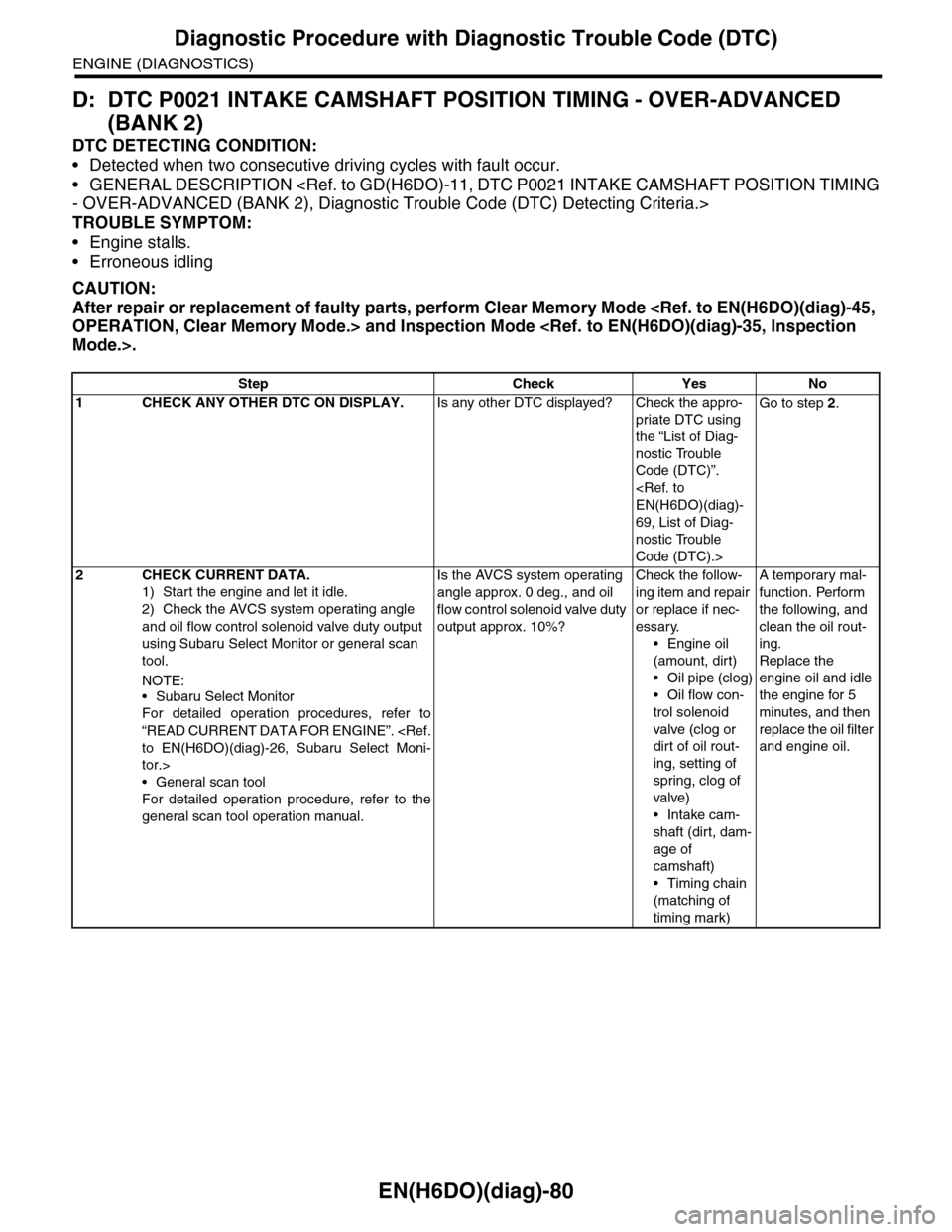
D: DTC P0021 INTAKE CAMSHAFT POSITION TIMING - OVER-ADVANCED
(BANK 2)
DTC DETECTING CONDITION:
•Detected when two consecutive driving cycles with fault occur.
•GENERAL DESCRIPTION
TROUBLE SYMPTOM:
•Engine stalls.
•Erroneous idling
CAUTION:
After repair or replacement of faulty parts, perform Clear Memory Mode
Step Check Yes No
1CHECK ANY OTHER DTC ON DISPLAY.Is any other DTC displayed? Check the appro-
priate DTC using
the “List of Diag-
nostic Trouble
Code (DTC)”.
69, List of Diag-
nostic Trouble
Code (DTC).>
Go to step 2.
2CHECK CURRENT DATA.
1) Start the engine and let it idle.
2) Check the AVCS system operating angle
and oil flow control solenoid valve duty output
using Subaru Select Monitor or general scan
tool.
NOTE:
•Subaru Select Monitor
For detailed operation procedures, refer to
“READ CURRENT DATA FOR ENGINE”.
tor.>
•General scan tool
For detailed operation procedure, refer to the
general scan tool operation manual.
Is the AVCS system operating
angle approx. 0 deg., and oil
flow control solenoid valve duty
output approx. 10%?
Check the follow-
ing item and repair
or replace if nec-
essary.
•Engine oil
(amount, dirt)
•Oil pipe (clog)
•Oil flow con-
trol solenoid
valve (clog or
dirt of oil rout-
ing, setting of
spring, clog of
valve)
•Intake cam-
shaft (dirt, dam-
age of
camshaft)
•Timing chain
(matching of
timing mark)
A temporary mal-
function. Perform
the following, and
clean the oil rout-
ing.
Replace the
engine oil and idle
the engine for 5
minutes, and then
replace the oil filter
and engine oil.
Page 1851 of 2453
LU(H6DO)-2
General Description
LUBRICATION
1. General Description
A: SPECIFICATION
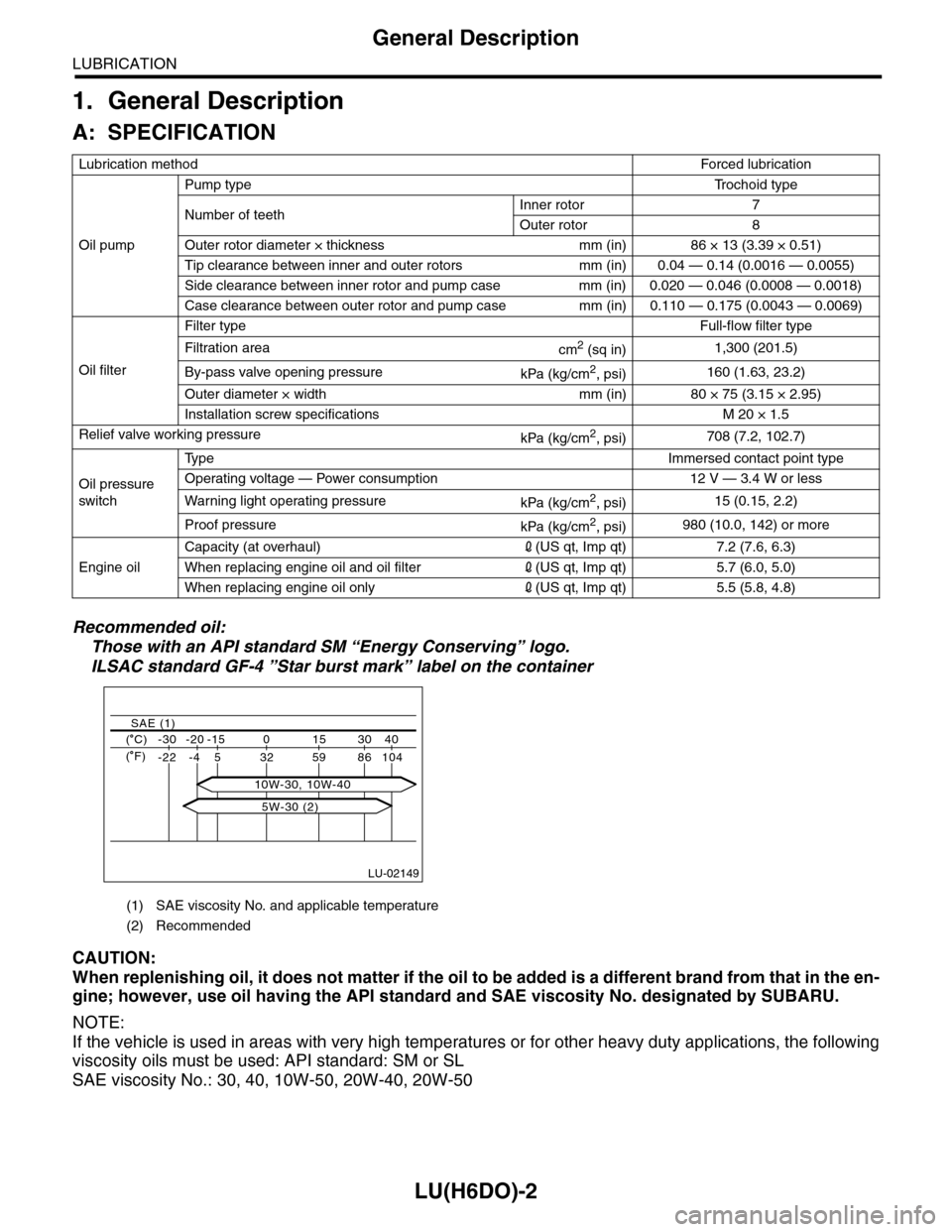
Recommended oil:
Those with an API standard SM “Energy Conserving” logo.
ILSAC standard GF-4 ”Star burst mark” label on the container
CAUTION:
When replenishing oil, it does not matter if the oil to be added is a different brand from that in the en-
gine; however, use oil having the API standard and SAE viscosity No. designated by SUBARU.
NOTE:
If the vehicle is used in areas with very high temperatures or for other heavy duty applications, the following
viscosity oils must be used: API standard: SM or SL
SAE viscosity No.: 30, 40, 10W-50, 20W-40, 20W-50
Lubrication methodForced lubr ication
Oil pump
Pump typeTr o c h o i d t y p e
Number of teethInner rotor 7
Outer rotor 8
Outer rotor diameter × thickness mm (in) 86 × 13 (3.39 × 0.51)
Tip clearance between inner and outer rotors mm (in) 0.04 — 0.14 (0.0016 — 0.0055)
Side clearance between inner rotor and pump case mm (in) 0.020 — 0.046 (0.0008 — 0.0018)
Case clearance between outer rotor and pump case mm (in) 0.110 — 0.175 (0.0043 — 0.0069)
Oil filter
Filter typeFull-flow filter type
Filtration areacm2 (sq in)1,300 (201.5)
By-pass valve opening pressurekPa (kg/cm2, psi)160 (1.63, 23.2)
Outer diameter × width mm (in) 80 × 75 (3.15 × 2.95)
Installation screw specifications M 20 × 1.5
Relief valve working pressurekPa (kg/cm2, psi)708 (7.2, 102.7)
Oil pressure
switch
Ty p eImmersed contact point type
Operating voltage — Power consumption 12 V — 3.4 W or less
Wa r ni n g l ig h t o p era t i ng pr e ss ur ekPa (kg/cm2, psi)15 (0.15, 2.2)
Proof pressurekPa (kg/cm2, psi)980 (10.0, 142) or more
Engine oil
Capacity (at overhaul)2(US qt, Imp qt) 7.2 (7.6, 6.3)
When replacing engine oil and oil filter2(US qt, Imp qt) 5.7 (6.0, 5.0)
When replacing engine oil only2(US qt, Imp qt) 5.5 (5.8, 4.8)
(1) SAE viscosity No. and applicable temperature
(2) Recommended
LU-02149
( C) -30 -20 -15 0 15 30 40
-22 -4 5 32 59 86 104
SAE (1)
( F)
5W-30 (2)
10W-30, 10W-40
Page 1853 of 2453
LU(H6DO)-4
General Description
LUBRICATION
C: CAUTION
•Wear work clothing, including a cap, protective goggles and protective shoes during operation.
•Remove contamination including dirt and corrosion before removal, installation or disassembly.
•Keep the disassembled parts in order and protect them from dust and dirt.
•Before removal, installation or disassembly, be sure to clarify the failure. Avoid unnecessary removal, in-
stallation, disassembly and replacement.
•Be careful not to burn yourself, because each part on the vehicle is hot after running.
•Be sure to tighten fasteners including bolts and nuts to the specified torque.
•Place shop jacks or rigid racks at the specified points.
•Before disconnecting connectors of sensors or units, be sure to disconnect the ground cable from battery.
D: PREPARATION TOOL
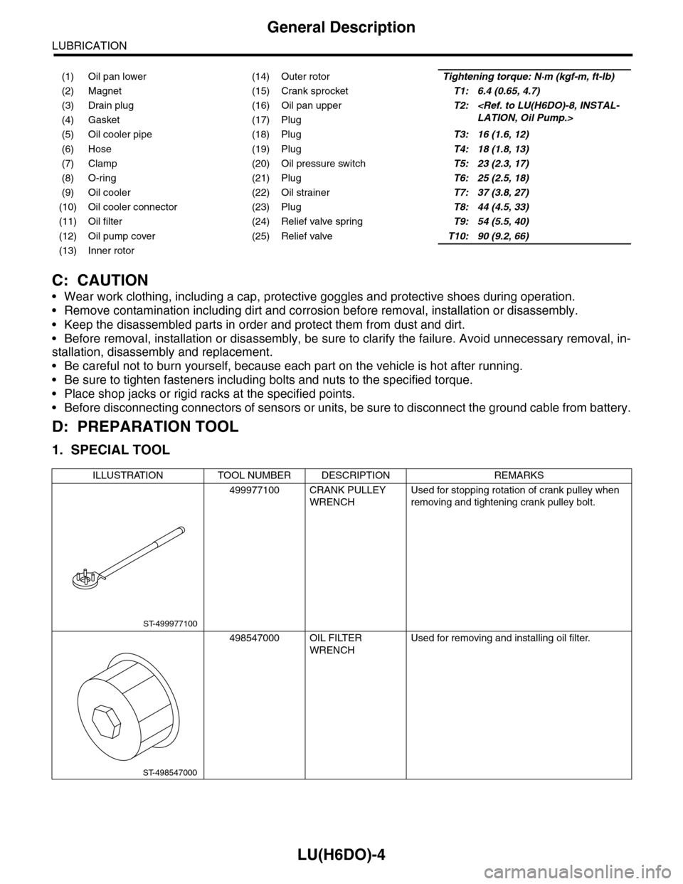
1. SPECIAL TOOL
(1) Oil pan lower (14) Outer rotorTightening torque: N·m (kgf-m, ft-lb)
(2) Magnet (15) Crank sprocketT1: 6.4 (0.65, 4.7)
(3) Drain plug (16) Oil pan upperT2:
(5) Oil cooler pipe (18) PlugT3: 16 (1.6, 12)
(6) Hose (19) PlugT4: 18 (1.8, 13)
(7) Clamp (20) Oil pressure switchT5: 23 (2.3, 17)
(8) O-ring (21) PlugT6: 25 (2.5, 18)
(9) Oil cooler (22) Oil strainerT7: 37 (3.8, 27)
(10) Oil cooler connector (23) PlugT8: 44 (4.5, 33)
(11) Oil filter (24) Relief valve springT9: 54 (5.5, 40)
(12) Oil pump cover (25) Relief valveT10: 90 (9.2, 66)
(13) Inner rotor
ILLUSTRATION TOOL NUMBER DESCRIPTION REMARKS
499977100 CRANK PULLEY
WRENCH
Used for stopping rotation of crank pulley when
removing and tightening crank pulley bolt.
498547000 OIL FILTER
WRENCH
Used for removing and installing oil filter.
ST-499977100
ST-498547000
Page 1863 of 2453
LU(H6DO)-14
Engine Oil Filter
LUBRICATION
8. Engine Oil Filter
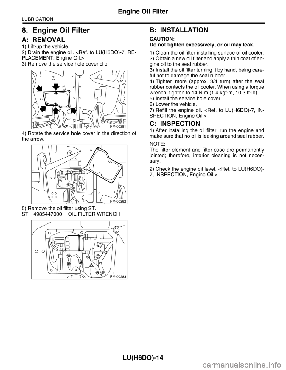
A: REMOVAL
1) Lift-up the vehicle.
2) Drain the engine oil.
3) Remove the service hole cover clip.
4) Rotate the service hole cover in the direction of
the arrow.
5) Remove the oil filter using ST.
ST 4985447000 OIL FILTER WRENCH
B: INSTALLATION
CAUTION:
Do not tighten excessively, or oil may leak.
1) Clean the oil filter installing surface of oil cooler.
2) Obtain a new oil filter and apply a thin coat of en-
gine oil to the seal rubber.
3) Install the oil filter turning it by hand, being care-
ful not to damage the seal rubber.
4) Tighten more (approx. 3/4 turn) after the seal
rubber contacts the oil cooler. When using a torque
wrench, tighten to 14 N·m (1.4 kgf-m, 10.3 ft-lb).
5) Install the service hole cover.
6) Lower the vehicle.
7) Refill the engine oil.
C: INSPECTION
1) After installing the oil filter, run the engine and
make sure that no oil is leaking around seal rubber.
NOTE:
The filter element and filter case are permanently
jointed; therefore, interior cleaning is not neces-
sary.
2) Check the engine oil level.
PM-00281
PM-00282
PM-00283
Page 1864 of 2453
LU(H6DO)-15
Oil Cooler
LUBRICATION
9. Oil Cooler
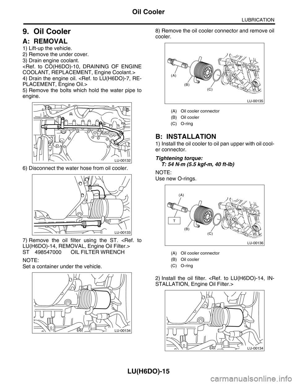
A: REMOVAL
1) Lift-up the vehicle.
2) Remove the under cover.
3) Drain engine coolant.
4) Drain the engine oil.
5) Remove the bolts which hold the water pipe to
engine.
6) Disconnect the water hose from oil cooler.
7) Remove the oil filter using the ST.
ST 498547000 OIL FILTER WRENCH
NOTE:
Set a container under the vehicle.
8) Remove the oil cooler connector and remove oil
cooler.
B: INSTALLATION
1) Install the oil cooler to oil pan upper with oil cool-
er connector.
Tightening torque:
T: 54 N·m (5.5 kgf-m, 40 ft-lb)
NOTE:
Use new O-rings.
2) Install the oil filter.
LU-00132
LU-00133
LU-00134
(A) Oil cooler connector
(B) Oil cooler
(C) O-ring
(A) Oil cooler connector
(B) Oil cooler
(C) O-ring
(A)
(B)(C)
LU-00135
(A)
(B)(C)
T
LU-00136
LU-00134