Page 1865 of 2453
LU(H6DO)-16
Oil Cooler
LUBRICATION
3) Connect the water hose.
4) Install the water pipe onto engine.
Tightening torque:
6.4 N·m (0.65 kgf-m, 4.7 ft-lb)
5) Refill the engine oil.
PLACEMENT, Engine Oil.>
6) Fill engine coolant.
FILLING OF ENGINE COOLANT, REPLACE-
MENT, Engine Coolant.>
7) Check the engine oil level.
7, INSPECTION, Engine Oil.>
C: INSPECTION
1) Check that coolant passages are not clogged
using an compressed air.
2) Check that the oil pan upper and O-ring installing
surface of oil filter are not damaged.
LU-00133
LU-00132
Page 1866 of 2453

LU(H6DO)-17
General Diagnostics Table
LUBRICATION
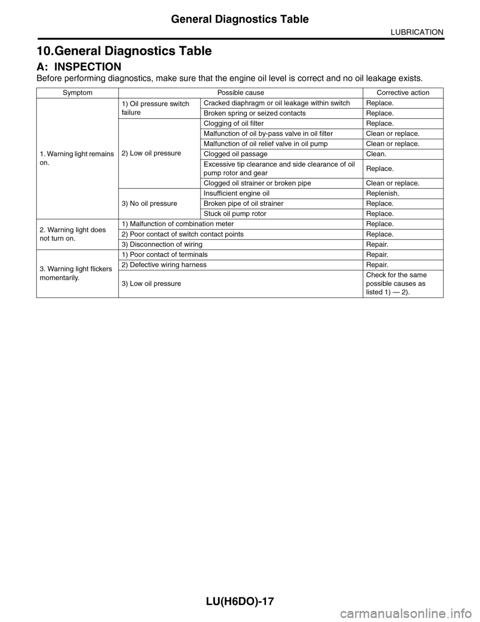
10.General Diagnostics Table
A: INSPECTION
Before performing diagnostics, make sure that the engine oil level is correct and no oil leakage exists.
Symptom Possible cause Corrective action
1. Warning light remains
on.
1) Oil pressure switch
failure
Cracked diaphragm or oil leakage within switch Replace.
Broken spring or seized contacts Replace.
2) Low oil pressure
Clogging of oil filter Replace.
Malfunction of oil by-pass valve in oil filter Clean or replace.
Malfunction of oil relief valve in oil pump Clean or replace.
Clogged oil passage Clean.
Excessive tip clearance and side clearance of oil
pump rotor and gearReplace.
Clogged oil strainer or broken pipe Clean or replace.
3) No oil pressure
Insufficient engine oil Replenish.
Broken pipe of oil strainer Replace.
Stuck oil pump rotor Replace.
2. Warning light does
not turn on.
1) Malfunction of combination meter Replace.
2) Poor contact of switch contact points Replace.
3) Disconnection of wiring Repair.
3. Warning light flickers
momentarily.
1) Poor contact of terminals Repair.
2) Defective wiring harness Repair.
3) Low oil pressure
Check for the same
possible causes as
listed 1) — 2).
Page 1878 of 2453
ME(H6DO)-12
General Description
MECHANICAL
(1) Cylinder block (RH) (13) ClampTightening torque: N·m (kgf-m, ft-lb)
(2) Cylinder block (LH) (14) HoseT1: 6.4 (0.65, 4.7)
(3) Rear oil seal (15) Oil cooler pipeT2: 18 (1.8, 13.3)
(4) Service hole cover (16) Oil coolerT3: 25 (2.5, 18)
(5) O-ring (17) ConnectorT4: 16 (1.6, 12)
(6) Oil pan upper (18) Oil filterT5: 37 (3.8, 27)
(7) Oil pressure switch (19) PlugT6: 44 (4.5, 33)
(8) Oil strainer (20) Crankshaft position sensor holderT7: 54 (5.5, 40)
(9) Magnet (21) Relief valveT8: 70 (7.1, 52)
(10) Oil pan lower (22) Relief valve springT9: 23 (2.3, 17)
(11) Metal gasket (23) PlugT10: 90 (9.2, 67)
(12) Drain plug
Page 1884 of 2453
ME(H6DO)-18
General Description
MECHANICAL
499765700 VALVE GUIDE
REMOVER
Used for removing valve guides.
499765900 VALVE GUIDE
REAMER
Used for reaming valve guides.
499977100 CRANK PULLEY
WRENCH
Used for stopping rotation of crank pulley when
loosening/tightening crank pulley bolt.
18252AA000 CRANKSHAFT
SOCKET
Used for rotating crankshaft.
498547000 OIL FILTER
WRENCH
Used for removing and installing oil filter.
ILLUSTRATION TOOL NUMBER DESCRIPTION REMARKS
ST-499765700
ST-499765900
ST-499977100
ST18252AA000
ST-498547000
Page 1891 of 2453
ME(H6DO)-25
Engine Oil Pressure
MECHANICAL
6. Engine Oil Pressure
A: INSPECTION
1) Remove the oil pressure switch from cylinder
block.
Pressure Switch.>
2) Connect the oil pressure gauge hose to cylinder
block.
3) Connect the ground cable to the battery.
4) Start the engine, and measure the oil pressure.
OIL PRESSURE (at oil temperature of 80°C
(176°F)):
Standard:
135 kPa (1.4 kgf/cm2, 20 psi) or more (at
600 rpm)
500 kPa (5.1 kgf/cm2, 73 psi) or more (at
5,000 rpm)
CAUTION:
•If the oil pressure is out of specification,
check oil pump, oil filter and lubrication line.
Diagnostics Table.>
•If the oil pressure warning light is turned ON
and oil pressure is in specification, replace the
oil pressure switch.
SPECTION, General Diagnostics Table.>
5) After measuring the oil pressure, install the oil
pressure switch.
LATION, Oil Pressure Switch.>
Tightening torque:
25 N·m (2.5 kgf-m, 18 ft-lb)
Page 1906 of 2453

ME(H6DO)-40
Preparation for Overhaul
MECHANICAL
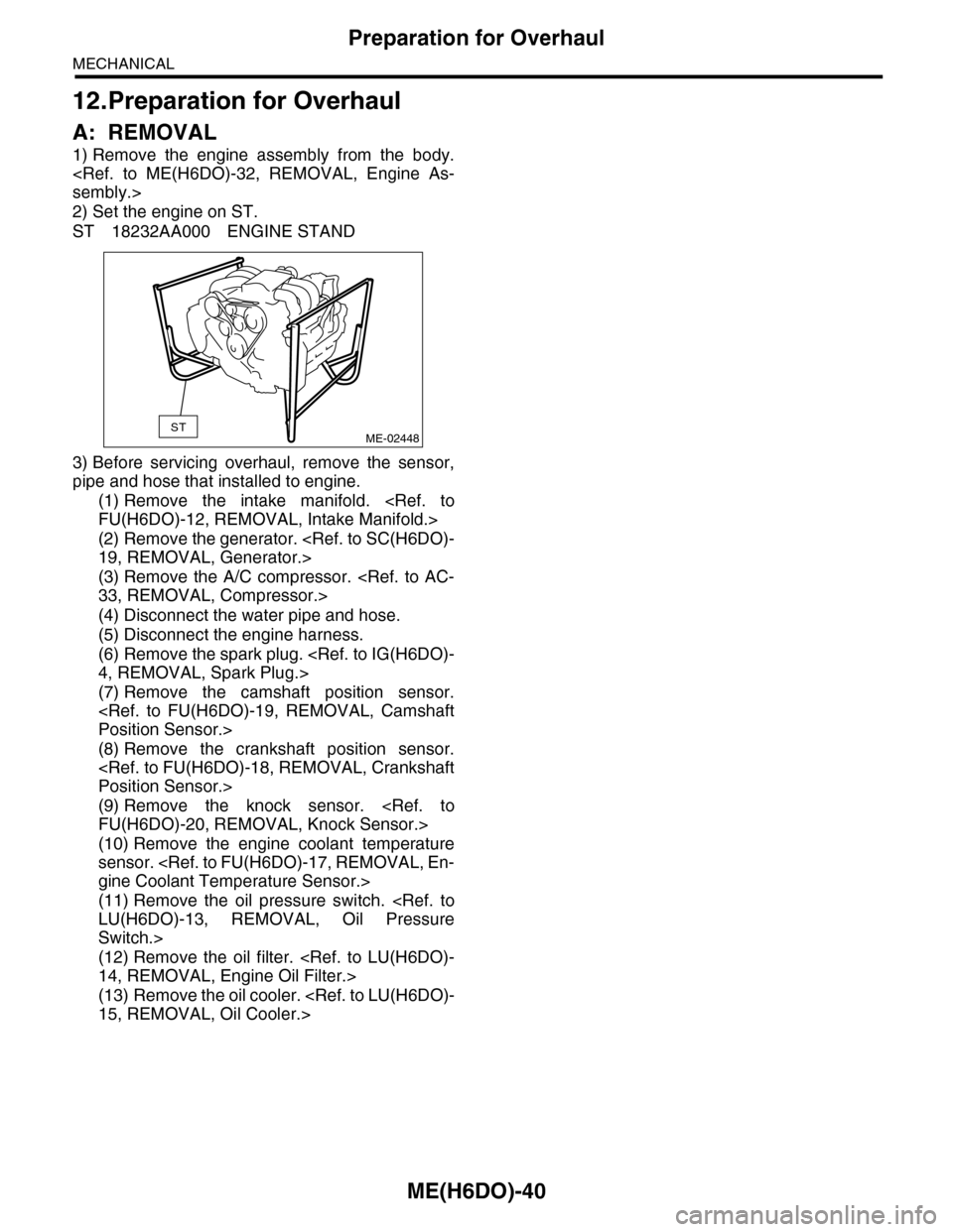
12.Preparation for Overhaul
A: REMOVAL
1) Remove the engine assembly from the body.
sembly.>
2) Set the engine on ST.
ST 18232AA000 ENGINE STAND
3) Before servicing overhaul, remove the sensor,
pipe and hose that installed to engine.
(1) Remove the intake manifold.
FU(H6DO)-12, REMOVAL, Intake Manifold.>
(2) Remove the generator.
19, REMOVAL, Generator.>
(3) Remove the A/C compressor.
33, REMOVAL, Compressor.>
(4) Disconnect the water pipe and hose.
(5) Disconnect the engine harness.
(6) Remove the spark plug.
4, REMOVAL, Spark Plug.>
(7) Remove the camshaft position sensor.
Position Sensor.>
(8) Remove the crankshaft position sensor.
Position Sensor.>
(9) Remove the knock sensor.
FU(H6DO)-20, REMOVAL, Knock Sensor.>
(10) Remove the engine coolant temperature
sensor.
gine Coolant Temperature Sensor.>
(11) Remove the oil pressure switch.
LU(H6DO)-13, REMOVAL, Oil Pressure
Switch.>
(12) Remove the oil filter.
14, REMOVAL, Engine Oil Filter.>
(13) Remove the oil cooler.
15, REMOVAL, Oil Cooler.>
STME-02448
Page 1919 of 2453
ME(H6DO)-53
Camshaft
MECHANICAL
19.Camshaft
A: REMOVAL
1) Remove the crank pulley.
41, REMOVAL, Crank Pulley.>
2) Remove the front chain cover.
ME(H6DO)-42, REMOVAL, Front Chain Cover.>
3) Remove the timing chain assembly.
Assembly.>
4) Remove the cam sprocket.
et.>
5) Remove the crank sprocket.
et.>
6) Remove the rear chain cover.
Cover.>
7) Disconnect the oil pipe.
8) Remove the rocker cover (LH).
9) Remove the plugs (LH).
10) Loosen the camshaft cap bolts equally, a little
at a time in alphabetical sequence shown in the fig-
ure.
11) Remove the camshaft caps and camshaft (LH).
NOTE:
Arrange camshaft caps in order so that they can be
installed in their original positions.
12) Similarly, remove the camshafts (RH) and re-
lated parts.(A) Bolt without filter (with white mark)
(B) Bolt with filter (without white mark)
ME-02513
(A)
(B)
ME-02055
ME-02054(1)
(2)
(8)
(7)(9)
(3)
(4)
(5)
(6)(10)
(11)(13)
(14)(12)
(15)
(16)
Page 1921 of 2453

ME(H6DO)-55
Camshaft
MECHANICAL
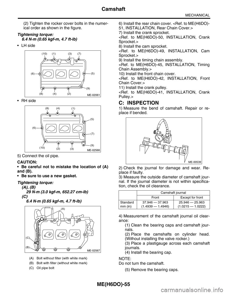
(2) Tighten the rocker cover bolts in the numer-
ical order as shown in the figure.
Tightening torque:
6.4 N·m (0.65 kgf-m, 4.7 ft-lb)
•LH side
•RH side
5) Connect the oil pipe.
CAUTION:
•Be careful not to mistake the location of (A)
and (B).
•Be sure to use a new gasket.
Tightening torque:
(A), (B)
29 N·m (3.0 kgf-m, 652.27 cm-lb)
(C)
6.4 N·m (0.65 kgf-m, 4.7 ft-lb)
6) Install the rear chain cover.
51, INSTALLATION, Rear Chain Cover.>
7) Install the crank sprocket.
Sprocket.>
8) Install the cam sprocket.
Sprocket.>
9) Install the timing chain assembly.
Chain Assembly.>
10) Install the front chain cover.
Chain Cover.>
11) Install the crank pulley.
Pulley.>
C: INSPECTION
1) Measure the bend of camshaft. Repair or re-
place if bended.
2) Check the journal for damage and wear. Re-
place if faulty.
3) Measure the outside diameter of camshaft jour-
nal. If the journal diameter is not within specifica-
tion, check the oil clearance.
4) Measurement of the camshaft journal oil clear-
ance:
(1) Clean the bearing caps and camshaft jour-
nals.
(2) Place the camshafts on cylinder head.
(Without installing the valve rocker.)
(3) Place a plastigauge across each camshaft
journals.
(4) Install the bearing cap.
NOTE:
Do not turn the camshaft.
(5) Remove the bearing caps.
(A) Bolt without filter (with white mark)
(B) Bolt with filter (without white mark)
(C) Oil pipe bolt
ME-02061(2)
(7)(3)(1)(10)
(6)
(8)(4)
(5)
(9)
ME-02566
(8)(4)(1)
(5)
(7)
(9)(3)(2)
(6)
(10)
ME-02567
(A)
(C)
(B)
Camshaft journal
Front Except for front
Standard
mm (in)
37.946 — 37.963
(1.4939 — 1.4946)
25.946 — 25.963
(1.0215 — 1.0222)
ME-00539