2009 SUBARU TRIBECA fuse box location
[x] Cancel search: fuse box locationPage 366 of 2453

AC-40
Relay and Fuse
HVAC SYSTEM (HEATER, VENTILATOR AND A/C)
19.Relay and Fuse
A: LOCATION
B: INSPECTION
While applying battery voltage to the terminal be-
tween (3) and (4), check continuity between (1) and
(2).
If no continuity exists, replace the relay with a new
one.
(1) Joint box
(2) Main fuse box
Main fan relay 1 (A)
Main fan relay 2 (B)
Sub fan relay (C)
A/C relay (D)
A/C Fuse (E)
AC-00787
(E)(1)
(2)
(A)
(B)(D)
(C)
(3) — (4): Continuity exists
(1) — (2): Continuity does not exist
AC-00641
1
1
2
2
3
3
4
4
Page 2295 of 2453
WI-11
Basic Diagnostic Procedure
WIRING SYSTEM
1. RELAY
A symbol used to indicate a relay.
2. CONNECTOR 1
The sketch of the connector indicates the one-pole
types.
3. WIRING CONNECTION
Some wiring diagrams are indicated in foldouts for
convenience. Wiring destinations are indicated
where necessary by corresponding symbols.
(When two pages are needed for clear indication)
4. FUSE NO. & RATING
The “FUSE No. & RATING“ corresponds with that
used in the fuse box (main fuse box, fuse and joint
box).
5. CONNECTOR 2
•Each connector is indicated by a symbol.
•Each terminal number is indicated in the corre-
sponding wiring diagram in an abbreviated form.
•For example, terminal number "G4" refers to No.
4 terminal of connector (G: F41) shown in the con-
nector sketch.
6. CONNECTOR SKETCH
•Each connector sketch clearly identifies the
shape and color of a connector as well as terminal
locations. Non-colored connectors are indicated in
white or natural color.
•When more than two types of connector number
are indicated in a connector sketch, it means that
the same type connectors are used.
7. GROUND
Each grounding point can be located easily by re-
ferring to the corresponding wiring harness.
8. DIODE
A symbol is used to indicate a diode.
9. WIRE TRACING ON EXTENDED WIRING
DIAGRAMS
For a wiring diagram extending over at least two
pages, a symbol (consisting of the same characters
with arrows), facilitates wire tracing from one page
to the next.
A ←→ B, B ←→ B
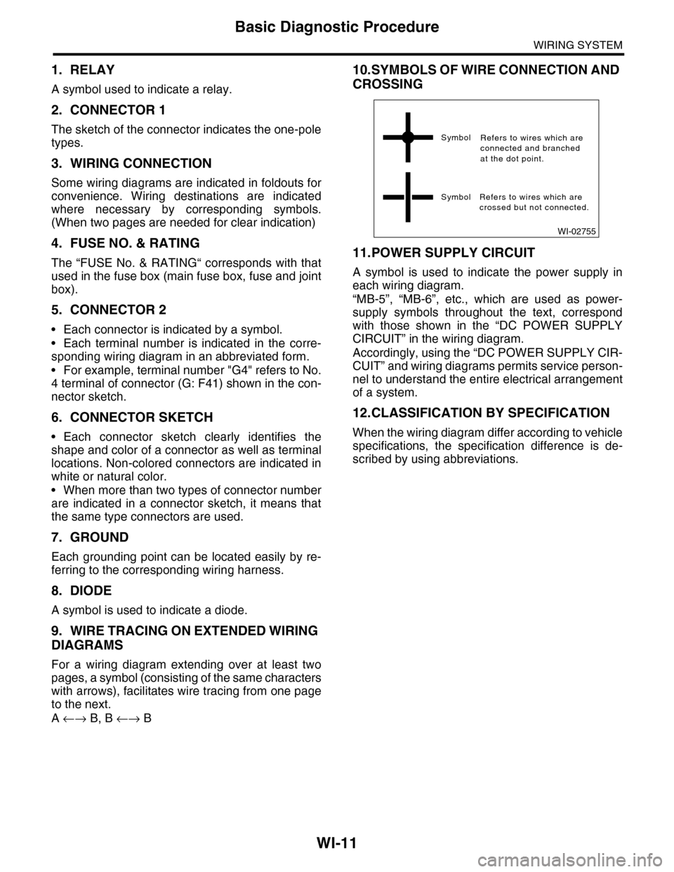
10.SYMBOLS OF WIRE CONNECTION AND
CROSSING
11.POWER SUPPLY CIRCUIT
A symbol is used to indicate the power supply in
each wiring diagram.
“MB-5”, “MB-6”, etc., which are used as power-
supply symbols throughout the text, correspond
with those shown in the “DC POWER SUPPLY
CIRCUIT” in the wiring diagram.
Accordingly, using the “DC POWER SUPPLY CIR-
CUIT” and wiring diagrams permits service person-
nel to understand the entire electrical arrangement
of a system.
12.CLASSIFICATION BY SPECIFICATION
When the wiring diagram differ according to vehicle
specifications, the specification difference is de-
scribed by using abbreviations.
WI-02755
Symbol
Symbol Refers to wires which arecrossed but not connected.
Refers to wires which areconnected and branchedat the dot point.
Page 2434 of 2453
WI-150
Front Wiring Harness
WIRING SYSTEM
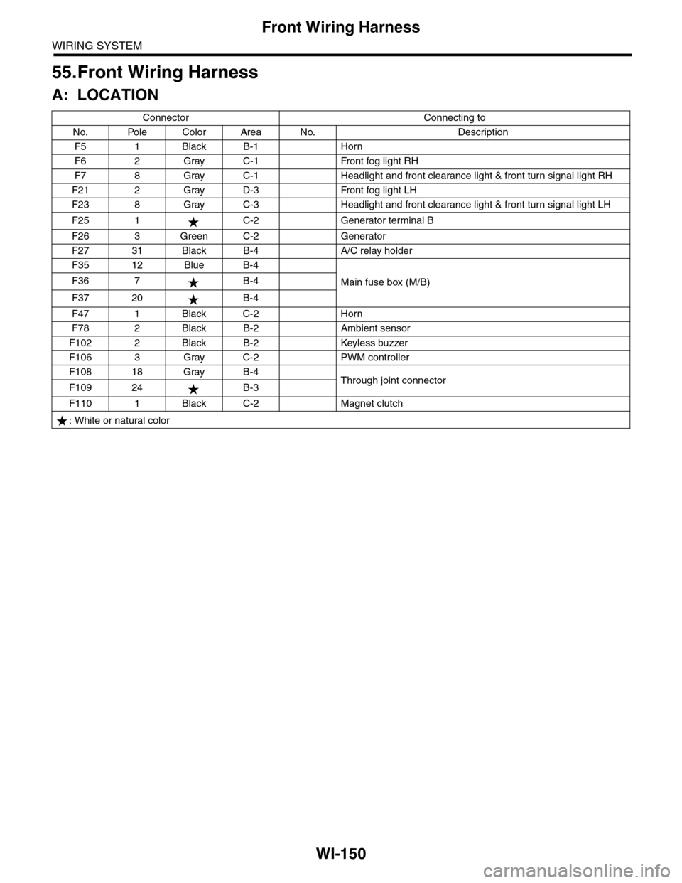
55.Front Wiring Harness
A: LOCATION
Connector Connecting to
No. Pole Color Area No. Description
F5 1 Black B-1 Horn
F6 2 Gray C-1 Front fog light RH
F7 8 Gray C-1 Headlight and front clearance light & front turn signal light RH
F21 2 Gray D-3 Front fog light LH
F23 8 Gray C-3 Headlight and front clearance light & front turn signal light LH
F25 1 C-2 Generator terminal B
F26 3 Green C-2 Generator
F27 31 Black B-4 A/C relay holder
F35 12 Blue B-4
Main fuse box (M/B)F36 7 B-4
F37 20 B-4
F47 1 Black C-2 Horn
F78 2 Black B-2 Ambient sensor
F102 2 Black B-2 Keyless buzzer
F106 3 Gray C-2 PWM controller
F108 18 Gray B-4Through joint connectorF109 24 B-3
F110 1 Black C-2 Magnet clutch
: White or natural color
Page 2436 of 2453
WI-152
Bulkhead Wiring Harness (In Engine Compartment)
WIRING SYSTEM
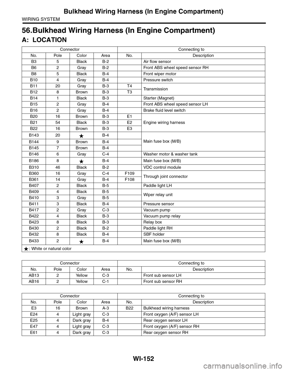
56.Bulkhead Wiring Harness (In Engine Compartment)
A: LOCATION
Connector Connecting to
No. Pole Color Area No. Description
B3 5 Black B-2 Air flow sensor
B6 2 Gray B-2 Front ABS wheel speed sensor RH
B8 5 Black B-4 Front wiper motor
B10 4 Gray B-4 Pressure switch
B11 20 Gray B-3 T4Tr a n s m i s s i o nB12 8 Brown B-3 T3
B14 1 Black B-3 Starter (Magnet)
B15 2 Gray B-4 Front ABS wheel speed sensor LH
B16 2 Gray B-4 Brake fluid level switch
B20 16 Brown B-3 E1
Engine wiring harnessB21 54 Black B-3 E2
B22 16 Brown B-3 E3
B143 20 B-4
Main fuse box (M/B)B144 9 Brown B-4
B145 7 Brown B-4
B146 6 Gray C-4 Washer motor & washer tank
B186 8 B-4 Main fuse box (M/B)
B310 46 Black B-2 VDC control module
B360 16 Gray C-4 F109Through joint connectorB361 14 Gray B-4 F108
B407 2 Black B-5 Paddle light LH
B409 4 Black B-5Wiper relay unitB410 3 Gray B-5
B411 3 Black B-4 Pressure sensor
B417 2 Gray C-3 Vacuum pump
B422 4 Black B-3 Vacuum pump relay
B423 8 Black B-3 Relay box
B430 2 Black B-2 Paddle light RH
B432 8 Black B-4 SBF holder
B433 2 B-4 Main fuse box (M/B)
: White or natural color
Connector Connecting to
No. Pole Color Area No. Description
AB13 2 Yellow C-3 Front sub sensor LH
AB16 2 Yellow C-1 Front sub sensor RH
Connector Connecting to
No. Pole Color Area No. Description
E3 16 Brown A-3 B22 Bulkhead wiring harness
E24 4 Light gray C-3 Front oxygen (A/F) sensor LH
E25 4 Dark gray B-4 Rear oxygen sensor LH
E47 4 Light gray C-3 Front oxygen (A/F) sensor RH
E61 4 Dark gray C-3 Rear oxygen sensor RH
Page 2438 of 2453
WI-154
Bulkhead Wiring Harness (In Compartment)
WIRING SYSTEM
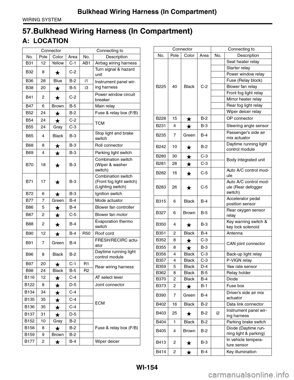
57.Bulkhead Wiring Harness (In Compartment)
A: LOCATION
Connector Connecting to
No. Pole Color Area No. Description
B31 12 Yellow C-1 AB1 Airbag wiring harness
B32 8 C-2Tu r n s i g n a l & h a z a r d
unit
B36 28 Blue B-2 i1Instrument panel wir-
ing harnessB38 20 B-5 i3
B41 2 C-2Powe r w in d ow ci r cu i t
breaker
B47 6 Brown B-5 Main relay
B52 24 B-2 Fuse & relay box (F/B)
B54 24 C-2TCMB55 24 Gray C-3
B65 4 Black B-3Stop light and brake
switch
B68 8 B-3 Roll connector
B69 4 B-3 Parking light switch
B70 18 B-3
Combination switch
(Wiper & washer
switch)
B71 17 B-3
Combination switch
(Front fog light switch)
(Lighting switch)
B72 6 B-3 Ignition switch
B77 7 Green B-4 Mode actuator
B86 5 B-4 Blower fan controller
B87 2 C-5 Blower fan motor
B88 2 B-4Evaporation thermo
switch
B90 12 B-4 R50 Roof cord
B91 7 Green B-4FRESH/RECIRC actu-
ator
B96 8 Black B-2Daytime running light
control module
B97 20 C-1 R1Rear wiring harnessB98 24 Black B-5 R2
B116 12 C-4 AT select lever
B122 8 D-5 Joint connector
B134 34 C-4
ECMB135 35 C-4
B136 35 C-4
B137 31 D-5
B152 10 Gray B-2
Fuse & relay box (F/B)B158 8 B-2
B159 9 Brown B-2
B177 2 B-4 Wiper deicer
B225 40 Black C-2
Seat heater relay
Starter relay
Pow er w i n dow r el ay
Fuse (Relay block)
Blower fan relay
Fr o nt fog li g ht r el ay
Mirror heater relay
Rear fog light relay
Wiper deicer relay
B228 15 B-2 OP connector
B231 4 B-3 Steering angle sensor
B235 7 Green B-4Passenger’s side air
mix actuator
B242 10 B-2Daytime running light
control module
B280 30 C-3Body integrated unitB281 28 C-3
B282 16 C-5Auto A/C control mod-
ule
B283 26 C-5
Auto A/C control mod-
ule (Rear defogger
switch)
B315 6 Black B-4Accelerator pedal
position sensor
B327 6 Brown B-5Rear oxygen sensor
relay
B350 4 B-3Key war ning switch &
key lock solenoid
B351 2 Black B-4 Antenna
B352 8 C-3CAN joint connectorB355 8 B-3
B356 4 Black C-3 Back-up light relay
B357 4 Black C-3 P-VIGN relay
B359 5 Black D-4 Yaw rate sensor
B362 8 Black B-5 Relay holder
B370 2 Black B-4 Diode
B373 2 B-1 Fuse box
B390 7 Green B-4Driver’s side air mix
actuator
B402 16 Black B-2 Data link connector
B403 25 B-2 i2Instrument panel wir-
ing harness
B404 1 Black B-2 Parking brake switch
B405 4 Brown B-2Diode (Daytime run-
ning light & parking)
B413 2 B-3In vehicle tempera-
ture sensor
B414 2 B-4 Key illumination
Connector Connecting to
No. Pole Color Area No. Description
Page 2443 of 2453
WI-159
Instrument Panel Wiring Harness
WIRING SYSTEM
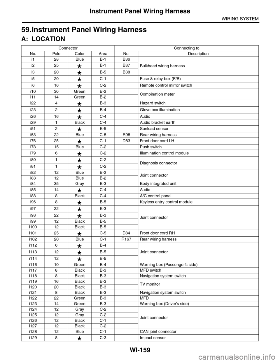
59.Instrument Panel Wiring Harness
A: LOCATION
Connector Connecting to
No. Pole Color Area No. Description
i1 28 Blue B-1 B36
Bulkhead wiring harnessi2 25 B-1 B37
i3 20 B-5 B38
i5 20 C-1 Fuse & relay box (F/B)
i6 16 C-2 Remote control mirror switch
i10 30 Green B-2Combination meteri11 14 Green B-2
i22 4 B-3 Hazard switch
i23 2 B-4 Glove box illumination
i26 16 C-4 Audio
i29 1 Black C-4 Audio bracket earth
i51 2 B-5 Sunload sensor
i53 22 Blue C-5 R98 Rear wiring harness
i76 25 C-1 D83 Front door cord LH
i78 15 Blue C-2 Push switch
i79 6 C-2 Illumination control module
i80 1 C-2Diagnosis connectori81 1 C-2
i82 12 Blue B-2Joint connectori83 12 Blue B-2
i84 35 Gray B-3 Body integrated unit
i85 14 C-4 Audio
i88 8 Black C-4 A/C control panel
i96 8 B-5 Keyless entry control module
i97 22 B-3
Joint connectori98 22 B-3
i99 12 Black B-5
i100 12 Black B-5
i101 25 C-5 D84 Front door cord RH
i102 20 Blue C-1 R167 Rear wiring harness
i112 6 B-4
Joint connectori113 12 B-5
i114 12 B-5
i116 10 Green B-4 Warning box (Passenger’s side)
i117 8 Black B-3 MFD switch
i118 8 Black B-3 Navigation system switch
i119 16 Black B-3TV monitori120 20 Black B-3
i121 8 Black B-3 Navigation system switch
i122 22 Green B-3 MFD
i123 14 Green B-3 Warning box (Driver’s side)
i124 12 Gray C-2
Joint connectori125 12 Gray C-2
i126 12 Black C-1
i127 12 Black C-2
i128 12 Blue C-1 CAN joint connector
i129 8 C-3 Impact sensor