Page 1242 of 2453
EN(H6DO)(diag)-81
Diagnostic Procedure with Diagnostic Trouble Code (DTC)
ENGINE (DIAGNOSTICS)
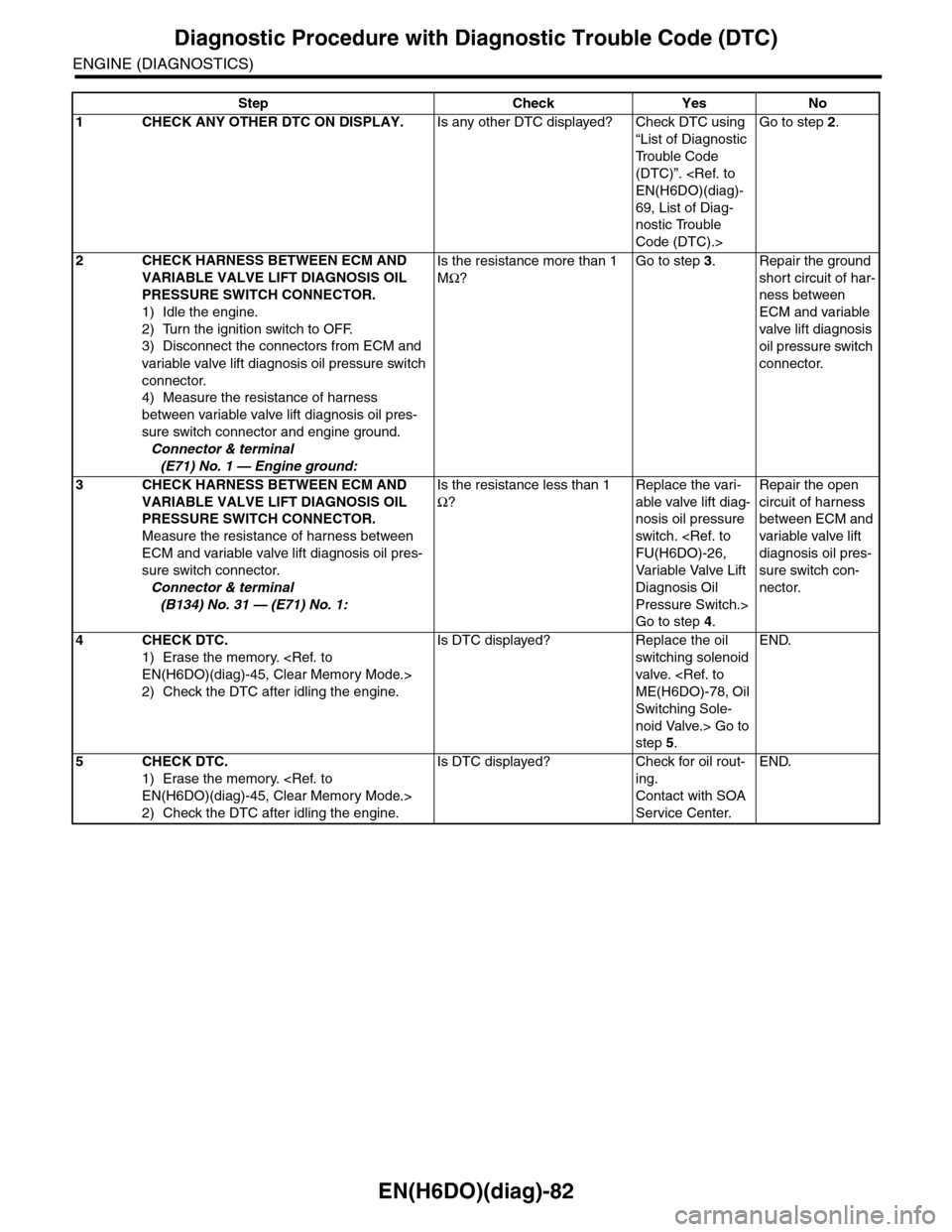
E: DTC P0026 INTAKE VALVE CONTROL SOLENOID CIRCUIT RANGE/PER-
FORMANCE (BANK 1)
DTC DETECTING CONDITION:
•Immediately at fault recognition
•GENERAL DESCRIPTION
CIRCUIT RANGE/PERFORMANCE (BANK 1), Diagnostic Trouble Code (DTC) Detecting Criteria.>
TROUBLE SYMPTOM:
Erroneous idling
CAUTION:
After repair or replacement of faulty parts, perform Clear Memory Mode
OPERATION, Clear Memory Mode.> and Inspection Mode
Inspection Mode.>.
WIRING DIAGRAM:
EN-03655
B134
31
B20
E19
ECM
B20
1234567891011 121314 15 16
1
VARIABLE VALVE LIFT DIAGNOSIS OIL PRESSURE SWITCH RH
E71
B134
85610 11 12 13 14 157213416
3019 20 2228 29
91718252123 24323126 2733 34
Page 1243 of 2453

EN(H6DO)(diag)-82
Diagnostic Procedure with Diagnostic Trouble Code (DTC)
ENGINE (DIAGNOSTICS)
Step Check Yes No
1CHECK ANY OTHER DTC ON DISPLAY.Is any other DTC displayed? Check DTC using
“List of Diagnostic
Tr o u b l e C o d e
(DTC)”.
EN(H6DO)(diag)-
69, List of Diag-
nostic Trouble
Code (DTC).>
Go to step 2.
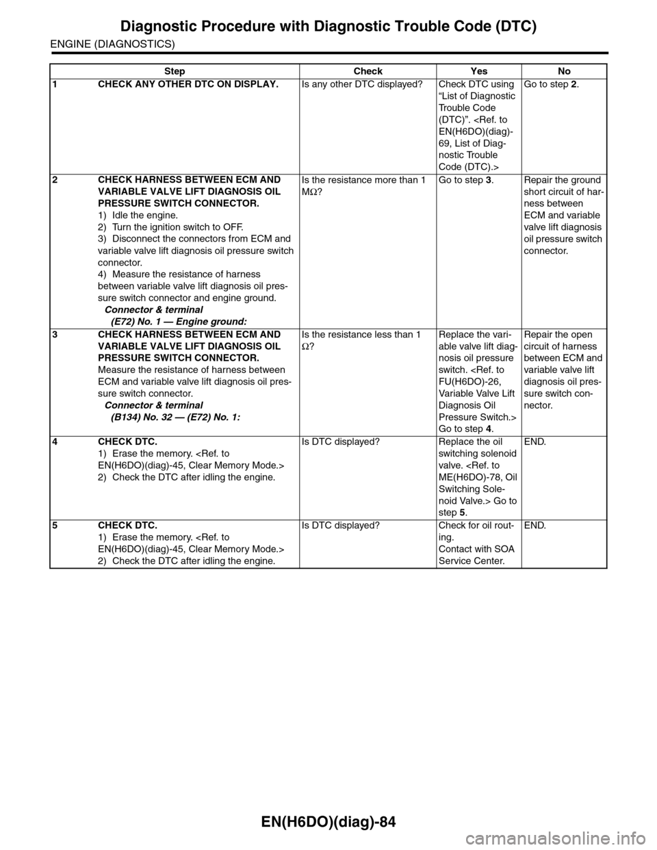
2CHECK HARNESS BETWEEN ECM AND
VARIABLE VALVE LIFT DIAGNOSIS OIL
PRESSURE SWITCH CONNECTOR.
1) Idle the engine.
2) Turn the ignition switch to OFF.
3) Disconnect the connectors from ECM and
variable valve lift diagnosis oil pressure switch
connector.
4) Measure the resistance of harness
between variable valve lift diagnosis oil pres-
sure switch connector and engine ground.
Connector & terminal
(E71) No. 1 — Engine ground:
Is the resistance more than 1
MΩ?
Go to step 3.Repair the ground
short circuit of har-
ness between
ECM and variable
valve lift diagnosis
oil pressure switch
connector.
3CHECK HARNESS BETWEEN ECM AND
VARIABLE VALVE LIFT DIAGNOSIS OIL
PRESSURE SWITCH CONNECTOR.
Measure the resistance of harness between
ECM and variable valve lift diagnosis oil pres-
sure switch connector.
Connector & terminal
(B134) No. 31 — (E71) No. 1:
Is the resistance less than 1
Ω?
Replace the vari-
able valve lift diag-
nosis oil pressure
switch.
FU(H6DO)-26,
Va r i a bl e Va l ve L i f t
Diagnosis Oil
Pressure Switch.>
Go to step 4.
Repair the open
circuit of harness
between ECM and
variable valve lift
diagnosis oil pres-
sure switch con-
nector.
4CHECK DTC.
1) Erase the memory.
EN(H6DO)(diag)-45, Clear Memory Mode.>
2) Check the DTC after idling the engine.
Is DTC displayed? Replace the oil
switching solenoid
valve.
ME(H6DO)-78, Oil
Switching Sole-
noid Valve.> Go to
step 5.
END.
5CHECK DTC.
1) Erase the memory.
EN(H6DO)(diag)-45, Clear Memory Mode.>
2) Check the DTC after idling the engine.
Is DTC displayed? Check for oil rout-
ing.
Contact with SOA
Service Center.
END.
Page 1244 of 2453
EN(H6DO)(diag)-83
Diagnostic Procedure with Diagnostic Trouble Code (DTC)
ENGINE (DIAGNOSTICS)
F: DTC P0028 INTAKE VALVE CONTROL SOLENOID CIRCUIT RANGE/PER-
FORMANCE (BANK 2)
DTC DETECTING CONDITION:
•Immediately at fault recognition
•GENERAL DESCRIPTION
CIRCUIT RANGE/PERFORMANCE (BANK 2), Diagnostic Trouble Code (DTC) Detecting Criteria.>
TROUBLE SYMPTOM:
Erroneous idling
CAUTION:
After repair or replacement of faulty parts, perform Clear Memory Mode
OPERATION, Clear Memory Mode.> and Inspection Mode
Inspection Mode.>.
WIRING DIAGRAM:
EN-03656
B134
32
B20
E110
ECM
B20
1234567891011 121314 15 16
VARIABLE VALVE LIFT DIAGNOSISOIL PRESSURE SWITCH LH
E72
B134
85610 11 12 13 14 157213416
3019 20 2228 29
91718252123 24323126 2733 34
Page 1245 of 2453

EN(H6DO)(diag)-84
Diagnostic Procedure with Diagnostic Trouble Code (DTC)
ENGINE (DIAGNOSTICS)
Step Check Yes No
1CHECK ANY OTHER DTC ON DISPLAY.Is any other DTC displayed? Check DTC using
“List of Diagnostic
Tr o u b l e C o d e
(DTC)”.
EN(H6DO)(diag)-
69, List of Diag-
nostic Trouble
Code (DTC).>
Go to step 2.
2CHECK HARNESS BETWEEN ECM AND
VARIABLE VALVE LIFT DIAGNOSIS OIL
PRESSURE SWITCH CONNECTOR.
1) Idle the engine.
2) Turn the ignition switch to OFF.
3) Disconnect the connectors from ECM and
variable valve lift diagnosis oil pressure switch
connector.
4) Measure the resistance of harness
between variable valve lift diagnosis oil pres-
sure switch connector and engine ground.
Connector & terminal
(E72) No. 1 — Engine ground:
Is the resistance more than 1
MΩ?
Go to step 3.Repair the ground
short circuit of har-
ness between
ECM and variable
valve lift diagnosis
oil pressure switch
connector.
3CHECK HARNESS BETWEEN ECM AND
VARIABLE VALVE LIFT DIAGNOSIS OIL
PRESSURE SWITCH CONNECTOR.
Measure the resistance of harness between
ECM and variable valve lift diagnosis oil pres-
sure switch connector.
Connector & terminal
(B134) No. 32 — (E72) No. 1:
Is the resistance less than 1
Ω?
Replace the vari-
able valve lift diag-
nosis oil pressure
switch.
FU(H6DO)-26,
Va r i a bl e Va l ve L i f t
Diagnosis Oil
Pressure Switch.>
Go to step 4.
Repair the open
circuit of harness
between ECM and
variable valve lift
diagnosis oil pres-
sure switch con-
nector.
4CHECK DTC.
1) Erase the memory.
EN(H6DO)(diag)-45, Clear Memory Mode.>
2) Check the DTC after idling the engine.
Is DTC displayed? Replace the oil
switching solenoid
valve.
ME(H6DO)-78, Oil
Switching Sole-
noid Valve.> Go to
step 5.
END.
5CHECK DTC.
1) Erase the memory.
EN(H6DO)(diag)-45, Clear Memory Mode.>
2) Check the DTC after idling the engine.
Is DTC displayed? Check for oil rout-
ing.
Contact with SOA
Service Center.
END.
Page 1567 of 2453
FU(H6DO)-6
General Description
FUEL INJECTION (FUEL SYSTEMS)
4. CRANKSHAFT POSITION, CAMSHAFT POSITION AND KNOCK SENSORS
(1) Crankshaft position sensor (6) Variable valve lift diagnosis oil
pressure switch RH
Tightening torque: N·m (kgf-m, ft-lb)
(2) Knock sensor RHT1: 6.4 (0.65, 4.7)
(3) Knock sensor LH (7) Variable valve lift diagnosis oil
pressure switch LH
T2: 17 (1.7, 12.5)
(4) Camshaft position sensor RHT3: 18 (1.8, 13.3)
(5) Camshaft position sensor LH (8) Oil temperature sensorT4: 25 (2.5, 18)
FU-02110
(6)
(4)
T2
T1
(3)
T4
(1)
(8)
T1
T3
(5)
T1
(2)
T4
(7)
T2
Page 1587 of 2453
FU(H6DO)-26
Variable Valve Lift Diagnosis Oil Pressure Switch
FUEL INJECTION (FUEL SYSTEMS)
12.Variable Valve Lift Diagnosis
Oil Pressure Switch
A: REMOVAL
1) Remove the collector cover.
2) Disconnect the ground cable from battery.
3) Remove the air intake chamber.
IN(H6DO)-6, REMOVAL, Air Intake Chamber.>
4) Disconnect the connector from variable valve lift
diagnosis oil pressure switch.
5) Remove the variable valve lift diagnosis oil pres-
sure switch.
•LH side
•RH side
B: INSTALLATION
Install in the reverse order of removal.
NOTE:
Apply liquid gasket to variable valve lift diagnosis
oil pressure switch threads.
Liquid gasket:
THREE BOND 1324 (Part No. 004403042) or
equivalent
Tightening torque:
17 N·m (1.7 kgf-m, 12.5 ft-lb)
FU-02136
FU-02137
Page 1624 of 2453

GD(H6DO)-12
Diagnostic Trouble Code (DTC) Detecting Criteria
GENERAL DESCRIPTION
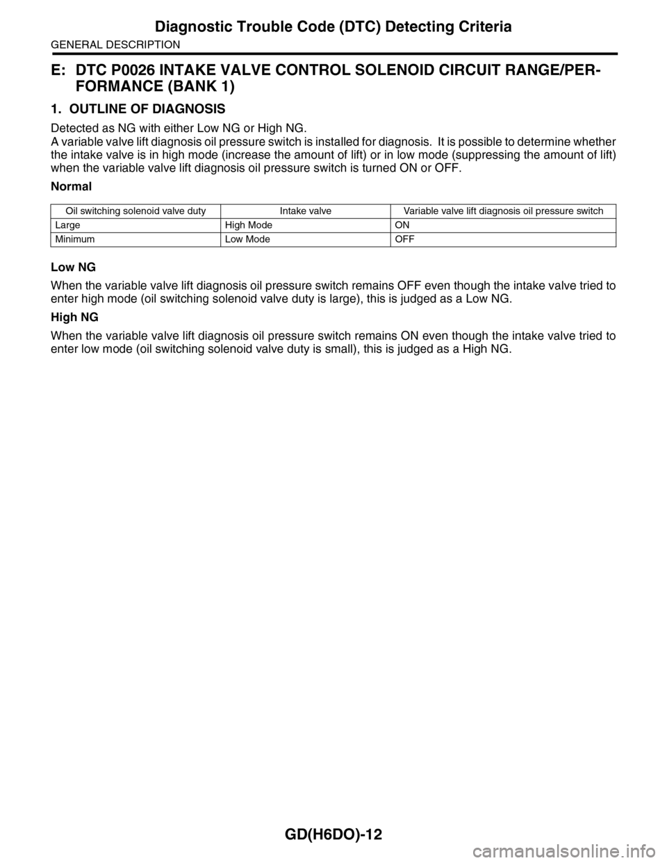
E: DTC P0026 INTAKE VALVE CONTROL SOLENOID CIRCUIT RANGE/PER-
FORMANCE (BANK 1)
1. OUTLINE OF DIAGNOSIS
Detected as NG with either Low NG or High NG.
A variable valve lift diagnosis oil pressure switch is installed for diagnosis. It is possible to determine whether
the intake valve is in high mode (increase the amount of lift) or in low mode (suppressing the amount of lift)
when the variable valve lift diagnosis oil pressure switch is turned ON or OFF.
Normal
Low NG
When the variable valve lift diagnosis oil pressure switch remains OFF even though the intake valve tried to
enter high mode (oil switching solenoid valve duty is large), this is judged as a Low NG.
High NG
When the variable valve lift diagnosis oil pressure switch remains ON even though the intake valve tried to
enter low mode (oil switching solenoid valve duty is small), this is judged as a High NG.
Oil switching solenoid valve duty Intake valve Variable valve lift diagnosis oil pressure switch
Large High Mode ON
Minimum Low Mode OFF
Page 1625 of 2453
GD(H6DO)-13
Diagnostic Trouble Code (DTC) Detecting Criteria
GENERAL DESCRIPTION
2. COMPONENT DESCRIPTION
The variable valve lift system optimizes the intake valve lift by switching between the low lift cam and the high
lift cam according to the engine RPM. The amount of intake valve lift is varied by controlling the oil switching
solenoid valve duty according to signals from the ECM.
3. ENABLE CONDITIONS
(A) When at low speed (B) When at high speed
(1) Oil switching solenoid valve
Secondary Parameters Enable Conditions
Battery voltage≥ 10.9 V
After engine starting≥ 6 sec.
Engine oil temperature≥ 0°C (0°F)
Va r i a b l e va l v e l i f t c o n t r o l O p e r a t i o n
EN-03119
(1)
(B)
(A)