2009 SUBARU TRIBECA check transmission fluid
[x] Cancel search: check transmission fluidPage 919 of 2453

PS-39
Pipe Assembly
POWER ASSISTED SYSTEM (POWER STEERING)
C: INSPECTION
Check all disassembled parts for wear, damage or other problems. Repair or replace the defective parts as
necessary.
CAUTION:
Although the surface layer materials of rubber hoses have excellent weathering resistance, heat re-
sistance and resistance for low temperature brittleness, they are likely to be damaged chemically by
brake fluid, battery electrolyte, engine oil and automatic transmission fluid and their service lives are
to be very shortened. Wipe off hoses immediately if any of these come into contact with the hoses.
Since resistances for heat or low temperature brittleness are gradually declining according to time
accumulation of hot or cold conditions for the hoses and their service lives are shortening accord-
ingly, it is necessary to perform careful inspection frequently when the vehicle is used in hot weather
areas, cold weather areas and a driving condition in which many steering operations are required in
short time.
Particularly continuous work of relief valve over 5 seconds causes to reduce service lives of the hos-
es, the oil pump, the fluid, etc. due to over heat.
Par t Maintenance par ts Corrective action
Pipe
•O–ring fitting surface damage
•Nut damage
•Pipe damage
Replace with a new part.
Clamp • Loose clamps Replace with a new part.
Hose
•Flare surface damage
•Flare nut damage
•Outer surface cracks
•Outer surface wear
•Clip damage
•End coupling or adapter for deformation
Replace with a new part.
Tr o u b l e P o s s i b l e c a u s e C o r r e c t i v e a c t i o n
Pressure hose burst
Excessive holding time of relief status Instruct customers.
Malfunction of the relief valve Replace the oil pump.
Poor cold character istic of fluid R eplace fluid.
Disconnection of the return
hose
Improper connection Repair.
Loosening of the clip Retighten.
Poor cold character istic of fluid R eplace fluid.
Fluid slightly leaking out of
hose
Wrong layout, tensioned Replace the hose.
Excessive play of engine due to deterioration of
engine mounting rubberReplace the parts if defective.
Improper stop position of pitching stopper Replace the parts if defective.
Crack on hose
Excessive holding time of relief statusReplace.
Instruct customers.
Excessive tightening torque for return hose clip Replace.
Power steer ing fluid, engine oil, electrolyte adhere
on the hose surface
Replace.
Be careful during service work.
To o m a n y u s e s i n e x t r e m e l y c o l d w e a t h e rReplace.
Instruct customers.
Page 1089 of 2453
VDC-8
VDC Control Module & Hydraulic Control Unit (VDCCM&H/U)
VEHICLE DYNAMICS CONTROL (VDC)
4) Connect the VDCCM&H/U connectors.
NOTE:
•Be sure to remove all foreign matter from inside
the connector before connecting.
•Make sure the VDCCM&H/U connector is se-
curely locked.
5) Bleed air from the brake system.
C: INSPECTION
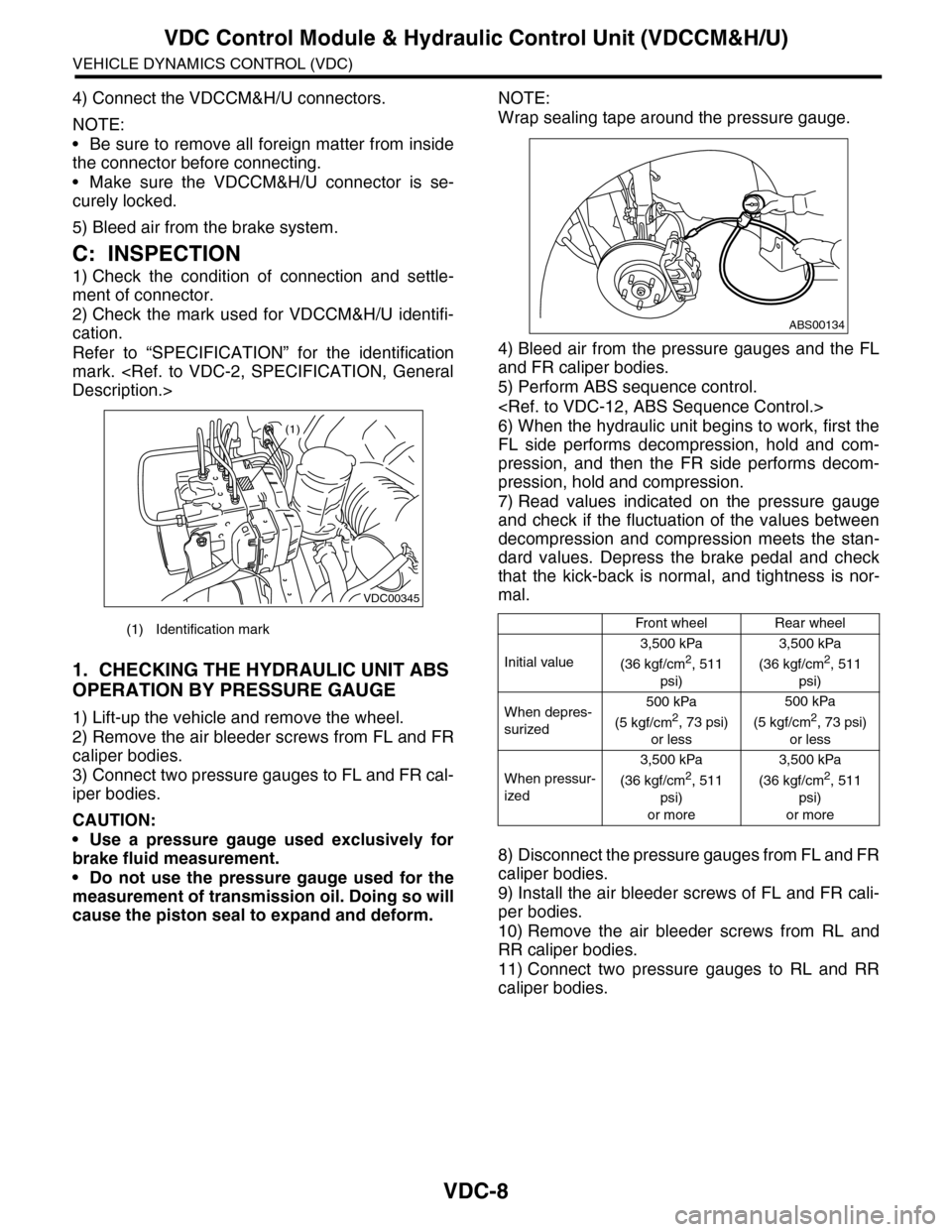
1) Check the condition of connection and settle-
ment of connector.
2) Check the mark used for VDCCM&H/U identifi-
cation.
Refer to “SPECIFICATION” for the identification
mark.
1. CHECKING THE HYDRAULIC UNIT ABS
OPERATION BY PRESSURE GAUGE
1) Lift-up the vehicle and remove the wheel.
2) Remove the air bleeder screws from FL and FR
caliper bodies.
3) Connect two pressure gauges to FL and FR cal-
iper bodies.
CAUTION:
•Use a pressure gauge used exclusively for
brake fluid measurement.
•Do not use the pressure gauge used for the
measurement of transmission oil. Doing so will
cause the piston seal to expand and deform.
NOTE:
Wrap sealing tape around the pressure gauge.
4) Bleed air from the pressure gauges and the FL
and FR caliper bodies.
5) Perform ABS sequence control.
6) When the hydraulic unit begins to work, first the
FL side performs decompression, hold and com-
pression, and then the FR side performs decom-
pression, hold and compression.
7) Read values indicated on the pressure gauge
and check if the fluctuation of the values between
decompression and compression meets the stan-
dard values. Depress the brake pedal and check
that the kick-back is normal, and tightness is nor-
mal.
8) Disconnect the pressure gauges from FL and FR
caliper bodies.
9) Install the air bleeder screws of FL and FR cali-
per bodies.
10) Remove the air bleeder screws from RL and
RR caliper bodies.
11) Connect two pressure gauges to RL and RR
caliper bodies.
(1) Identification mark
VDC00345
(1)
Front wheelRear wheel
Initial value
3,500 kPa
(36 kgf/cm2, 511
psi)
3,500 kPa
(36 kgf/cm2, 511
psi)
When depres-
surized
500 kPa
(5 kgf/cm2, 73 psi)
or less
500 kPa
(5 kgf/cm2, 73 psi)
or less
When pressur-
ized
3,500 kPa
(36 kgf/cm2, 511
psi)
or more
3,500 kPa
(36 kgf/cm2, 511
psi)
or more
ABS00134
Page 1090 of 2453
VDC-9
VDC Control Module & Hydraulic Control Unit (VDCCM&H/U)
VEHICLE DYNAMICS CONTROL (VDC)
12) Bleed air from the brake system.
13) Bleed air from RL and RR caliper bodies, and
pressure gauge.
14) Perform ABS sequence control.
15) When the hydraulic unit begins to work, first the
RR side performs decompression, hold and com-
pression, and then the RL side performs decom-
pression, hold and compression.
16) Read values indicated on the pressure gauge
and check if the fluctuation of the values between
decompression and compression meets specifica-
tion. Depress the brake pedal and check that the
kick-back is normal, and tightness is normal.
17) Disconnect the pressure gauge from the RL
and RR caliper bodies.
18) Install the air bleeder screws of RL and RR cal-
iper bodies.
19) Bleed air from the brake system.
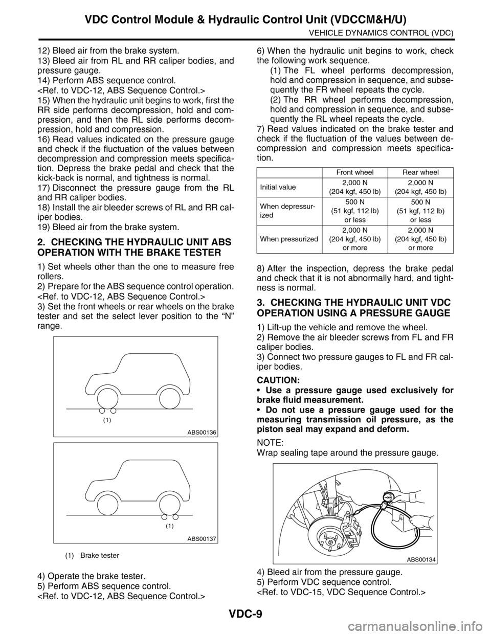
2. CHECKING THE HYDRAULIC UNIT ABS
OPERATION WITH THE BRAKE TESTER
1) Set wheels other than the one to measure free
rollers.
2) Prepare for the ABS sequence control operation.
3) Set the front wheels or rear wheels on the brake
tester and set the select lever position to the “N”
range.
4) Operate the brake tester.
5) Perform ABS sequence control.
6) When the hydraulic unit begins to work, check
the following work sequence.
(1) The FL wheel performs decompression,
hold and compression in sequence, and subse-
quently the FR wheel repeats the cycle.
(2) The RR wheel performs decompression,
hold and compression in sequence, and subse-
quently the RL wheel repeats the cycle.
7) Read values indicated on the brake tester and
check if the fluctuation of the values between de-
compression and compression meets specifica-
tion.
8) After the inspection, depress the brake pedal
and check that it is not abnormally hard, and tight-
ness is normal.
3. CHECKING THE HYDRAULIC UNIT VDC
OPERATION USING A PRESSURE GAUGE
1) Lift-up the vehicle and remove the wheel.
2) Remove the air bleeder screws from FL and FR
caliper bodies.
3) Connect two pressure gauges to FL and FR cal-
iper bodies.
CAUTION:
•Use a pressure gauge used exclusively for
brake fluid measurement.
•Do not use a pressure gauge used for the
measuring transmission oil pressure, as the
piston seal may expand and deform.
NOTE:
Wrap sealing tape around the pressure gauge.
4) Bleed air from the pressure gauge.
5) Perform VDC sequence control.
(1) Brake tester
ABS00136
(1)
ABS00137
(1)
Front wheelRear wheel
Initial value2,000 N
(204 kgf, 450 lb)
2,000 N
(204 kgf, 450 lb)
When depressur-
ized
500 N
(51 kgf, 112 lb)
or less
500 N
(51 kgf, 112 lb)
or less
When pressurized
2,000 N
(204 kgf, 450 lb)
or more
2,000 N
(204 kgf, 450 lb)
or more
ABS00134
Page 1999 of 2453
PM-16
Automatic Transmission Fluid
PERIODIC MAINTENANCE SERVICES
11. Automatic Transmission Fluid
A: INSPECTION
CAUTION:
The level of ATF varies with fluid temperature.
Pay attention to the fluid temperature when
checking ATF level.
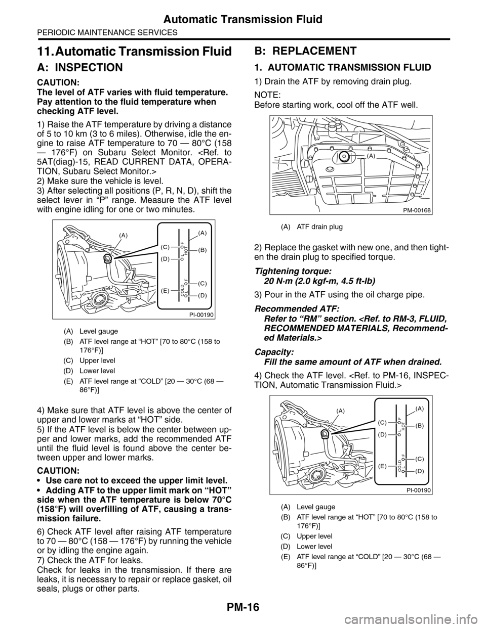
1) Raise the ATF temperature by driving a distance
of 5 to 10 km (3 to 6 miles). Otherwise, idle the en-
gine to raise ATF temperature to 70 — 80°C (158
— 176°F) on Subaru Select Monitor.
TION, Subaru Select Monitor.>
2) Make sure the vehicle is level.
3) After selecting all positions (P, R, N, D), shift the
select lever in “P” range. Measure the ATF level
with engine idling for one or two minutes.
4) Make sure that ATF level is above the center of
upper and lower marks at “HOT” side.
5) If the ATF level is below the center between up-
per and lower marks, add the recommended ATF
until the fluid level is found above the center be-
tween upper and lower marks.
CAUTION:
•Use care not to exceed the upper limit level.
•Adding ATF to the upper limit mark on “HOT”
side when the ATF temperature is below 70°C
(158°F) will overfilling of ATF, causing a trans-
mission failure.
6) Check ATF level after raising ATF temperature
to 70 — 80°C (158 — 176°F) by running the vehicle
or by idling the engine again.
7) Check the ATF for leaks.
Check for leaks in the transmission. If there are
leaks, it is necessary to repair or replace gasket, oil
seals, plugs or other parts.
B: REPLACEMENT
1. AUTOMATIC TRANSMISSION FLUID
1) Drain the ATF by removing drain plug.
NOTE:
Before starting work, cool off the ATF well.
2) Replace the gasket with new one, and then tight-
en the drain plug to specified torque.
Tightening torque:
20 N·m (2.0 kgf-m, 4.5 ft-lb)
3) Pour in the ATF using the oil charge pipe.
Recommended ATF:
Refer to “RM” section.
ed Materials.>
Capacity:
Fill the same amount of ATF when drained.
4) Check the ATF level.
(A) Level gauge
(B) ATF level range at “HOT” [70 to 80°C (158 to
176°F)]
(C) Upper level
(D) Lower level
(E) ATF level range at “COLD” [20 — 30°C (68 —
86°F)]
PI-00190
(A)
(C)
(D)
(E)(D)
(C)
(B)
(A)
F
L
F
HOT
LCOLD
(A) ATF drain plug
(A) Level gauge
(B) ATF level range at “HOT” [70 to 80°C (158 to
176°F)]
(C) Upper level
(D) Lower level
(E) ATF level range at “COLD” [20 — 30°C (68 —
86°F)]
PM-00168
(A)
PI-00190
(A)
(C)
(D)
(E)(D)
(C)
(B)
(A)
F
L
F
HOT
LCOLD
Page 2042 of 2453
5AT-26
Automatic Transmission Fluid
AUTOMATIC TRANSMISSION
2. Automatic Transmission Fluid
A: INSPECTION
NOTE:
The level of ATF varies with fluid temperature. Pay
attention to the ATF temperature when checking
ATF level.
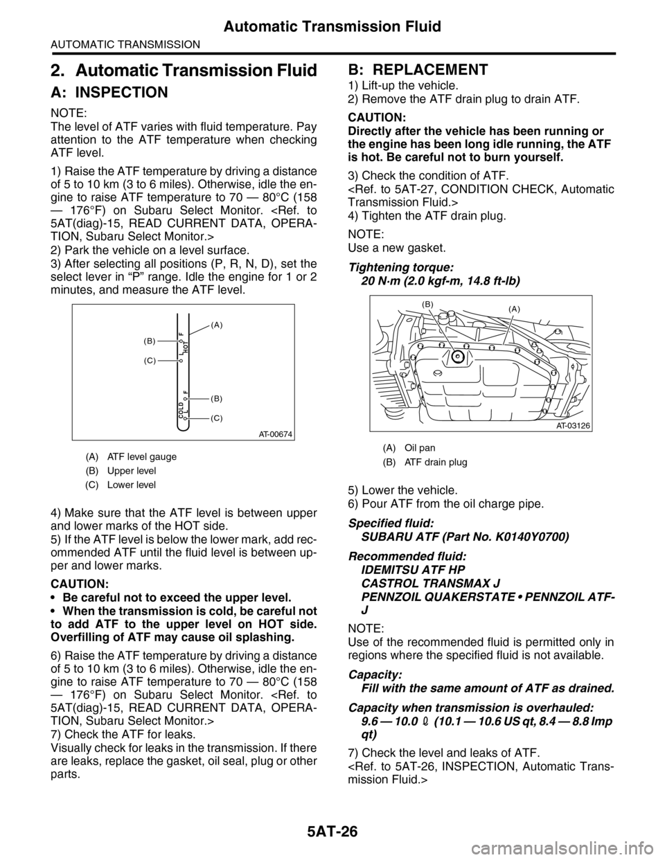
1) Raise the ATF temperature by driving a distance
of 5 to 10 km (3 to 6 miles). Otherwise, idle the en-
gine to raise ATF temperature to 70 — 80°C (158
— 176°F) on Subaru Select Monitor.
TION, Subaru Select Monitor.>
2) Park the vehicle on a level surface.
3) After selecting all positions (P, R, N, D), set the
select lever in “P” range. Idle the engine for 1 or 2
minutes, and measure the ATF level.
4) Make sure that the ATF level is between upper
and lower marks of the HOT side.
5) If the ATF level is below the lower mark, add rec-
ommended ATF until the fluid level is between up-
per and lower marks.
CAUTION:
•Be careful not to exceed the upper level.
•When the transmission is cold, be careful not
to add ATF to the upper level on HOT side.
Overfilling of ATF may cause oil splashing.
6) Raise the ATF temperature by driving a distance
of 5 to 10 km (3 to 6 miles). Otherwise, idle the en-
gine to raise ATF temperature to 70 — 80°C (158
— 176°F) on Subaru Select Monitor.
TION, Subaru Select Monitor.>
7) Check the ATF for leaks.
Visually check for leaks in the transmission. If there
are leaks, replace the gasket, oil seal, plug or other
parts.
B: REPLACEMENT
1) Lift-up the vehicle.
2) Remove the ATF drain plug to drain ATF.
CAUTION:
Directly after the vehicle has been running or
the engine has been long idle running, the ATF
is hot. Be careful not to burn yourself.
3) Check the condition of ATF.
4) Tighten the ATF drain plug.
NOTE:
Use a new gasket.
Tightening torque:
20 N·m (2.0 kgf-m, 14.8 ft-lb)
5) Lower the vehicle.
6) Pour ATF from the oil charge pipe.
Specified fluid:
SUBARU ATF (Part No. K0140Y0700)
Recommended fluid:
IDEMITSU ATF HP
CASTROL TRANSMAX J
PENNZOIL QUAKERSTATE • PENNZOIL ATF-
J
NOTE:
Use of the recommended fluid is permitted only in
regions where the specified fluid is not available.
Capacity:
Fill with the same amount of ATF as drained.
Capacity when transmission is overhauled:
9.6 — 10.0 2 ( 1 0 . 1 — 1 0 . 6 U S q t , 8 . 4 — 8 . 8 I m p
qt)
7) Check the level and leaks of ATF.
(A) ATF level gauge
(B) Upper level
(C) Lower level
AT-00674
COLDLF
HOTLF(C)
(C)
(B)
(B)
(A)
(A) Oil pan
(B) ATF drain plug
(A)
AT-03126
(B)
Page 2043 of 2453
5AT-27
Automatic Transmission Fluid
AUTOMATIC TRANSMISSION
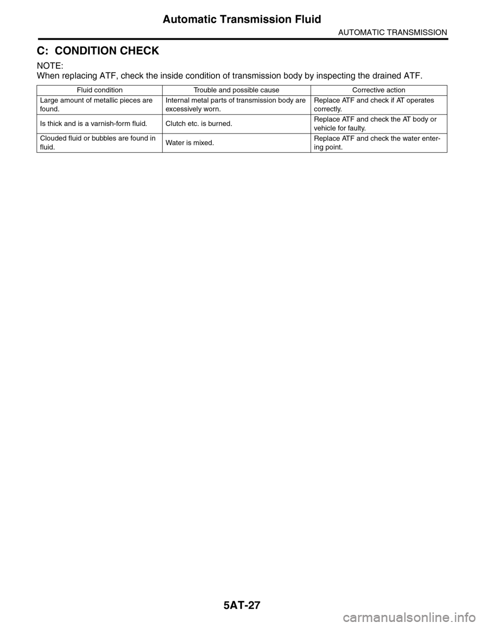
C: CONDITION CHECK
NOTE:
When replacing ATF, check the inside condition of transmission body by inspecting the drained ATF.
Fluid condition Trouble and possible cause Corrective action
Large amount of metallic pieces are
found.
Internal metal parts of transmission body are
excessively wor n.
Replace ATF and check if AT operates
correctly.
Is thick and is a varnish-form fluid. Clutch etc. is burned.Replace ATF and check the AT body or
vehicle for faulty.
Clouded fluid or bubbles are found in
fluid.Water is mixed.Replace ATF and check the water enter-
ing point.
Page 2047 of 2453
5AT-31
Time Lag Test
AUTOMATIC TRANSMISSION
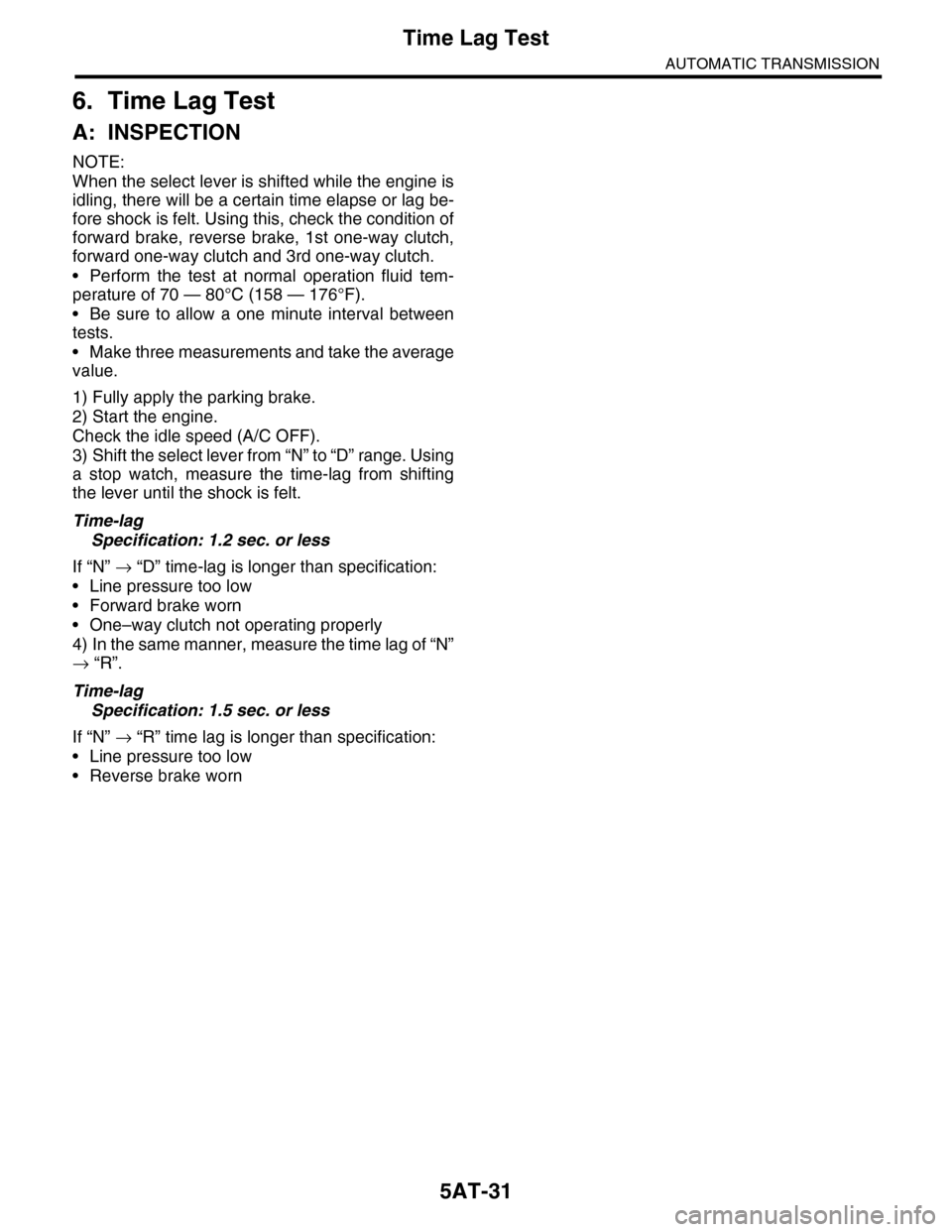
6. Time Lag Test
A: INSPECTION
NOTE:
When the select lever is shifted while the engine is
idling, there will be a certain time elapse or lag be-
fore shock is felt. Using this, check the condition of
forward brake, reverse brake, 1st one-way clutch,
forward one-way clutch and 3rd one-way clutch.
•Perform the test at normal operation fluid tem-
perature of 70 — 80°C (158 — 176°F).
•Be sure to allow a one minute interval between
tests.
•Make three measurements and take the average
value.
1) Fully apply the parking brake.
2) Start the engine.
Check the idle speed (A/C OFF).
3) Shift the select lever from “N” to “D” range. Using
a stop watch, measure the time-lag from shifting
the lever until the shock is felt.
Time-lag
Specification: 1.2 sec. or less
If “N” → “D” time-lag is longer than specification:
•Line pressure too low
•Forward brake worn
•One–way clutch not operating properly
4) In the same manner, measure the time lag of “N”
→ “R”.
Time-lag
Specification: 1.5 sec. or less
If “N” → “R” time lag is longer than specification:
•Line pressure too low
•Reverse brake worn
Page 2060 of 2453
5AT-44
Extension Case Oil Seal
AUTOMATIC TRANSMISSION
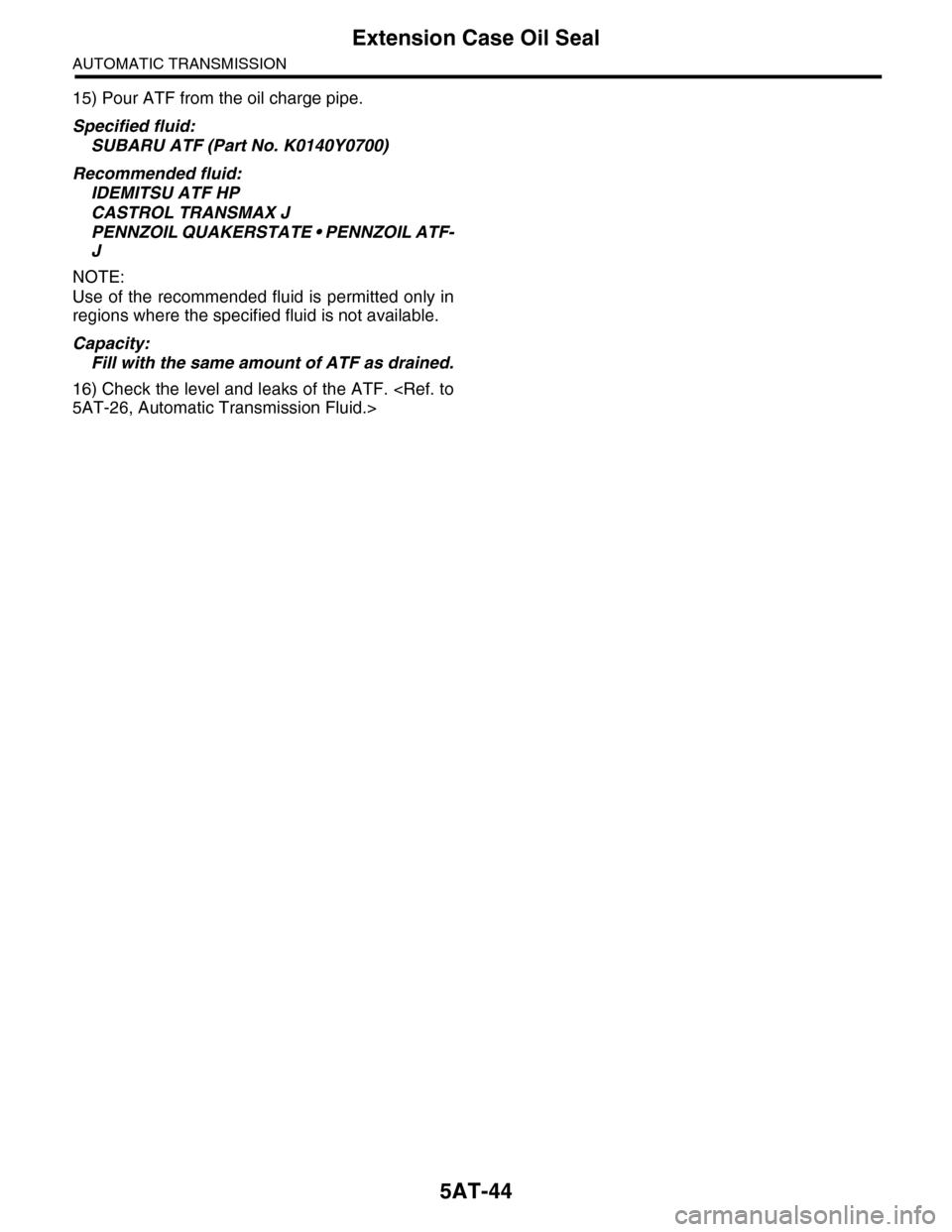
15) Pour ATF from the oil charge pipe.
Specified fluid:
SUBARU ATF (Part No. K0140Y0700)
Recommended fluid:
IDEMITSU ATF HP
CASTROL TRANSMAX J
PENNZOIL QUAKERSTATE • PENNZOIL ATF-
J
NOTE:
Use of the recommended fluid is permitted only in
regions where the specified fluid is not available.
Capacity:
Fill with the same amount of ATF as drained.
16) Check the level and leaks of the ATF.