Page 2064 of 2453
5AT-48
Front Vehicle Speed Sensor
AUTOMATIC TRANSMISSION
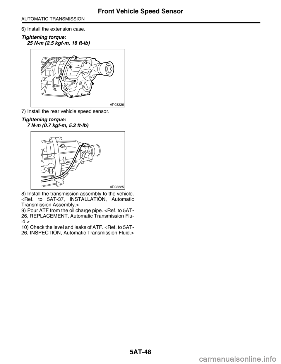
6) Install the extension case.
Tightening torque:
25 N·m (2.5 kgf-m, 18 ft-lb)
7) Install the rear vehicle speed sensor.
Tightening torque:
7 N·m (0.7 kgf-m, 5.2 ft-lb)
8) Install the transmission assembly to the vehicle.
Transmission Assembly.>
9) Pour ATF from the oil charge pipe.
26, REPLACEMENT, Automatic Transmission Flu-
id.>
10) Check the level and leaks of ATF.
26, INSPECTION, Automatic Transmission Fluid.>
AT-03226
AT-03225
Page 2067 of 2453
5AT-51
Rear Vehicle Speed Sensor
AUTOMATIC TRANSMISSION
7) Install the rear vehicle speed sensor and turbine
speed sensor 1, and then fasten the harness.
Tightening torque:
7 N·m (0.7 kgf-m, 5.2 ft-lb)
8) Install a new aluminum washer and oil cooler
pipe.
Tightening torque:
40 N·m (4.1 kgf-m, 29.5 ft-lb) (ATF inlet pipe)
45 N·m (4.6 kgf-m, 33.2 ft-lb) (ATF outlet pipe)
9) Install the oil charge pipe.
STALLATION, Oil Charge Pipe.>
10) Install the transmission rear crossmember bolt.
Tightening torque:
70 N·m (7.1 kgf-m, 51.6 ft-lb)
11) Install the propeller shaft.
STALLATION, Propeller Shaft.>
12) Install the heat shield cover.
13) Install the rear exhaust pipe and muffler.
to EX(H6DO)-7, INSTALLATION, Rear Exhaust
Pipe.>
Muffler.>
14) Lower the vehicle.
15) Install the transmission connector to the stay,
and then connect the connector.
16) Install the air intake chamber.
IN(H6DO)-6, INSTALLATION, Air Intake Cham-
ber.>
17) Pour ATF from the oil charge pipe.
5AT-26, REPLACEMENT, Automatic Transmis-
sion Fluid.>
18) Check the level and leaks of ATF.
26, INSPECTION, Automatic Transmission Fluid.>
Page 2070 of 2453
5AT-54
Control Valve Body
AUTOMATIC TRANSMISSION
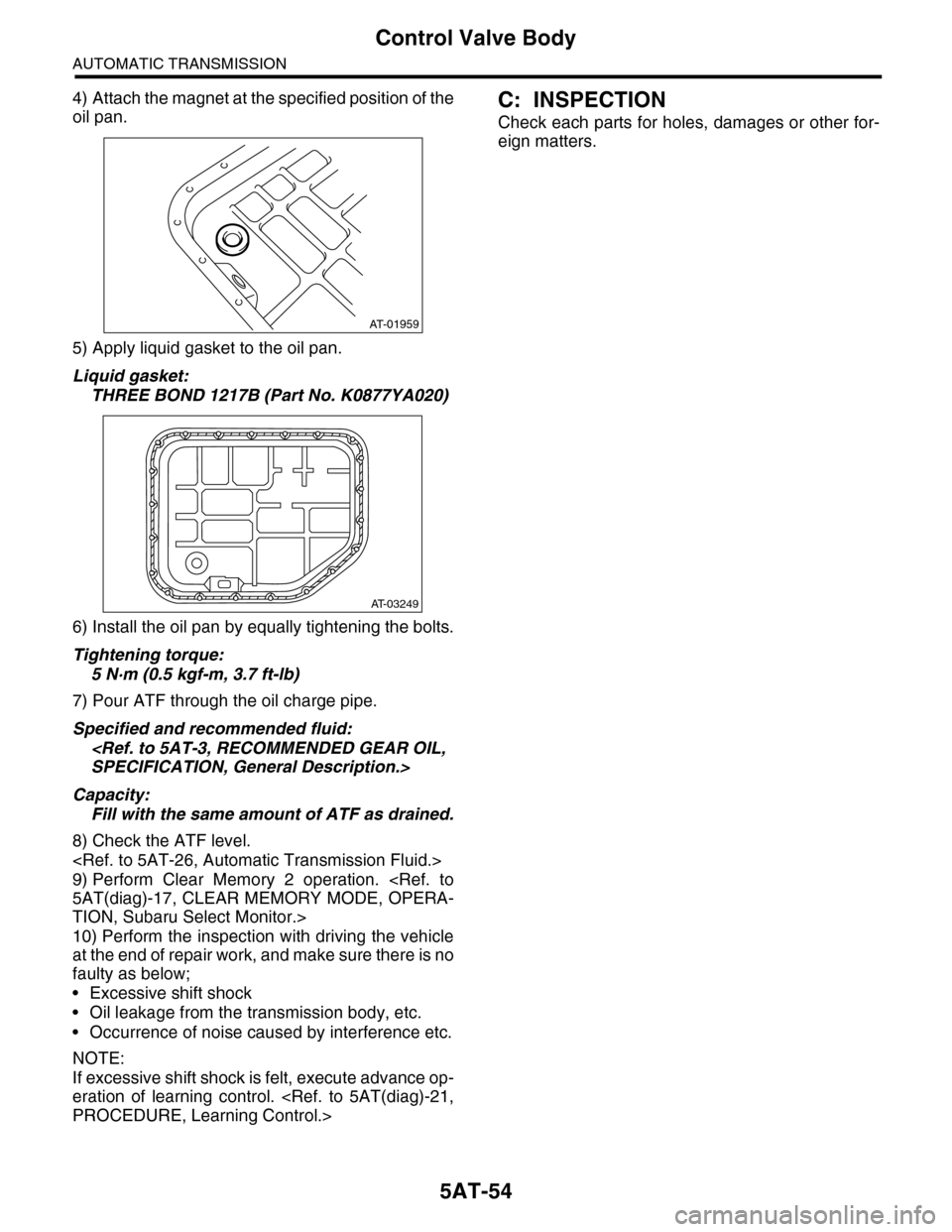
4) Attach the magnet at the specified position of the
oil pan.
5) Apply liquid gasket to the oil pan.
Liquid gasket:
THREE BOND 1217B (Part No. K0877YA020)
6) Install the oil pan by equally tightening the bolts.
Tightening torque:
5 N·m (0.5 kgf-m, 3.7 ft-lb)
7) Pour ATF through the oil charge pipe.
Specified and recommended fluid:
SPECIFICATION, General Description.>
Capacity:
Fill with the same amount of ATF as drained.
8) Check the ATF level.
9) Perform Clear Memory 2 operation.
5AT(diag)-17, CLEAR MEMORY MODE, OPERA-
TION, Subaru Select Monitor.>
10) Perform the inspection with driving the vehicle
at the end of repair work, and make sure there is no
faulty as below;
•Excessive shift shock
•Oil leakage from the transmission body, etc.
•Occurrence of noise caused by interference etc.
NOTE:
If excessive shift shock is felt, execute advance op-
eration of learning control.
PROCEDURE, Learning Control.>
C: INSPECTION
Check each parts for holes, damages or other for-
eign matters.
AT-01959
AT-03249
Page 2071 of 2453
5AT-55
ATF Filter
AUTOMATIC TRANSMISSION
18.ATF Filter
A: REMOVAL
1) Remove the front bumper.
MOVAL, Front Bumper.>
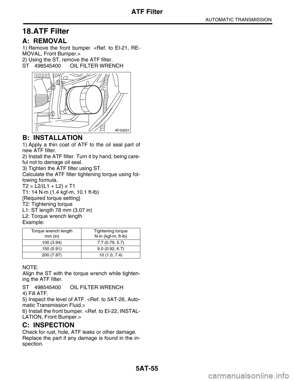
2) Using the ST, remove the ATF filter.
ST 498545400 OIL FILTER WRENCH
B: INSTALLATION
1) Apply a thin coat of ATF to the oil seal part of
new ATF filter.
2) Install the ATF filter. Turn it by hand, being care-
ful not to damage oil seal.
3) Tighten the ATF filter using ST.
Calculate the ATF filter tightening torque using fol-
lowing formula.
T2 = L2/(L1 + L2) × T1
T1: 14 N·m (1.4 kgf-m, 10.1 ft-lb)
[Required torque setting]
T2: Tightening torque
L1: ST length 78 mm (3.07 in)
L2: Torque wrench length
Example:
NOTE:
Align the ST with the torque wrench while tighten-
ing the ATF filter.
ST 498545400 OIL FILTER WRENCH
4) Fill ATF.
5) Inspect the level of ATF.
matic Transmission Fluid.>
6) Install the front bumper.
LATION, Front Bumper.>
C: INSPECTION
Check for rust, hole, ATF leaks or other damage.
Replace the part if any damage is found in the in-
spection.
To r q u e w r e n c h l e n g t h
mm (in)
Tightening torque
N·m (kgf-m, ft-lb)
100 (3.94) 7.7 (0.79, 5.7)
150 (5.91) 9.0 (0.92, 6.7)
200 (7.87) 10 (1.0, 7.4)
AT-03251
Page 2075 of 2453
5AT-59
ATF Cooler Pipe & Hose
AUTOMATIC TRANSMISSION
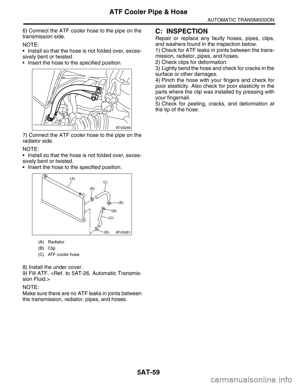
6) Connect the ATF cooler hose to the pipe on the
transmission side.
NOTE:
•Install so that the hose is not folded over, exces-
sively bent or twisted.
•Insert the hose to the specified position.
7) Connect the ATF cooler hose to the pipe on the
radiator side.
NOTE:
•Install so that the hose is not folded over, exces-
sively bent or twisted.
•Insert the hose to the specified position.
8) Install the under cover.
9) Fill ATF.
sion Fluid.>
NOTE:
Make sure there are no ATF leaks in joints between
the transmission, radiator, pipes, and hoses.
C: INSPECTION
Repair or replace any faulty hoses, pipes, clips,
and washers found in the inspection below.
1) Check for ATF leaks in joints between the trans-
mission, radiator, pipes, and hoses.
2) Check clips for deformation.
3) Lightly bend the hose and check for cracks in the
surface or other damages.
4) Pinch the hose with your fingers and check for
poor elasticity. Also check for poor elasticity in the
parts where the clip was installed by pressing with
your fingernail.
5) Check for peeling, cracks, and deformation at
the tip of the hose.
(A) Radiator
(B) Clip
(C) ATF cooler hose
AT-03246
AT-03261
(A)
(B)
C)
(C)
(B)
(B)
(B)
Page 2122 of 2453
5AT(diag)-5
General Description
AUTOMATIC TRANSMISSION (DIAGNOSTICS)
3. General Description
A: CAUTION
•SRS AIRBAG SYSTEM
The airbag system wiring harness is routed near
the TCM.
CAUTION:
•All air bag system wiring harnesses and con-
nectors are colored yellow. Do not use an elec-
tric test equipment to check these circuits.
•Be careful not to damage the airbag system
wiring harness when performing diagnostics or
servicing the TCM.
•MEASUREMENT
When measuring the voltage and resistance of the
ECM, TCM or each sensor, use a tapered pin with
a diameter of less than 0.64 mm (0.025 in) in order
to avoid poor contact. Do not insert a pin of more
than 0.65 mm (0.026 in) diameter.
B: INSPECTION
1. BATTERY
Measure the battery voltage and specific gravity of
electrolyte.
Standard voltage: 12 V or more
Specific gravity: 1.260 or more
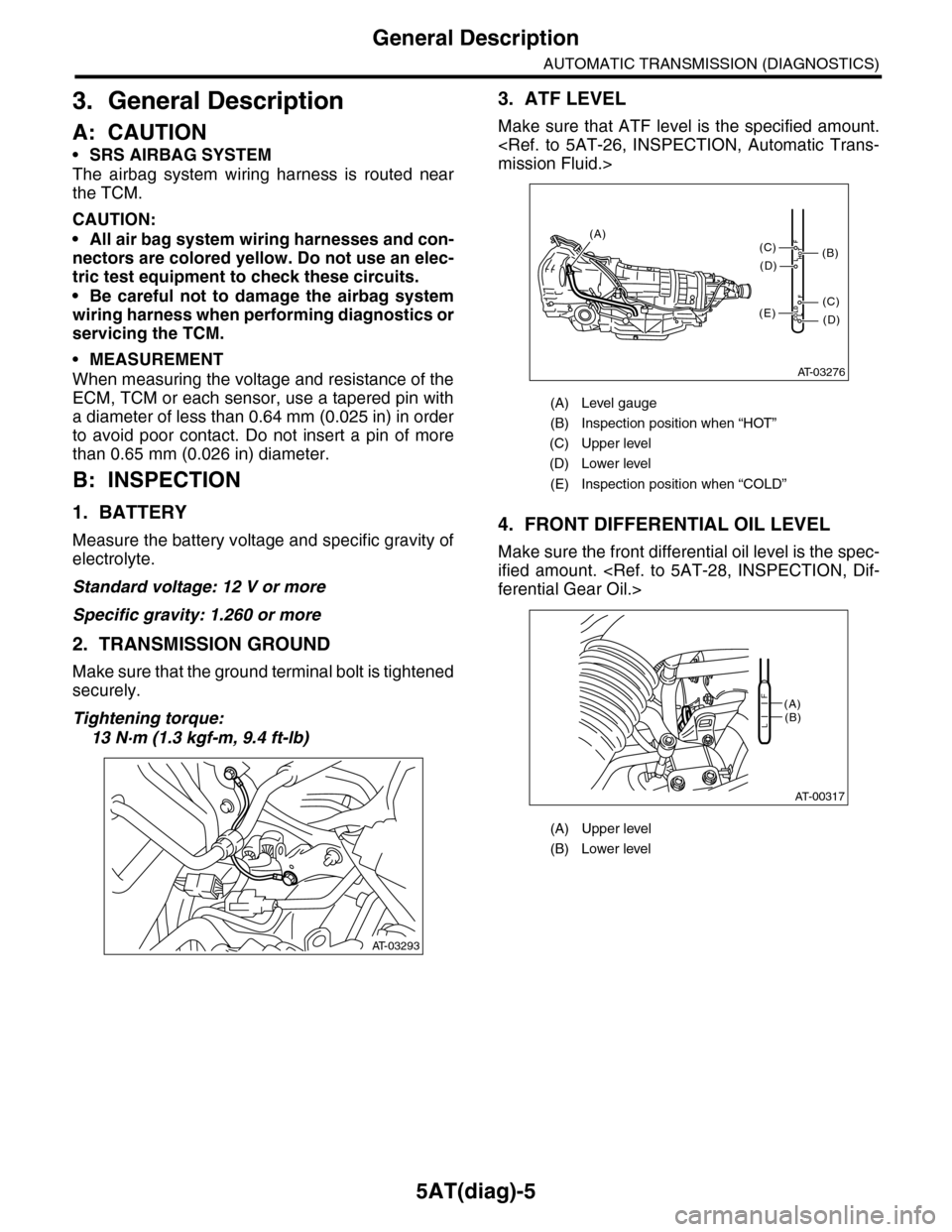
2. TRANSMISSION GROUND
Make sure that the ground terminal bolt is tightened
securely.
Tightening torque:
13 N·m (1.3 kgf-m, 9.4 ft-lb)
3. ATF LEVEL
Make sure that ATF level is the specified amount.
mission Fluid.>
4. FRONT DIFFERENTIAL OIL LEVEL
Make sure the front differential oil level is the spec-
ified amount.
ferential Gear Oil.>
AT-03293
(A) Level gauge
(B) Inspection position when “HOT”
(C) Upper level
(D) Lower level
(E) Inspection position when “COLD”
(A) Upper level
(B) Lower level
AT-03276
COLDLF
HOTLF
(C)
(D)
(C)
(D)
(E)
(B)
(A)
AT-00317
(A)(B)L
F
Page 2236 of 2453
5AT(diag)-119
Diagnostic Procedure with Diagnostic Trouble Code (DTC)
AUTOMATIC TRANSMISSION (DIAGNOSTICS)
AQ:DTC P1840 TRANSMISSION FLUID PRESSURE SENSOR/SWITCH A CIR-
CUIT
DTC DETECTING CONDITION:
Front brake oil pressure switch malfunction
TROUBLE SYMPTOM:
Excessive shift shock
NOTE:
Refer to DTC P0751 for diagnostic procedure.
PERFORMANCE OR STUCK OFF, Diagnostic Procedure with Diagnostic Trouble Code (DTC).>
AR:DTC P1842 TRANSMISSION FLUID PRESSURE SENSOR/SWITCH C CIR-
CUIT
DTC DETECTING CONDITION:
Input clutch oil pressure switch is malfunction.
TROUBLE SYMPTOM:
Excessive shift shock
NOTE:
Refer to DTC P0756 for diagnostic procedure.
PERFORMANCE OR STUCK OFF, Diagnostic Procedure with Diagnostic Trouble Code (DTC).>
AS:DTC P1843 TRANSMISSION FLUID PRESSURE SENSOR/SWITCH D CIR-
CUIT
DTC DETECTING CONDITION:
Direct clutch oil pressure switch malfunction.
TROUBLE SYMPTOM:
Excessive shift shock
NOTE:
Refer to DTC P0766 for diagnostic procedure.
PERFORMANCE OR STUCK OFF, Diagnostic Procedure with Diagnostic Trouble Code (DTC).>
AT:DTC P1844 TRANSMISSION FLUID PRESSURE SENSOR/SWITCH E CIR-
CUIT
DTC DETECTING CONDITION:
High & low reverse clutch oil pressure switch malfunction.
TROUBLE SYMPTOM:
Excessive shift shock
NOTE:
Refer to DTC P0761 for diagnostic procedure.
PERFORMANCE OR STUCK OFF, Diagnostic Procedure with Diagnostic Trouble Code (DTC).>
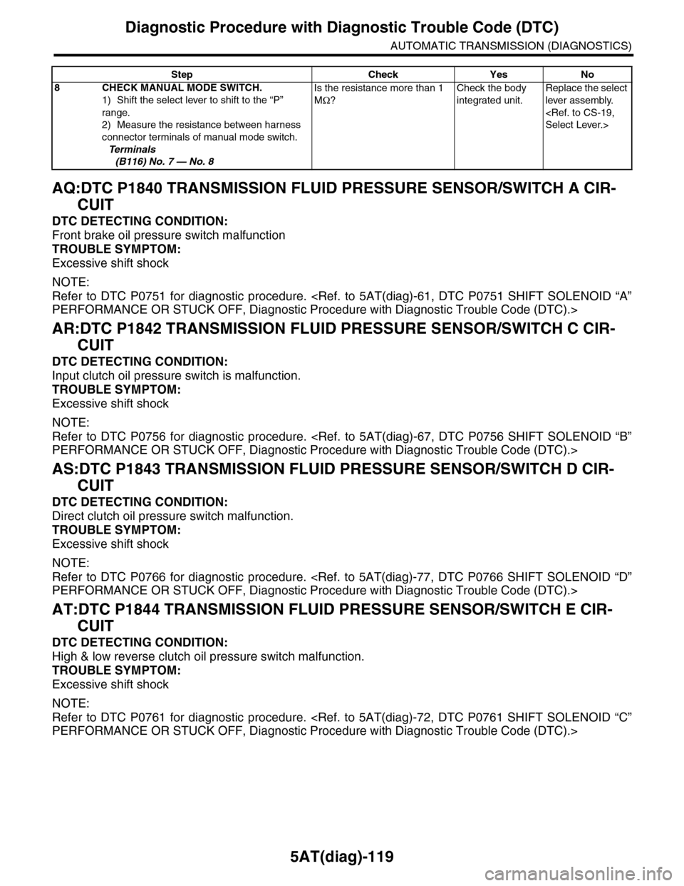
8CHECK MANUAL MODE SWITCH.
1) Shift the select lever to shift to the “P”
range.
2) Measure the resistance between harness
connector terminals of manual mode switch.
Te r m i n a l s
(B116) No. 7 — No. 8
Is the resistance more than 1
MΩ?
Check the body
integrated unit.
Replace the select
lever assembly.
Select Lever.>
Step Check Yes No