Page 297 of 2453
GW-2
General Description
GLASS/WINDOWS/MIRRORS
1. General Description
A: COMPONENT
1. FIXED GLASS
(1) Windshield glass (6) Spacer (10) Fastener
(2) Dam rubber (7) Fastener (11) Rear quarter glass
(3) Molding front (8) Seal (12) Rear gate glass
(4) Rearview mirror mount (9) Front quarter glass (13) Glass clip pin
(5) Locating pin
Page 300 of 2453
GW-5
General Description
GLASS/WINDOWS/MIRRORS
4. MIRROR
B: CAUTION
•When electrical connectors are disconnected, always conduct an operational check after connecting them
again.
•Avoid impact and damage to the glass.
C: PREPARATION TOOL
1. GENERAL TOOL
(1) Outer mirror (4) Side turn signal lightTightening torque: N·m (kgf-m, ft-lb)
(2) Mirror (5) Rearview mirrorT: 2 (0.2, 1.5)
(3) Scalp cap (6) Mount
TOOL NAME REMARKS
Circuit tester Used for checking voltage and continuity.
Piano wire Used for removing the window glass.
Windshield glass knife Used for removing the window glass.
TO RX® T20Used for removing and installing the rearview mirror.
GW-00476
(5)
(6)
(2)
(3)
(4)
(1)
T
Page 308 of 2453
GW-13
Outer Mirror Assembly
GLASS/WINDOWS/MIRRORS
8. Outer Mirror Assembly
A: REMOVAL
1) Remove the mirror gusset cover.
2) Remove the door trim.
AL, Door Trim.>
3) Disconnect the mirror connector.
4) Remove the screws to remove outer mirror as-
sembly.
B: INSTALLATION
Install in the reverse order of removal.
C: INSPECTION
Check that the rearview mirror moves properly
when the battery voltage is applied to terminals.
Replace the outer mirror assembly if defective.
(1) Clip
(2) Hook
GW-00484
(2)
(1)
GW-00483
Mirror movement Terminal No.
OFF —
UP 5 (+) and 6 (–)
DOWN 6 (+) or 5 (–)
LEFT 8 (+) and 7 (–)
RIGHT 7 (+) or 8 (–)
Page 324 of 2453
GW-29
Rearview Mirror
GLASS/WINDOWS/MIRRORS
20.Rearview Mirror
A: REMOVAL
1) Remove the TORX® screw (1).
2) Slide the rearview mirror (2) to the upper side (A)
of windshield glass (3), and remove the mirror from
mount (4).
CAUTION:
•Be careful not to damage the mirror surface.
•Be careful not to damage the windshield
glass.
B: INSTALLATION
Install in the reverse order of removal.
Tightening torque:
Refer to “COMPONENT” of “General Descrip-
tion”.
General Description.>
CAUTION:
When tightening the mounting TORX® screw,
be sure to observe the tightening torque. Other-
wise, the mount may be damaged in over-
torque conditions.
C: INSPECTION
Check that the mirror is not damaged.
GW-00413(2)(1)
(3)
(4)(A)
Page 2304 of 2453

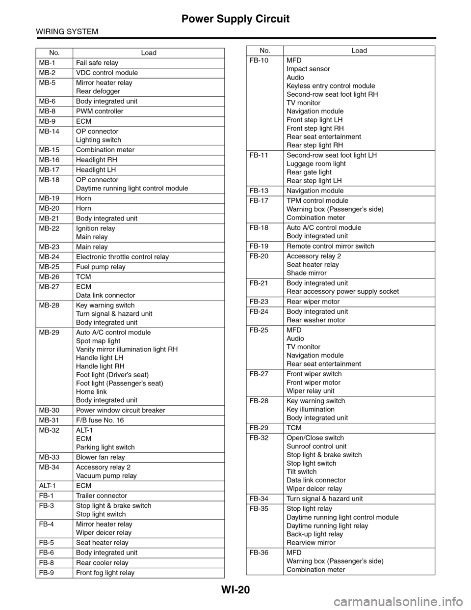
WI-20
Power Supply Circuit
WIRING SYSTEM
No. Load
MB-1 Fail safe relay
MB-2 VDC control module
MB-5 Mirror heater relay
Rear defogger
MB-6 Body integrated unit
MB-8 PWM controller
MB-9 ECM
MB-14 OP connector
Lighting switch
MB-15 Combination meter
MB-16 Headlight RH
MB-17 Headlight LH
MB-18 OP connector
Daytime running light control module
MB-19 Horn
MB-20 Horn
MB-21 Body integrated unit
MB-22 Ignition relay
Main relay
MB-23 Main relay
MB-24 Electronic throttle control relay
MB-25 Fuel pump relay
MB-26 TCM
MB-27 ECM
Data link connector
MB-28 Key warning switch
Tu r n s i g n a l & h a z a r d u n i t
Body integrated unit
MB-29 Auto A/C control module
Spot map light
Va n i t y m i r r o r i l l u m i n a t i o n l i g h t R H
Handle light LH
Handle light RH
Foot light (Driver’s seat)
Foot light (Passenger’s seat)
Home link
Body integrated unit
MB-30 Power window circuit breaker
MB-31 F/B fuse No. 16
MB-32 ALT-1
ECM
Par king light switch
MB-33 Blower fan relay
MB-34 Accessory relay 2
Va c u u m p u m p r e l ay
ALT-1 ECM
FB-1 Trailer connector
FB-3 Stop light & brake switch
Stop light switch
FB-4 Mirror heater relay
Wiper deicer relay
FB-5 Seat heater relay
FB-6 Body integrated unit
FB-8 Rear cooler relay
FB-9 Front fog light relay
FB-10 MFD
Impact sensor
Audio
Keyless entr y control module
Second-row seat foot light RH
TV monitor
Navigation module
Fr o n t s te p li gh t LH
Fr o n t s te p li gh t RH
Rear seat entertainment
Rear step light RH
FB-11 Second-row seat foot light LH
Luggage room light
Rear gate light
Rear step light LH
FB-13 Navigation module
FB-17 TPM control module
War ning box (Passenger’s side)
Combination meter
FB-18 Auto A/C control module
Body integrated unit
FB-19 Remote control mirror switch
FB-20 Accessory relay 2
Seat heater relay
Shade mirror
FB-21 Body integrated unit
Rear accessory power supply socket
FB-23 Rear wiper motor
FB-24 Body integrated unit
Rear washer motor
FB-25 MFD
Audio
TV monitor
Navigation module
Rear seat entertainment
FB-27 Front wiper switch
Fr o n t wi p er mo t or
Wiper relay unit
FB-28 Key warning switch
Key illumination
Body integrated unit
FB-29 TCM
FB-32 Open/Close switch
Sunroof control unit
Stop light & brake switch
Stop light switch
Tilt switch
Data link connector
Wiper deicer relay
FB-34 Turn signal & hazard unit
FB-35 Stop light relay
Daytime running light control module
Daytime running light relay
Back-up light relay
Rearview mirror
FB-36 MFD
War ning box (Passenger’s side)
Combination meter
No. Load
Page 2374 of 2453
WI-90
Back–up Light System
WIRING SYSTEM
25.Back–up Light System
A: WIRING DIAGRAM
WI-08096
BACK/L-01BACK/L-01
FB-35F/B FUSE NO. 18(IG)
TOPOWER SUPPLYCIRCUIT
B11
BrR
B55B:
GL
TCM
1 BrY
R57
B90
R50
REARVIEWMIRROR
BrY
6
BrYR2
B97
BrY
BrY
5
B
BACK-UPLIGHTLH
D91
2
BrY
B
1
BACK-UPLIGHTRH
2
BrY
1
6
BrYB228
OPCONNECTOR
B
D87
123410 11 1219 20 21135614 1578916 17 1822 23 24
123456789101112
B356
34
12D91
12
B55B:
D87
(GRAY)
R38
R224
R225
D33
B228
131415
123456789101112
R247R215
2
B
B
R37
D34
REF. TO GROUNDCIRCUIT [GND-06]
R50
123456789101112
GL
1
GL
4
2
BrR
3
BrY
BACK-UPLIGHT RELAY
B356
BrY
BrY
JOINTCONNECTOR
R224
R2251*
2*
BrY
BrY
BrY
THROUGHJOINTCONNECTOR
D33
R38
BrY
BrY
3
10
87
: TERMINAL NO. OPTIONAL ARRANGEMENT BETWEEN 7 AND 8
: TERMINAL NO. OPTIONAL ARRANGEMENT BETWEEN 11 AND 12
1*
2*
R57
321
R215
12
10115634897131412
D34
121
B97
1234567891011 121316 17 18 19 201415
(GRAY)
(GRAY)
Page 2445 of 2453

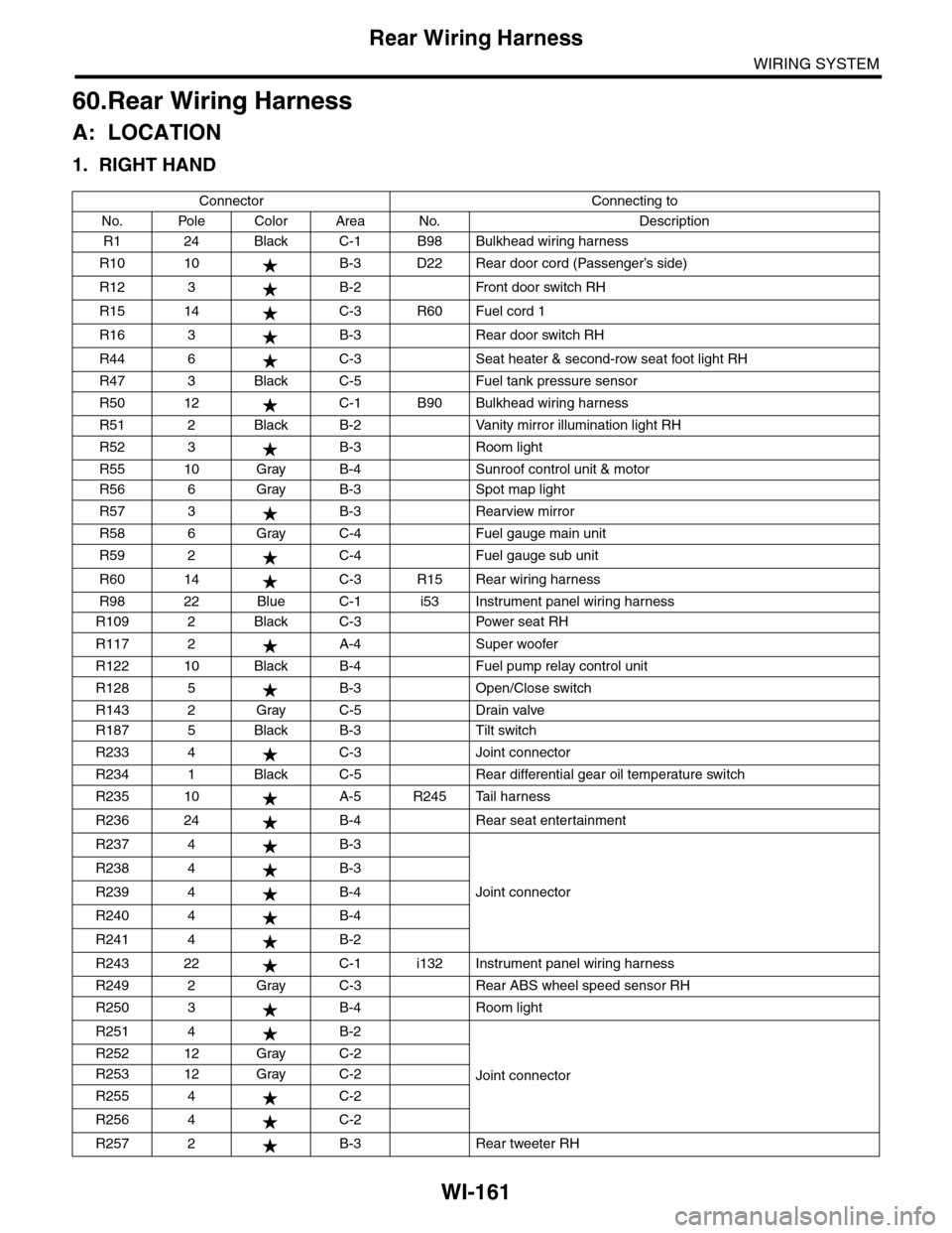
WI-161
Rear Wiring Harness
WIRING SYSTEM
60.Rear Wiring Harness
A: LOCATION
1. RIGHT HAND
Connector Connecting to
No. Pole Color Area No. Description
R1 24 Black C-1 B98 Bulkhead wiring harness
R10 10 B-3 D22 Rear door cord (Passenger’s side)
R12 3 B-2 Front door switch RH
R15 14 C-3 R60 Fuel cord 1
R16 3 B-3 Rear door switch RH
R44 6 C-3 Seat heater & second-row seat foot light RH
R47 3 Black C-5 Fuel tank pressure sensor
R50 12 C-1 B90 Bulkhead wiring harness
R51 2 Black B-2 Vanity mirror illumination light RH
R52 3 B-3 Room light
R55 10 Gray B-4 Sunroof control unit & motor
R56 6 Gray B-3 Spot map light
R57 3 B-3 Rearview mirror
R58 6 Gray C-4 Fuel gauge main unit
R59 2 C-4 Fuel gauge sub unit
R60 14 C-3 R15 Rear wiring harness
R98 22 Blue C-1 i53 Instrument panel wiring harness
R109 2 Black C-3 Power seat RH
R117 2 A-4 Super woofer
R122 10 Black B-4 Fuel pump relay control unit
R128 5 B-3 Open/Close switch
R143 2 Gray C-5 Drain valve
R187 5 Black B-3 Tilt switch
R233 4 C-3 Joint connector
R234 1 Black C-5 Rear differential gear oil temperature switch
R235 10 A-5 R245 Tail harness
R236 24 B-4 Rear seat entertainment
R237 4 B-3
Joint connector
R238 4 B-3
R239 4 B-4
R240 4 B-4
R241 4 B-2
R243 22 C-1 i132 Instrument panel wiring harness
R249 2 Gray C-3 Rear ABS wheel speed sensor RH
R250 3 B-4 Room light
R251 4 B-2
Joint connector
R252 12 Gray C-2
R253 12 Gray C-2
R255 4 C-2
R256 4 C-2
R257 2 B-3 Rear tweeter RH