2009 SUBARU TRIBECA change wheel
[x] Cancel search: change wheelPage 744 of 2453

BR-30
Brake Fluid
BRAKE
10.Brake Fluid
A: INSPECTION
1) Check that the brake fluid level is between “MIN”
and “MAX”. If out of the specified range, refill or
drain fluid. If the fluid level is close to “MIN”, check
the brake pad for wear and refill the fluid.
2) Check the fluid for discoloration. If the fluid color
has changed excessively, drain the fluid and refill
with new fluid.
B: REPLACEMENT
CAUTION:
•Do not let brake fluid come into contact with
the painted surface of the vehicle body. Wash
away with water immediately and wipe off if it is
spilled by accident.
•Avoid mixing brake fluids of different brands
to prevent fluid performance from degrading.
•Be careful not to allow dirt or dust to enter the
reservoir tank.
NOTE:
•During the operation, keep the reservoir tank
filled with brake fluid to eliminate entry of air.
•Operate the brake pedal slowly.
•For convenience and safety, perform work with 2
people.
•The required amount of brake fluid is approxi-
mately 600 m2 (20 US fl oz, 21 Imp fl oz) for entire
brake system.
1) Lift-up the vehicle and set rigid racks at the spec-
ified locations, or keep the vehicle lifted.
2) Remove both the front and rear wheels.
3) Drain brake fluid from the reservoir tank.
4) Refill the reservoir tank with the recommended
brake fluid.
Recommended brake fluid:
Refer to the specification.
Perform the same procedure as for bleeding the
brake line, until new brake fluid comes out from vi-
nyl tube.
NOTE:
Perform the brake fluid replacement starting in or-
der from the farthest wheel cylinder from the mas-
ter cylinder.
Page 856 of 2453

FS-8
Wheel Alignment
FRONT SUSPENSION
2. CAMBER
•INSPECTION
1) Place the front wheel on the turning radius
gauge. Make sure the ground contact surfaces of
front and rear wheels are at the same height.
2) Set the adapter at the center of wheel, and then
attach the wheel alignment gauge.
3) Measure the camber angle in accordance with
the operation manual for wheel alignment gauge.
•FRONT CAMBER ADJUSTMENT
1) When adjusting the camber, adjust it to the fol-
lowing value.
2) Loosen the two self–locking nuts located at the
lower front section of the strut.
NOTE:
When the adjusting bolt needs to be loosened or
tightened, hold its head with a wrench and turn the
self–locking nut.
3) Turn the camber adjusting bolt so that the cam-
ber is set at specification.
NOTE:
Moving the adjusting bolt by one scale changes the
camber by approximately 0°15′.
(1) Alignment gauge
(2) Turning radius gauge
(3) Adapter
Camber (Difference between RH and LH 45′ or less)
0°00′±0°45′
Camber (Difference between RH and LH 45′ or less)
0°00′±0°30′
FS-00213
(1)
(2)
(3)
(1) Strut
(2) Adjusting bolt
(3) Housing
(4) Outer
(5) Inner
(6) Camber is increased.
(7) Camber is decreased.
(1)
(4)
(6) (7)
(2)
(3)
(5)
FS-00196
Page 860 of 2453
FS-12
Wheel Alignment
FRONT SUSPENSION
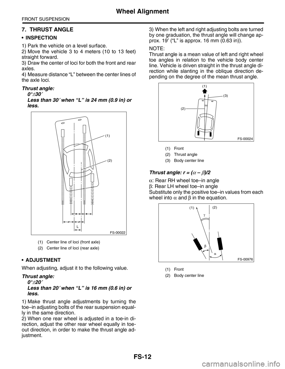
7. THRUST ANGLE
•INSPECTION
1) Park the vehicle on a level surface.
2) Move the vehicle 3 to 4 meters (10 to 13 feet)
straight forward.
3) Draw the center of loci for both the front and rear
axles.
4) Measure distance “L” between the center lines of
the axle loci.
Thrust angle:
0°±30′
Less than 30′ when “L” is 24 mm (0.9 in) or
less.
•ADJUSTMENT
When adjusting, adjust it to the following value.
Thrust angle:
0°±20′
Less than 20′ when “L” is 16 mm (0.6 in) or
less.
1) Make thrust angle adjustments by turning the
toe–in adjusting bolts of the rear suspension equal-
ly in the same direction.
2) When one rear wheel is adjusted in a toe-in di-
rection, adjust the other rear wheel equally in toe-
out direction, in order to make the thrust angle ad-
justment.
3) When the left and right adjusting bolts are turned
by one graduation, the thrust angle will change ap-
prox. 19′ (“L” is approx. 16 mm (0.63 in)).
NOTE:
Thrust angle is a mean value of left and right wheel
toe angles in relation to the vehicle body center
line. Vehicle is driven straight in the thrust angle di-
rection while slanting in the oblique direction de-
pending on the degree of the mean thrust angle.
Thrust angle: r = (α – β)/2
α: Rear RH wheel toe–in angle
β: Rear LH wheel toe–in angle
Substitute only the positive toe–in values from each
wheel into α and β in the equation.
(1) Center line of loci (front axle)
(2) Center line of loci (rear axle)
(1)
(2)
L
FS-00022
(1) Front
(2) Thrust angle
(3) Body center line
(1) Front
(2) Body center line
FS-00024
(2)
(3)
(1)
FS-00976
(1)(2)
Page 928 of 2453

PS-48
Power Steering Fluid
POWER ASSISTED SYSTEM (POWER STEERING)
9. Power Steering Fluid
A: SPECIFICATION
B: INSPECTION
1) Check the power steering fluid for deterioration
or contamination. If the fluid is highly deteriorated
or contaminated, drain it and refill with new fluid.
2) Check the joints and units for oil leakage. If any
oil leaks are found, repair or replace the applicable
part.
3) Inspect the fluid level of reservoir tank with vehi-
cle on level surface and engine stopped.
If the level is at “MIN. ” point or below, add fluid to
keep the level in the specified range of the indica-
tor. If at “MAX. ” point or above, drain fluid by using
a syringe or the like.
(1) Check at power steering fluid temperature
20°C (68°F); read the fluid level on the “COLD”
side.
(2) Check at power steering fluid temperature
80°C (176°F); read the fluid level on the “HOT”
side.
C: REPLACEMENT
1) Lift-up the vehicle.
2) Remove the crossmember support.
3) Remove the pipe joint in the center of gearbox,
and connect the vinyl hose to the pipe and joint.
Wipe fluid off while turning the steering wheel.
4) Add the specified fluid to reservoir tank at “MAX”
level.
5) Continue to turn the steering wheel slowly from
lock to lock until the bubbles stop appearing on oil
surface while keeping the fluid at the level in the
Step 4).
6) If the steering wheel is turned in a low fluid level
condition, air will be sucked into the pipe. If sucked,
leave it about half an hour and then do the step 5)
again.
7) Start the engine and let it idle.
8) Continue to turn the steering wheel slowly from
lock to lock again until the bubbles stop appearing
on oil surface while keeping the fluid at the level in
Step 4).
Normally bubbles will stop appearing after turning
the steering wheel from lock to lock three times.
9) In case bubbles do not stop appearing in the
tank, leave it about half an hour and then do the
step 4) all over again.
10) Lower the vehicle, and then idle the engine.
11) Continue to turn the steering wheel from lock to
lock until the bubbles stop appearing and change of
the fluid level is within 3 mm (0.12 in).
12) In case the following happens, leave it about
half an hour and then do step 8) to 11) again.
(1) The fluid level changes over 3 mm (0.12 in).
(2) Bubbles remain on the upper surface of the
fluid.
(3) Grinding noise is generated from oil pump.
13) Check the fluid leakage after turning steering
wheel from lock to lock with engine running.
Recommended power steering fluid Manufacturer
AT F D E X R O N I I I o r e q u i v a l e n t
B.P.
CALTEX
CASTROL
MOBIL
SHELL
TEXACO
PS-00745
HOT MAXHOT MAINCOLD MAXCOLD MAIN
Page 1036 of 2453
VDC(diag)-44
Diagnostic Procedure with Diagnostic Trouble Code (DTC)
VEHICLE DYNAMICS CONTROL (VDC) (DIAGNOSTICS)
Step Check Yes No
1CHECK THE VDCCM&H/U POWER SUPPLY
CIRCUIT.
1) Turn the ignition switch to OFF.
2) Disconnect the VDCCM&H/U connector.
3) Turn the ignition switch to ON.
4) Measure the voltage between VDCCM&H/
U connector terminals.
Connector & terminal
(B310) No. 1 (+) — (B310) No. 43 (–):
Is the voltage 10 — 15 V? Go to step 2.Check the genera-
tor, batter y and
VDCCM&H/U
power supply cir-
cuit.
2CHECK OUTPUT OF ABS WHEEL SPEED
SENSOR USING SUBARU SELECT MONI-
TOR.
1) Select {Current Data Display & Save} in
Subaru Select Monitor.
2) Read the ABS wheel speed sensor output
corresponding to the faulty wheel in Subaru
Select Monitor data display mode.
Does the speed indicated on
the display change in response
to the speedometer reading
during acceleration/decelera-
tion when the steering wheel is
in the straight-ahead position?
Go to step 3.Go to step 8.
3CHECK POOR CONTACT IN CONNECTOR.
Tu r n t h e i g n i t i o n s w i t c h t o O F F.
Is there poor contact in con-
nectors between VDCCM&H/U
and ABS wheel speed sensor?
Repair the con-
nector.
Go to step 4.
4CHECK CAUSE OF SIGNAL NOISE.
Make sure the radio wave devices and electric
components are installed correctly.
Are the radio wave devices and
electric components installed
correctly?
Go to step 5.Install the radio
wave devices and
electric compo-
nents properly.
5CHECK CAUSE OF SIGNAL NOISE.
Check if the noise sources (such as an
antenna) are installed near the sensor har-
ness.
Are noise sources installed? Install the noise
sources apart from
sensor harness.
Go to step 6.
6CHECK THE VDCCM&H/U.
1) Connect all the connectors.
2) Erase the memory.
3) Perform the inspection mode.
Mode.>
4) Read the DTC.
Is the same DTC displayed? Replace the
VDCCM&H/U.
ule & Hydraulic
Control Unit
(VDCCM&H/U).>
Go to step 7.
7CHECK OTHER DTC DETECTION.Is any other DTC displayed? Perform the diag-
nosis according to
DTC.
It results from a
temporary noise
interference.
8CHECK INSTALLATION OF ABS WHEEL
SPEED SENSOR.
Is the ABS wheel speed sen-
sor installation bolt tightened
7.5 N·m (0.76 kgf-m, 5.5 ft-lb)?
Go to step 9.Tighten the ABS
wheel speed sen-
sor installation
bolts.
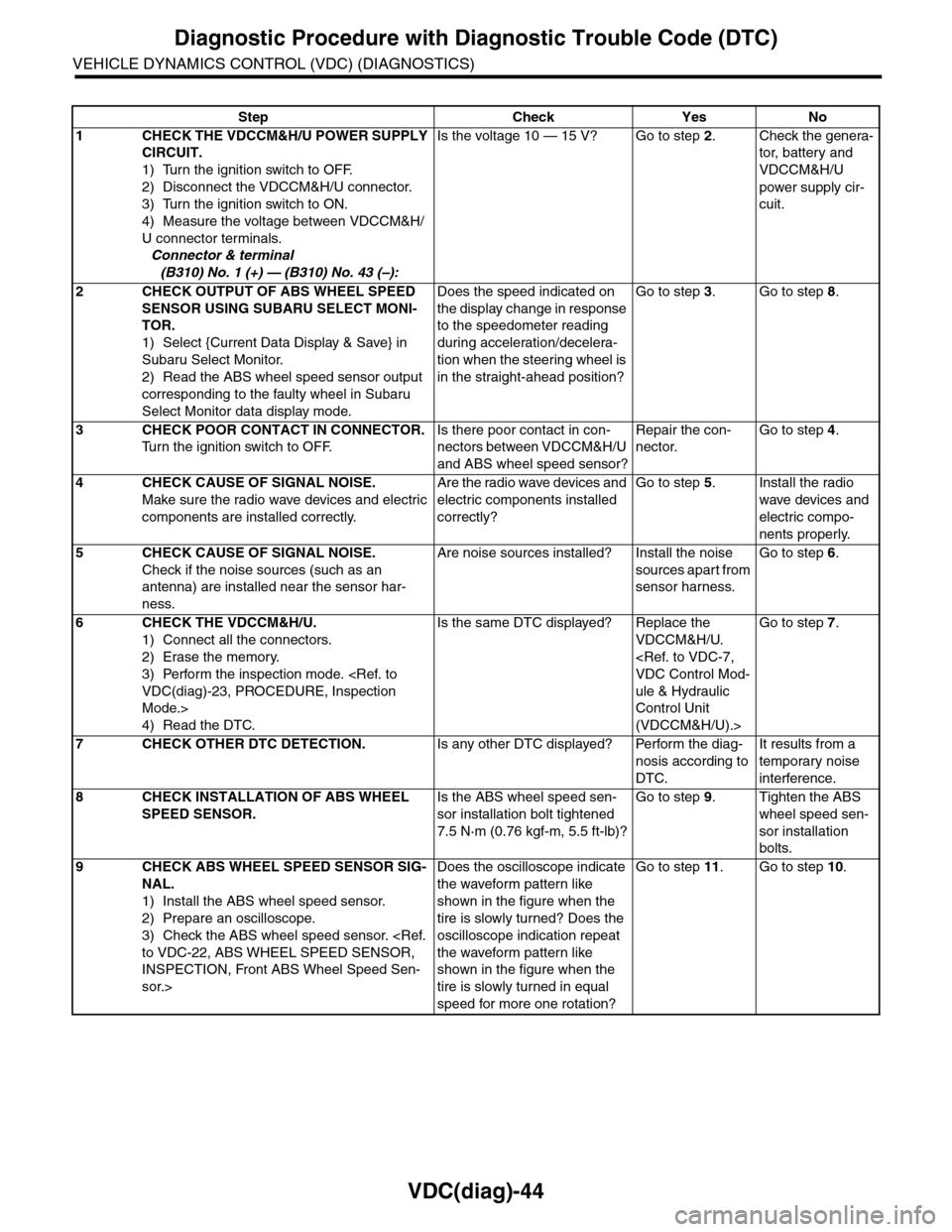
9CHECK ABS WHEEL SPEED SENSOR SIG-
NAL.
1) Install the ABS wheel speed sensor.
2) Prepare an oscilloscope.
3) Check the ABS wheel speed sensor.
INSPECTION, Front ABS Wheel Speed Sen-
sor.>
Does the oscilloscope indicate
the waveform pattern like
shown in the figure when the
tire is slowly turned? Does the
oscilloscope indication repeat
the waveform pattern like
shown in the figure when the
tire is slowly turned in equal
speed for more one rotation?
Go to step 11.Go to step 10.
Page 1102 of 2453
VDC-21
Front ABS Wheel Speed Sensor
VEHICLE DYNAMICS CONTROL (VDC)
7. Front ABS Wheel Speed Sen-
sor
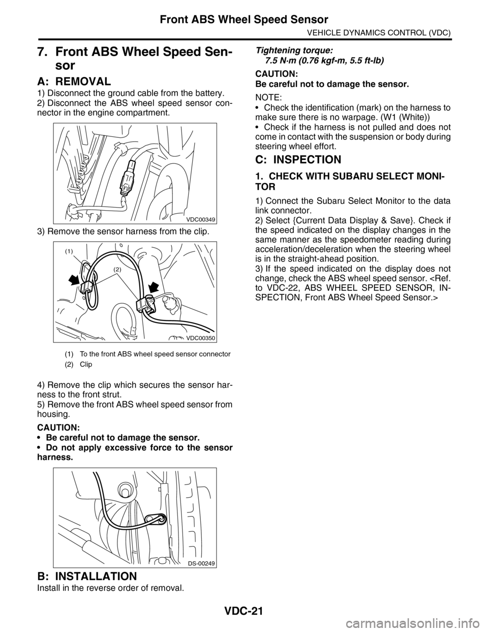
A: REMOVAL
1) Disconnect the ground cable from the battery.
2) Disconnect the ABS wheel speed sensor con-
nector in the engine compartment.
3) Remove the sensor harness from the clip.
4) Remove the clip which secures the sensor har-
ness to the front strut.
5) Remove the front ABS wheel speed sensor from
housing.
CAUTION:
•Be careful not to damage the sensor.
•Do not apply excessive force to the sensor
harness.
B: INSTALLATION
Install in the reverse order of removal.
Tightening torque:
7.5 N·m (0.76 kgf-m, 5.5 ft-lb)
CAUTION:
Be careful not to damage the sensor.
NOTE:
•Check the identification (mark) on the harness to
make sure there is no warpage. (W1 (White))
•Check if the harness is not pulled and does not
come in contact with the suspension or body during
steering wheel effort.
C: INSPECTION
1. CHECK WITH SUBARU SELECT MONI-
TOR
1) Connect the Subaru Select Monitor to the data
link connector.
2) Select {Current Data Display & Save}. Check if
the speed indicated on the display changes in the
same manner as the speedometer reading during
acceleration/deceleration when the steering wheel
is in the straight-ahead position.
3) If the speed indicated on the display does not
change, check the ABS wheel speed sensor.
SPECTION, Front ABS Wheel Speed Sensor.>
(1) To the front ABS wheel speed sensor connector
(2) Clip
VDC00349
VDC00350
(1)
(2)
DS-00249
Page 1112 of 2453
WT-6
Tire
WHEEL AND TIRE SYSTEM
2. Tire
A: INSPECTION
1) Take stones, glass, nails etc. out of the tread
groove.
2) Replace tires in the following cases.
CAUTION:
•When replacing a tire, make sure to use only
tires of the same size, construction and load
range as originally installed.
•Use a tire changer when removing the tire
from the wheel.
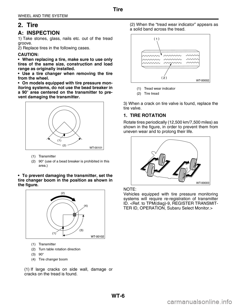
•On models equipped with tire pressure mon-
itoring systems, do not use the bead breaker in
a 90° area centered on the transmitter to pre-
vent damaging the transmitter.
•To prevent damaging the transmitter, set the
tire changer boom in the position as shown in
the figure.
(1) If large cracks on side wall, damage or
cracks on the tread is found.
(2) When the “tread wear indicator” appears as
a solid band across the tread.
3) When a crack on tire valve is found, replace the
tire valve.
1. TIRE ROTATION
Rotate tires periodically (12,500 km/7,500 miles) as
shown in the figure, in order to prevent them from
uneven wear and to prolong their life.
NOTE:
Vehicles equipped with tire pressure monitoring
systems will require re-registration of transmitter
ID.
(1) Transmitter
(2) 90° (use of a bead breaker is prohibited in this
area.)
(1) Transmitter
(2) Turn table rotation direction
(3) 90°
(4) Tire changer boom
(1)
WT-00101(2)
(1) Tread wear indicator
(2) Tire tread
WT-00002
WT-00003
Page 1114 of 2453
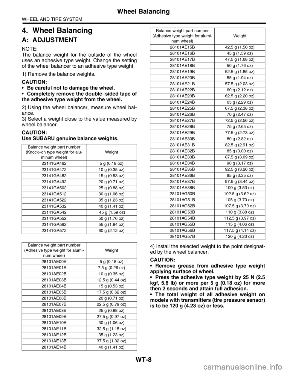
WT-8
Wheel Balancing
WHEEL AND TIRE SYSTEM
4. Wheel Balancing
A: ADJUSTMENT
NOTE:
The balance weight for the outside of the wheel
uses an adhesive type weight. Change the setting
of the wheel balancer to an adhesive type weight.
1) Remove the balance weights.
CAUTION:
•Be careful not to damage the wheel.
•Completely remove the double–sided tape of
the adhesive type weight from the wheel.
2) Using the wheel balancer, measure wheel bal-
ance.
3) Select a weight close to the value measured by
wheel balancer.
CAUTION:
Use SUBARU genuine balance weights.
4) Install the selected weight to the point designat-
ed by the wheel balancer.
CAUTION:
•Remove grease from adhesive type weight
applying surface of wheel.
•Press the adhesive type weight by 25 N (2.5
kgf, 5.6 lb) or more per 5 g (0.18 oz) for more
then 2 seconds and attain full adhesion.
•The total weight of all adhesive weight on
models with transmitters (tire pressure sensor)
is to be 120 g (4.23 oz) or less.
Balance weight par t number
(Knock–on type weight for alu-
minum wheel)
Weight
23141GA462 5 g (0.18 oz)
23141GA472 10 g (0.35 oz)
23141GA482 15 g (0.53 oz)
23141GA492 20 g (0.71 oz)
23141GA502 25 g (0.88 oz)
23141GA512 30 g (1.06 oz)
23141GA522 35 g (1.23 oz)
23141GA532 40 g (1.41 oz)
23141GA542 45 g (1.59 oz)
23141GA552 50 g (1.76 oz)
23141GA562 55 g (1.94 oz)
23141GA572 60 g (2.12 oz)
Balance weight par t number
(Adhesive type weight for alumi-
num wheel)
Weight
28101AE00B 5 g (0.18 oz)
28101AE01B 7.5 g (0.26 oz)
28101AE02B 10 g (0.35 oz)
28101AE03B 12.5 g (0.44 oz)
28101AE04B 15 g (0.53 oz)
28101AE05B 17.5 g (0.62 oz)
28101AE06B 20 g (0.71 oz)
28101AE07B 22.5 g (0.79 oz)
28101AE08B 25 g (0.88 oz)
28101AE09B 27.5 g (0.97 oz)
28101AE10B 30 g (1.06 oz)
28101AE11B 32.5 g (1.15 oz)
28101AE12B 35 g (1.23 oz)
28101AE13B 37.5 g (1.32 oz)
28101AE14B 40 g (1.41 oz)
28101AE15B 42.5 g (1.50 oz)
28101AE16B 45 g (1.59 oz)
28101AE17B 47.5 g (1.68 oz)
28101AE18B 50 g (1.76 oz)
28101AE19B 52.5 g (1.85 oz)
28101AE20B 55 g (1.94 oz)
28101AE21B 57.5 g (2.03 oz)
28101AE22B 60 g (2.12 oz)
28101AE23B 62.5 g (2.20 oz)
28101AE24B 65 g (2.29 oz)
28101AE25B 67.5 g (2.38 oz)
28101AE26B 70 g (2.47 oz)
28101AE27B 72.5 g (2.56 oz)
28101AE28B 75 g (2.65 oz)
28101AE29B 77.5 g (2.73 oz)
28101AE30B 80 g (2.82 oz)
28101AE31B 82.5 g (2.91 oz)
28101AE32B 85 g (3.00 oz)
28101AE33B 87.5 g (3.09 oz)
28101AE34B 90 g (3.17 oz)
28101AE35B 92.5 g (3.26 oz)
28101AE36B 95 g (3.35 oz)
28101AE37B 97.5 g (3.44 oz)
28101AE38B 100 g (3.53 oz)
28101AG50B 102.5 g (3.62 oz)
28101AG51B 105 g (3.70 oz)
28101AG52B 107.5 g (3.79 oz)
28101AG53B 110 g (3.88 oz)
28101AG54B 112.5 g (3.97 oz)
28101AG55B 115 g (4.06 oz)
28101AG56B 117.5 g (4.14 oz)
28101AG57B 120 g (4.23 oz)
Balance weight part number
(Adhesive type weight for alumi-
num wheel)
Weight