2009 SUBARU TRIBECA service
[x] Cancel search: servicePage 3 of 2453
AB-4
General Description
AIRBAG SYSTEM
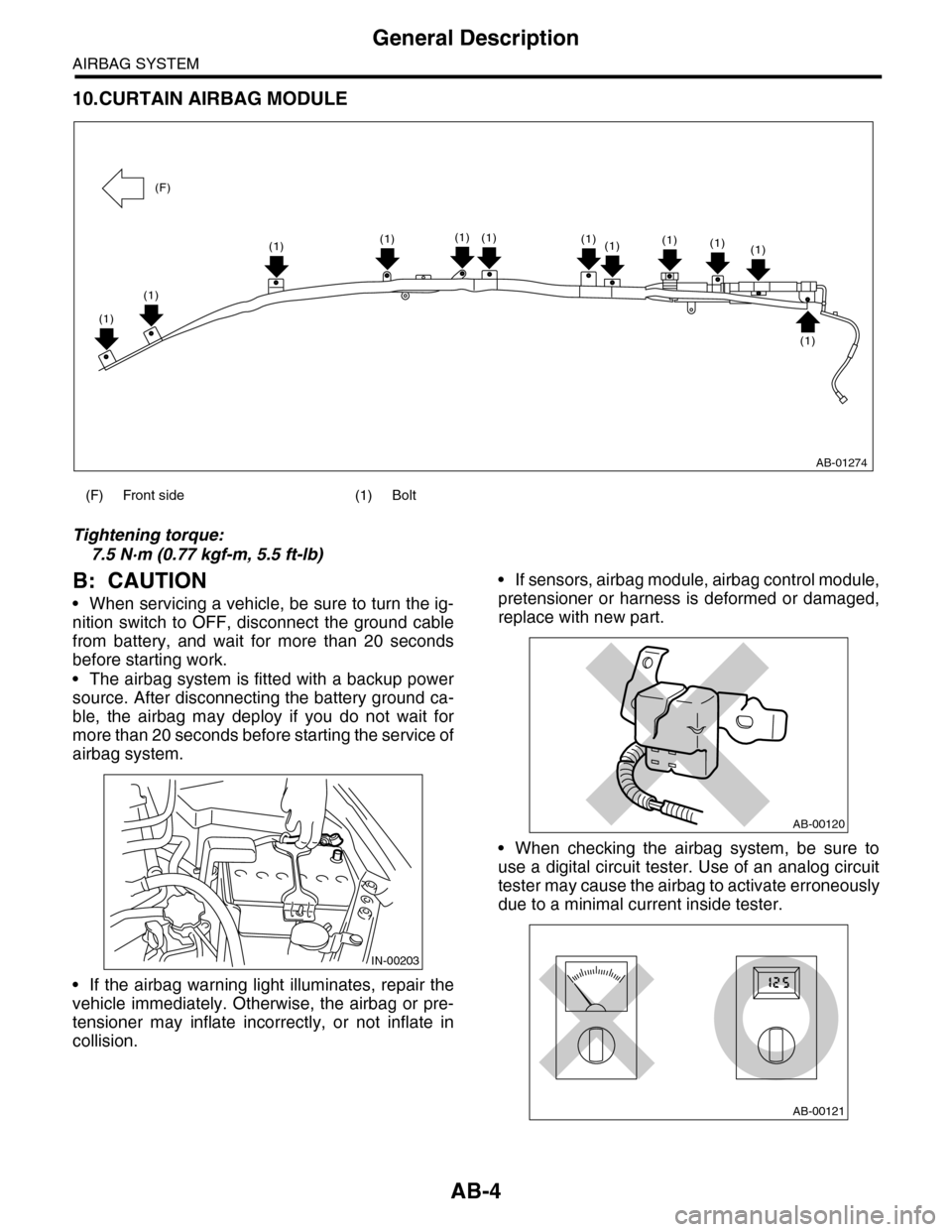
10.CURTAIN AIRBAG MODULE
Tightening torque:
7.5 N·m (0.77 kgf-m, 5.5 ft-lb)
B: CAUTION
•When servicing a vehicle, be sure to turn the ig-
nition switch to OFF, disconnect the ground cable
from battery, and wait for more than 20 seconds
before starting work.
•The airbag system is fitted with a backup power
source. After disconnecting the battery ground ca-
ble, the airbag may deploy if you do not wait for
more than 20 seconds before starting the service of
airbag system.
•If the airbag warning light illuminates, repair the
vehicle immediately. Otherwise, the airbag or pre-
tensioner may inflate incorrectly, or not inflate in
collision.
•If sensors, airbag module, airbag control module,
pretensioner or harness is deformed or damaged,
replace with new part.
•When checking the airbag system, be sure to
use a digital circuit tester. Use of an analog circuit
tester may cause the airbag to activate erroneously
due to a minimal current inside tester.
(F) Front side (1) Bolt
AB-01274
(1)(1)
(1)
(1)(1)(1)(1)(1)(1)(1)
(1)
(1)
(F)
IN-00203
AB-00120
AB-00121
Page 28 of 2453

AB(diag)-4
General Description
AIRBAG SYSTEM (DIAGNOSTICS)
3. General Description
A: CAUTION
•When servicing a vehicle, be sure to turn the ig-
nition switch to OFF, disconnect the ground cable
from battery, and wait for more than 20 seconds
before starting work.
•The airbag system is fitted with a backup power
source. After disconnecting the battery ground ca-
ble, the airbag may deploy if you do not wait for
more than 20 seconds before starting the service of
airbag system.
•If sensors, airbag module, airbag control module,
pretensioner or harness is deformed or damaged,
replace with new part.
•Do not use the airbag system and pretensioners
on other vehicles. When replacing parts, be sure to
replace them with new ones.
•When checking the airbag system, be sure to
use a digital circuit tester. Use of an analog circuit
tester may cause the airbag to activate erroneously
due to a minimal current inside tester.
•When checking, use a test harness (1). Damage
to connector terminal causes malfunction. Do not
directly put the tester probe on airbag connector
terminal.
•Do not drop the airbag system parts, or keep
them at high temperature over 93°C (199°F), or let
water, oil or grease get on them; the internal parts
may be damaged and reliability greatly lowered.
IN-00203
AB-00120
AB-00121
AB-00122
(1)
AB-00123
Page 217 of 2453
ET-32
Steering Satellite Switch
ENTERTAINMENT
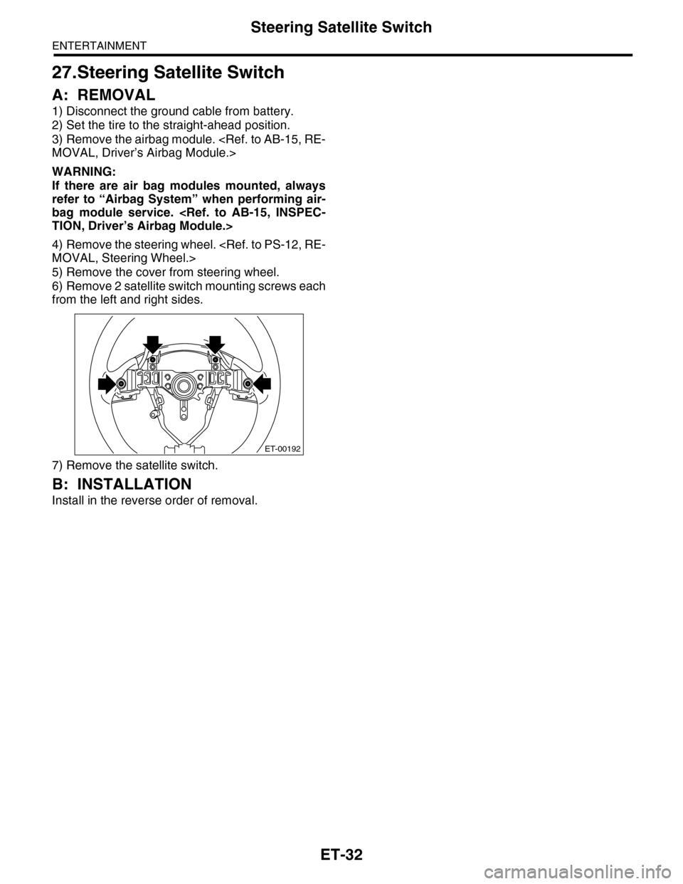
27.Steering Satellite Switch
A: REMOVAL
1) Disconnect the ground cable from battery.
2) Set the tire to the straight-ahead position.
3) Remove the airbag module.
WARNING:
If there are air bag modules mounted, always
refer to “Airbag System” when performing air-
bag module service.
4) Remove the steering wheel.
5) Remove the cover from steering wheel.
6) Remove 2 satellite switch mounting screws each
from the left and right sides.
7) Remove the satellite switch.
B: INSTALLATION
Install in the reverse order of removal.
ET-00192
Page 304 of 2453
GW-9
Front Door Glass
GLASS/WINDOWS/MIRRORS
4. Front Door Glass
A: REMOVAL
1) Remove the front door trim.
2) Remove the sealing cover.
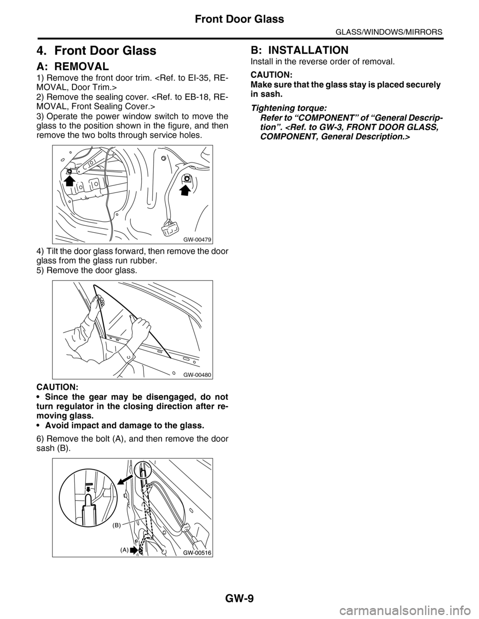
3) Operate the power window switch to move the
glass to the position shown in the figure, and then
remove the two bolts through service holes.
4) Tilt the door glass forward, then remove the door
glass from the glass run rubber.
5) Remove the door glass.
CAUTION:
•Since the gear may be disengaged, do not
turn regulator in the closing direction after re-
moving glass.
•Avoid impact and damage to the glass.
6) Remove the bolt (A), and then remove the door
sash (B).
B: INSTALLATION
Install in the reverse order of removal.
CAUTION:
Make sure that the glass stay is placed securely
in sash.
Tightening torque:
Refer to “COMPONENT” of “General Descrip-
tion”.
GW-00479
GW-00480
Page 311 of 2453

GW-16
Rear Door Glass
GLASS/WINDOWS/MIRRORS
11.Rear Door Glass
A: REMOVAL
1) Remove the rear door trim.
2) Remove the sealing cover.
3) Apply the protective tape (1) to the areas as
shown in the figure.
4) Operate the power window switch to move the
glass to the position shown in the figure, and then
remove the two bolts through service holes.
5) Remove the sash retaining bolts (A), and loosen
the retaining nuts (B).
6) Move the sash (C) upward, and move the nut (B)
to the position on rear door as shown in the figure.
7) Detach the rear part of door glass from sash (1),
and move it backward (2). Tilt the door glass in-
ward, and move it upward to remove (3).
CAUTION:
•Since the gear may be disengaged, do not
turn regulator in the closing direction after re-
moving glass.
•Avoid impact and damage to the glass.
8) Remove the glass run rubber.
9) Remove the door sash.
B: INSTALLATION
Install in the reverse order of removal.
CAUTION:
Make sure that the glass run rubber is placed
securely in door frame and sash.
Tightening torque:
Refer to “COMPONENT” of “General Descrip-
tion”.
GW-00487
(1)
GW-00488
GW-00491
(B)
(A)
GW-00489
(C)
(B)
GW-00490
(1)
(2)
(3)
Page 340 of 2453

AC-14
General Description
HVAC SYSTEM (HEATER, VENTILATOR AND A/C)
C: CAUTION
1. HFC-134A A/C SYSTEM
•The cooling system components for the HFC-
134a system such as the refrigerant and compres-
sor oil are different from the conventional CFC-12
system components and they are incompatible with
each other.
•Vehicles with the HFC-134a system can be iden-
tified by the label (A) attached to the vehicle.
Before maintenance, check which A/C system is in-
stalled to the vehicle.
2. COMPRESSOR OIL
•HFC-134a compressor oil has no compatibility
with that of CFC-12 system.
•Use only Denso Oil 8, the manufacturer-autho-
rized compressor oil for the HFC-134a system.
•Do not mix multiple compressor oils.
If CFC-12 compressor oil is used in the HFC-134a
A/C system, the compressor may become stuck
due to poor lubrication, or the refrigerant may leak
due to swelling of rubber parts.
On the other hand, if HFC-134a compressor oil is
used in a CFC-12 A/C system, the durability of the
A/C system will be lowered.
•HFC-134a compressor oil is very hygroscopic.
When replacing or installing/removing A/C parts,
immediately isolate the oil from atmosphere using a
plug or tape. In order to avoid moisture, store the oil
in a container with its cap tightly closed.
3. REFRIGERANT
•CFC-12 refrigerant cannot be used in a HFC-
134a A/C system. HFC-134a refrigerant, also can-
not be used in a CFC-12 A/C system.
•If an incorrect or no refrigerant is used, it will re-
sult in poor lubrication and the compressor itself
may be damaged.
4. HANDLING OF REFRIGERANT
•The refrigerant boils at approx. –30°C (22°F).
When handling it, be sure to wear protective gog-
gles and protective gloves. Direct contact of the re-
frigerant with skin may cause frostbite.
If the refrigerant gets into your eye, avoid rubbing
your eyes with your hands. Wash your eye with
plenty of water, and receive medical treatment from
an eye doctor.
•Do not heat a service can. If a service can is di-
rectly heated, or put into boiling water, the inside
pressure will become extremely high. This may
cause the can to explode. If a service can must be
warmed up, use warm water of 40°C (104°F) or less.
•Do not drop or subject a service can to impacts.
(Observe the precautions and operation procedure
described on the refrigerant can.)
•When the engine is running, do not open the
high-pressure valve of the manifold gauge. High-
pressure gas can back-flow resulting in an explo-
sion of the can.
•Provide good ventilation and do not work in a
closed area.
•In order to prevent global warming, avoid releas-
ing HFC-134a into the atmosphere. Using a refrig-
erant recovery system, discharge and recycle the
gas.
AC-01380
(A) Goggles
(B) Gloves
(C) Avoid open flame
(D) No direct heat on container
(E) Do not discharge
(F) Loosen
(A)(B)
(C) (D)
(E)
(F)
AC-00007
Page 341 of 2453
AC-15
General Description
HVAC SYSTEM (HEATER, VENTILATOR AND A/C)
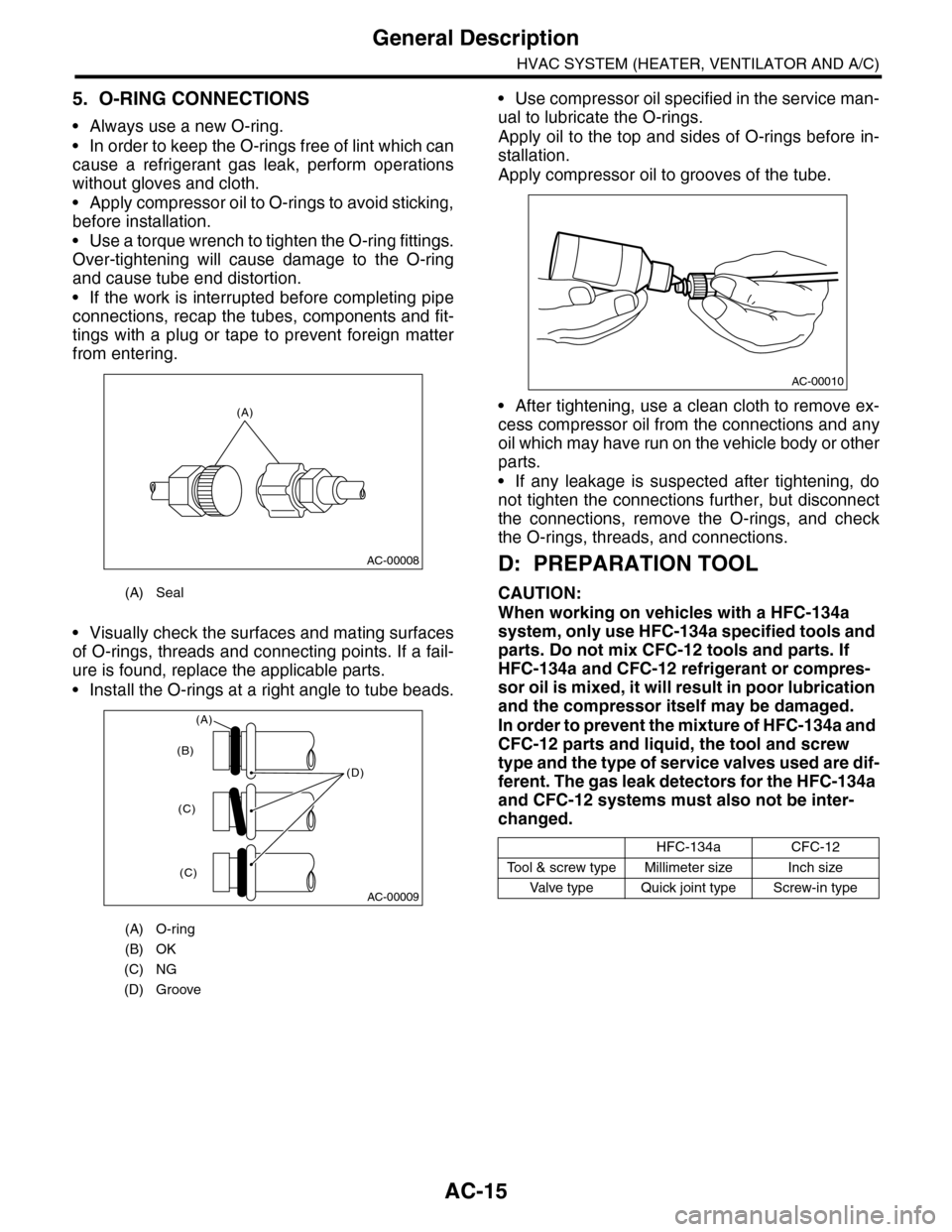
5. O-RING CONNECTIONS
•Always use a new O-ring.
•In order to keep the O-rings free of lint which can
cause a refrigerant gas leak, perform operations
without gloves and cloth.
•Apply compressor oil to O-rings to avoid sticking,
before installation.
•Use a torque wrench to tighten the O-ring fittings.
Over-tightening will cause damage to the O-ring
and cause tube end distortion.
•If the work is interrupted before completing pipe
connections, recap the tubes, components and fit-
tings with a plug or tape to prevent foreign matter
from entering.
•Visually check the surfaces and mating surfaces
of O-rings, threads and connecting points. If a fail-
ure is found, replace the applicable parts.
•Install the O-rings at a right angle to tube beads.
•Use compressor oil specified in the service man-
ual to lubricate the O-rings.
Apply oil to the top and sides of O-rings before in-
stallation.
Apply compressor oil to grooves of the tube.
•After tightening, use a clean cloth to remove ex-
cess compressor oil from the connections and any
oil which may have run on the vehicle body or other
parts.
•If any leakage is suspected after tightening, do
not tighten the connections further, but disconnect
the connections, remove the O-rings, and check
the O-rings, threads, and connections.
D: PREPARATION TOOL
CAUTION:
When working on vehicles with a HFC-134a
system, only use HFC-134a specified tools and
parts. Do not mix CFC-12 tools and parts. If
HFC-134a and CFC-12 refrigerant or compres-
sor oil is mixed, it will result in poor lubrication
and the compressor itself may be damaged.
In order to prevent the mixture of HFC-134a and
CFC-12 parts and liquid, the tool and screw
type and the type of service valves used are dif-
ferent. The gas leak detectors for the HFC-134a
and CFC-12 systems must also not be inter-
changed.
(A) Seal
(A) O-ring
(B) OK
(C) NG
(D) Groove
(A)
AC-00008
AC-00009
(D)
(B)
(C)
(C)
(A)
HFC-134aCFC-12
To o l & s c r e w t y p e M i l l i m e t e r s i z e I n c h s i z e
Va l ve t y p e Q u i ck j o i n t t y p e S c r ew - i n t y p e
AC-00010
Page 342 of 2453
AC-16
General Description
HVAC SYSTEM (HEATER, VENTILATOR AND A/C)
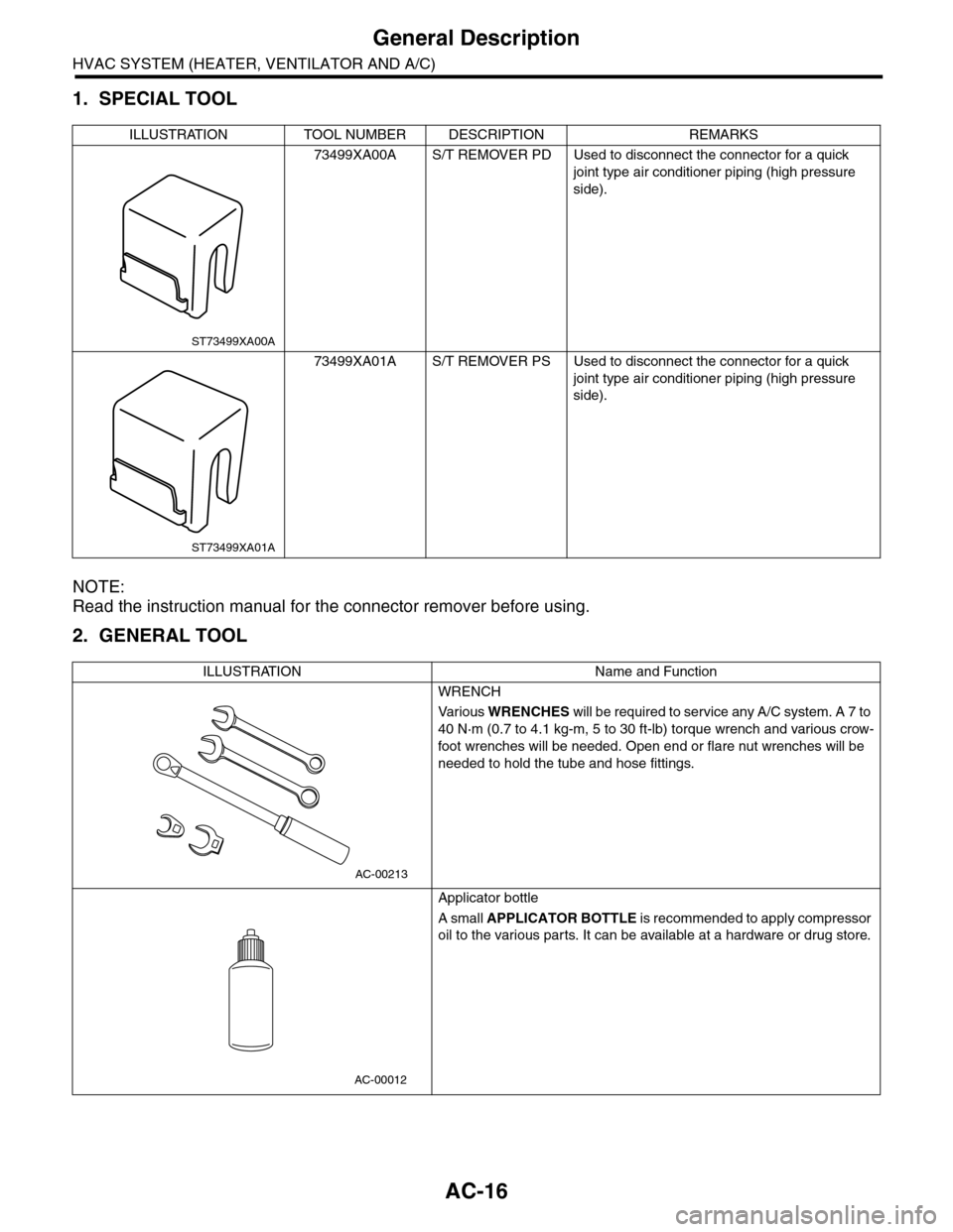
1. SPECIAL TOOL
NOTE:
Read the instruction manual for the connector remover before using.
2. GENERAL TOOL
ILLUSTRATION TOOL NUMBER DESCRIPTION REMARKS
73499XA00A S/T REMOVER PD Used to disconnect the connector for a quick
joint type air conditioner piping (high pressure
side).
73499XA01A S/T REMOVER PS Used to disconnect the connector for a quick
joint type air conditioner piping (high pressure
side).
ILLUSTRATION Name and Function
WRENCH
Va r i o u s WRENCHES will be required to service any A/C system. A 7 to
40 N·m (0.7 to 4.1 kg-m, 5 to 30 ft-lb) torque wrench and various crow-
foot wrenches will be needed. Open end or flare nut wrenches will be
needed to hold the tube and hose fittings.
Applicator bottle
A small APPLICATOR BOTTLE i s r e c om me nd e d to a p pl y co mp r e ss or
oil to the various parts. It can be available at a hardware or drug store.
ST73499XA00A
ST73499XA01A
AC-00213
AC-00012