Page 1132 of 2453
CO(H6DO)-13
Water Pump
COOLING
4. Water Pump
A: REMOVAL
1) Remove the radiator.
REMOVAL, Radiator.>
2) Remove the V-belts.
3) Remove the front chain cover.
Cover.>
4) Remove the timing chain assembly.
Assembly.>
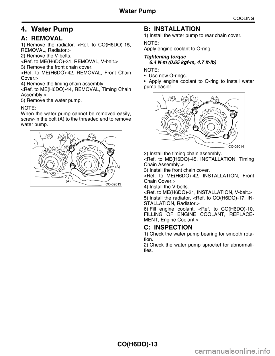
5) Remove the water pump.
NOTE:
When the water pump cannot be removed easily,
screw-in the bolt (A) to the threaded end to remove
water pump.
B: INSTALLATION
1) Install the water pump to rear chain cover.
NOTE:
Apply engine coolant to O-ring.
Tightening torque
6.4 N·m (0.65 kgf-m, 4.7 ft-lb)
NOTE:
•Use new O-rings.
•Apply engine coolant to O-ring to install water
pump easier.
2) Install the timing chain assembly.
Chain Assembly.>
3) Install the front chain cover.
Chain Cover.>
4) Install the V-belts.
5) Install the radiator.
STALLATION, Radiator.>
6) Fill engine coolant.
FILLING OF ENGINE COOLANT, REPLACE-
MENT, Engine Coolant.>
C: INSPECTION
1) Check the water pump bearing for smooth rota-
tion.
2) Check the water pump sprocket for abnormali-
ties.
CO-02013
(A)
(A)
CO-02014
Page 1858 of 2453
LU(H6DO)-9
Oil Pump
LUBRICATION
C: INSPECTION
1. TIP CLEARANCE
Measure the tip clearance of rotors. If the clearance
exceeds specification, replace the rotors as a
matched set.
Tip clearance:
Specification
0.04 — 0.14 mm (0.0016 — 0.0055 in)
2. CASE CLEARANCE
Measure the clearance between the outer rotor and
rear chain cover rotor housing. If the clearance ex-
ceeds the standard value, replace the outer rotor.
Case clearance:
Specification
0.110 — 0.175 mm (0.0043 — 0.0069 in)
3. SIDE CLEARANCE
Measure the clearance between oil pump inner ro-
tor and rear chain cover. If the clearance exceeds
specification, replace the rotors as a matched set.
Side clearance:
Specification
0.020 — 0.046 mm (0.0008 — 0.0018 in)
4. OIL PUMP CASE
Check the worn shaft hole, clogged oil passage,
crank and other parts for faults.
LU-02014
LU-02015
LU-02016
Page 1859 of 2453
LU(H6DO)-10
Oil Pump Relief Valve
LUBRICATION
5. Oil Pump Relief Valve
A: REMOVAL
1. REAR CHAIN COVER SIDE
Oil pump relief valve is integrated into oil pump cov-
er as one unit; therefore, refer to “Oil Pump” for re-
moval procedure.
REMOVAL, Oil Pump.>
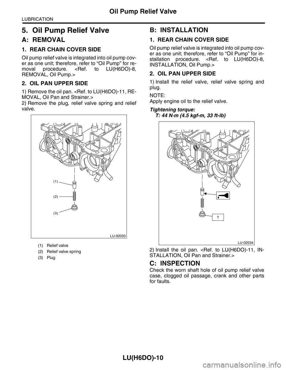
2. OIL PAN UPPER SIDE
1) Remove the oil pan.
MOVAL, Oil Pan and Strainer.>
2) Remove the plug, relief valve spring and relief
valve.
B: INSTALLATION
1. REAR CHAIN COVER SIDE
Oil pump relief valve is integrated into oil pump cov-
er as one unit; therefore, refer to “Oil Pump” for in-
stallation procedure.
INSTALLATION, Oil Pump.>
2. OIL PAN UPPER SIDE
1) Install the relief valve, relief valve spring and
plug.
NOTE:
Apply engine oil to the relief valve.
Tightening torque:
T: 44 N·m (4.5 kgf-m, 33 ft-lb)
2) Install the oil pan.
STALLATION, Oil Pan and Strainer.>
C: INSPECTION
Check the worn shaft hole of oil pump relief valve
case, clogged oil passage, crank and other parts
for faults.
(1) Relief valve
(2) Relief valve spring
(3) Plug
(1)
LU-02033
(2)
(3)
LU-02034
T
Page 1872 of 2453
ME(H6DO)-6
General Description
MECHANICAL
2. TIMING CHAIN COVER
(1) Crank pulley coverTightening torque: N·m (kgf-m, ft-lb)
(2) O-ringT1:
Pulley.>(3) Crank pulley
(4) Sealing washerT2:
Chain Cover.>(5) Oil seal
(6) Front chain cover T3:
Chain Cover.>(7) Rear chain cover
(8) Water pump gasket T4: 6.4 (0.65, 4.7)
ME-02021
T2
T2
T2
T2
T3T3
T3
T3
T3
(4)
(6)
(7)
(8)
(5)
T1
T4
(1)
(3)
(2)
Page 1875 of 2453
ME(H6DO)-9
General Description
MECHANICAL
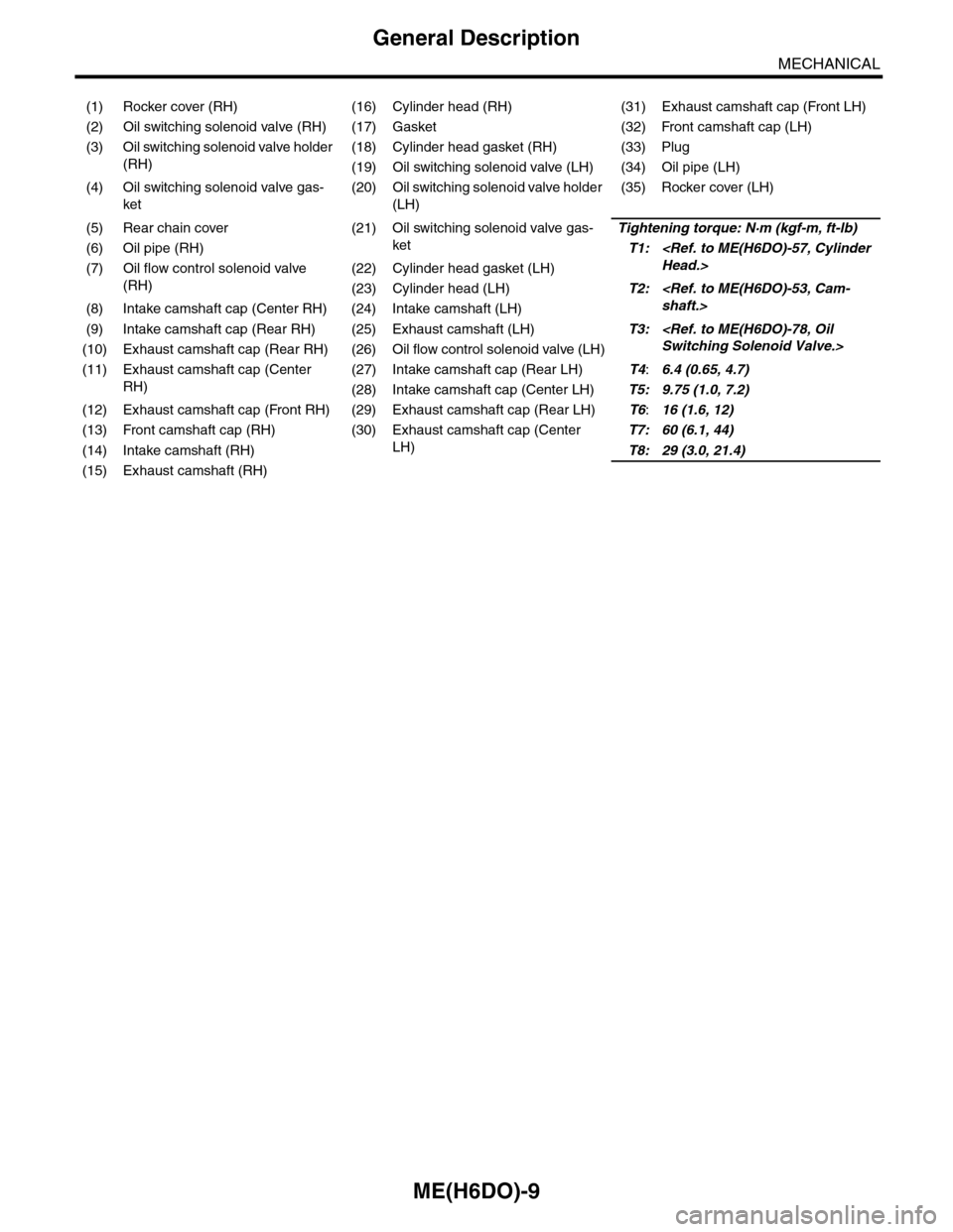
(1) Rocker cover (RH) (16) Cylinder head (RH) (31) Exhaust camshaft cap (Front LH)
(2) Oil switching solenoid valve (RH) (17) Gasket (32) Front camshaft cap (LH)
(3) Oil switching solenoid valve holder
(RH)
(18) Cylinder head gasket (RH) (33) Plug
(19) Oil switching solenoid valve (LH) (34) Oil pipe (LH)
(4) Oil switching solenoid valve gas-
ket
(20) Oil switching solenoid valve holder
(LH)
(35) Rocker cover (LH)
(5) Rear chain cover (21) Oil switching solenoid valve gas-
ket
Tightening torque: N·m (kgf-m, ft-lb)
(6) Oil pipe (RH)T1:
Head.>(7) Oil flow control solenoid valve
(RH)
(22) Cylinder head gasket (LH)
(23) Cylinder head (LH)T2:
shaft.>(8) Intake camshaft cap (Center RH) (24) Intake camshaft (LH)
(9) Intake camshaft cap (Rear RH) (25) Exhaust camshaft (LH)T3:
Switching Solenoid Valve.>(10) Exhaust camshaft cap (Rear RH) (26) Oil flow control solenoid valve (LH)
(11) Exhaust camshaft cap (Center
RH)
(27) Intake camshaft cap (Rear LH)T4:6.4 (0.65, 4.7)
(28) Intake camshaft cap (Center LH)T5: 9.75 (1.0, 7.2)
(12) Exhaust camshaft cap (Front RH) (29) Exhaust camshaft cap (Rear LH)T6:16 (1.6, 12)
(13) Front camshaft cap (RH) (30) Exhaust camshaft cap (Center
LH)
T7: 60 (6.1, 44)
(14) Intake camshaft (RH)T8: 29 (3.0, 21.4)
(15) Exhaust camshaft (RH)
Page 1917 of 2453
ME(H6DO)-51
Rear Chain Cover
MECHANICAL
18.Rear Chain Cover
A: REMOVAL
1) Remove the crank pulley.
41, REMOVAL, Crank Pulley.>
2) Remove the front chain cover.
ME(H6DO)-42, REMOVAL, Front Chain Cover.>
3) Remove the timing chain.
44, REMOVAL, Timing Chain Assembly.>
4) Remove the cam sprocket.
49, REMOVAL, Cam Sprocket.>
5) Remove the crank sprocket.
6) Remove the oil pump.
REMOVAL, Oil Pump.>
7) Remove the water pump.
13, REMOVAL, Water Pump.>
8) Remove the rear chain cover.
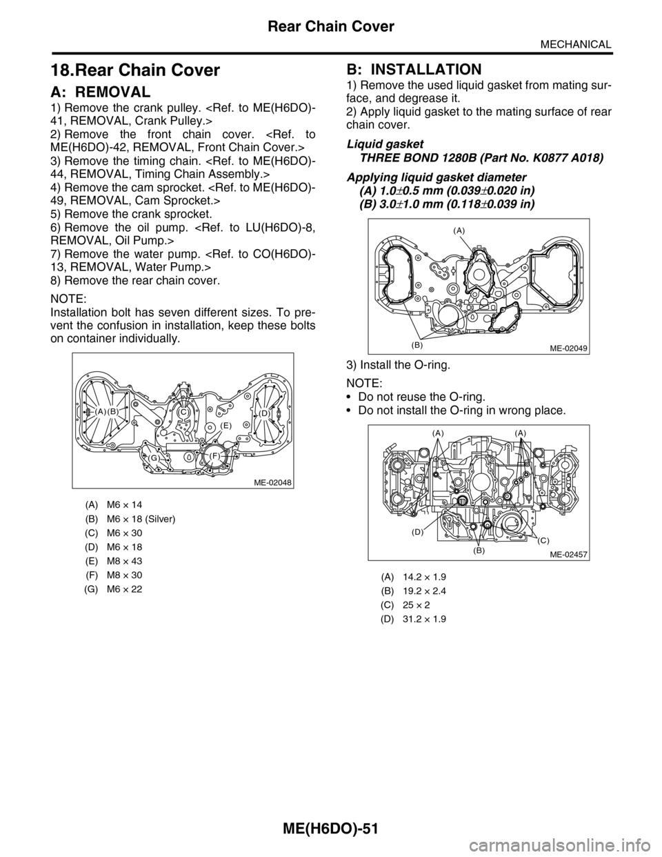
NOTE:
Installation bolt has seven different sizes. To pre-
vent the confusion in installation, keep these bolts
on container individually.
B: INSTALLATION
1) Remove the used liquid gasket from mating sur-
face, and degrease it.
2) Apply liquid gasket to the mating surface of rear
chain cover.
Liquid gasket
THREE BOND 1280B (Part No. K0877 A018)
Applying liquid gasket diameter
(A) 1.0±0.5 mm (0.039±0.020 in)
(B) 3.0±1.0 mm (0.118±0.039 in)
3) Install the O-ring.
NOTE:
•Do not reuse the O-ring.
•Do not install the O-ring in wrong place.
(A) M6 × 14
(B) M6 × 18 (Silver)
(C) M6 × 30
(D) M6 × 18
(E) M8 × 43
(F) M8 × 30
(G) M6 × 22
ME-02048
(F)
(C)(D)
(E)
(G)
(A)(B)
(A) 14.2 × 1.9
(B) 19.2 × 2.4
(C) 25 × 2
(D) 31.2 × 1.9
(A)
(B)ME-02049
(B)
(D)(C)
(A)(A)
ME-02457
Page 1918 of 2453
ME(H6DO)-52
Rear Chain Cover
MECHANICAL
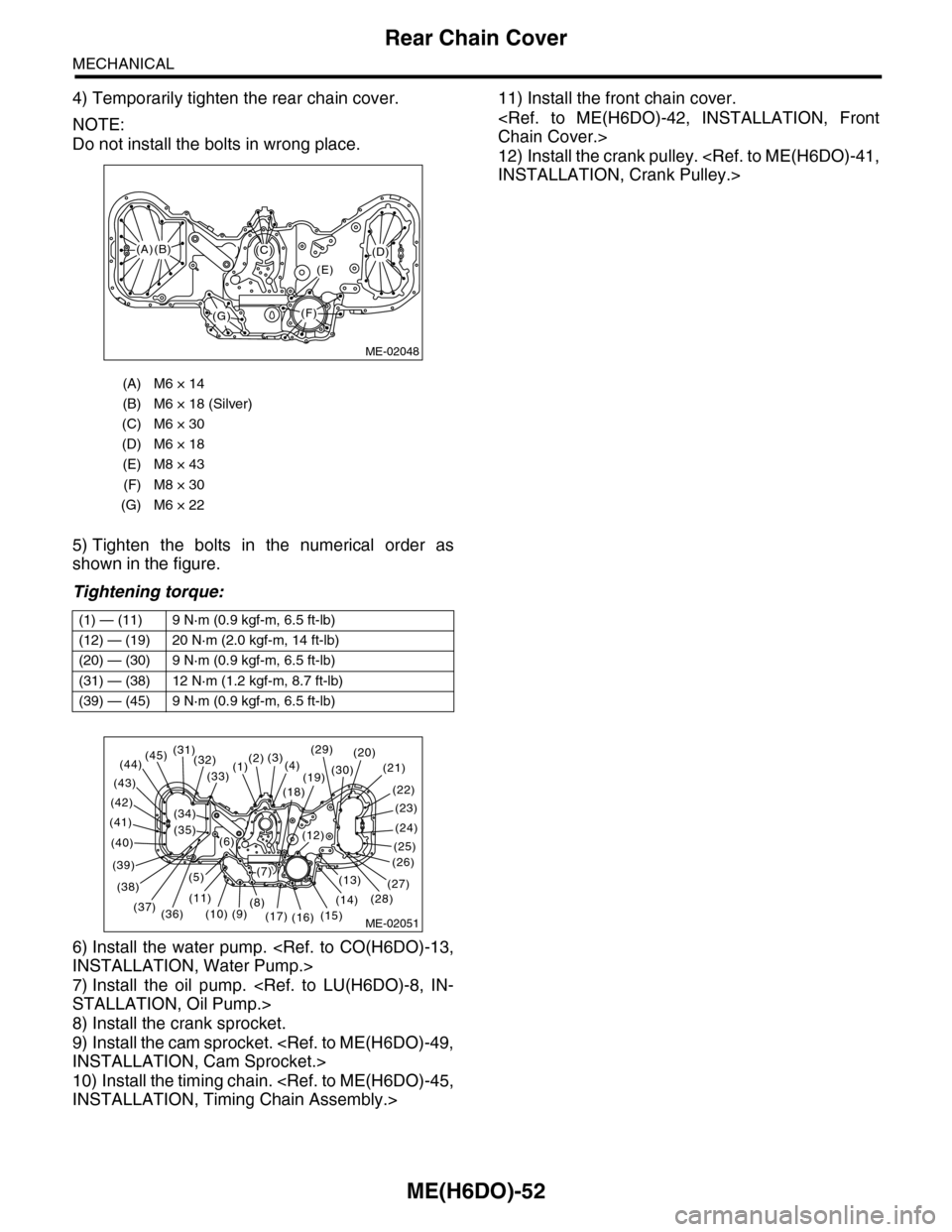
4) Temporarily tighten the rear chain cover.
NOTE:
Do not install the bolts in wrong place.
5) Tighten the bolts in the numerical order as
shown in the figure.
Tightening torque:
6) Install the water pump.
INSTALLATION, Water Pump.>
7) Install the oil pump.
STALLATION, Oil Pump.>
8) Install the crank sprocket.
9) Install the cam sprocket.
INSTALLATION, Cam Sprocket.>
10) Install the timing chain.
INSTALLATION, Timing Chain Assembly.>
11) Install the front chain cover.
Chain Cover.>
12) Install the crank pulley.
INSTALLATION, Crank Pulley.>
(A) M6 × 14
(B) M6 × 18 (Silver)
(C) M6 × 30
(D) M6 × 18
(E) M8 × 43
(F) M8 × 30
(G) M6 × 22
(1) — (11) 9 N·m (0.9 kgf-m, 6.5 ft-lb)
(12) — (19) 20 N·m (2.0 kgf-m, 14 ft-lb)
(20) — (30) 9 N·m (0.9 kgf-m, 6.5 ft-lb)
(31) — (38) 12 N·m (1.2 kgf-m, 8.7 ft-lb)
(39) — (45) 9 N·m (0.9 kgf-m, 6.5 ft-lb)
ME-02048
(F)
(C)(D)
(E)
(G)
(A)(B)
ME-02051(15)
(14)
(26)
(27)(13)
(25)
(24)
(23)
(22)
(21)(20)
(16)(17)
(12)
(19)(30)
(18)
(4)(3)(2)(1)(33)
(8)(9)(10)
(11)
(32)(31)(45)(44)
(43)
(42)
(41)
(40)
(39)
(38)
(37)(36)
(5)
(6)
(7)
(29)
(28)
(35)
(34)
Page 1919 of 2453
ME(H6DO)-53
Camshaft
MECHANICAL
19.Camshaft
A: REMOVAL
1) Remove the crank pulley.
41, REMOVAL, Crank Pulley.>
2) Remove the front chain cover.
ME(H6DO)-42, REMOVAL, Front Chain Cover.>
3) Remove the timing chain assembly.
Assembly.>
4) Remove the cam sprocket.
et.>
5) Remove the crank sprocket.
et.>
6) Remove the rear chain cover.
Cover.>
7) Disconnect the oil pipe.
8) Remove the rocker cover (LH).
9) Remove the plugs (LH).
10) Loosen the camshaft cap bolts equally, a little
at a time in alphabetical sequence shown in the fig-
ure.
11) Remove the camshaft caps and camshaft (LH).
NOTE:
Arrange camshaft caps in order so that they can be
installed in their original positions.
12) Similarly, remove the camshafts (RH) and re-
lated parts.(A) Bolt without filter (with white mark)
(B) Bolt with filter (without white mark)
ME-02513
(A)
(B)
ME-02055
ME-02054(1)
(2)
(8)
(7)(9)
(3)
(4)
(5)
(6)(10)
(11)(13)
(14)(12)
(15)
(16)