2009 SUBARU TRIBECA drain bolt
[x] Cancel search: drain boltPage 361 of 2453
AC-35
Heater and Cooling Unit
HVAC SYSTEM (HEATER, VENTILATOR AND A/C)
16.Heater and Cooling Unit
A: REMOVAL
1. FRONT
1) Disconnect the ground cable from battery.
2) Using the refrigerant recovery system, dis-
charge refrigerant.
3) Drain engine coolant from the radiator.
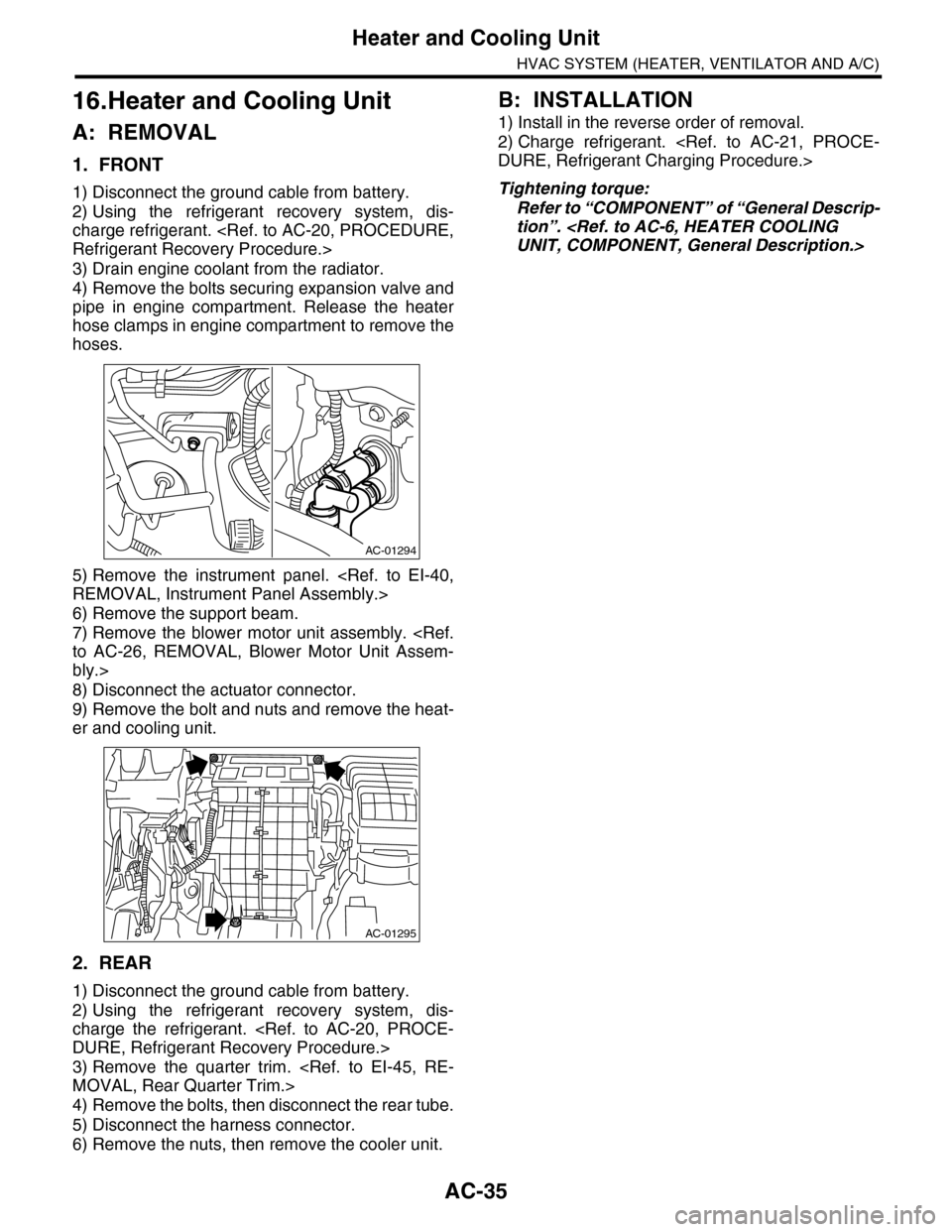
4) Remove the bolts securing expansion valve and
pipe in engine compartment. Release the heater
hose clamps in engine compartment to remove the
hoses.
5) Remove the instrument panel.
6) Remove the support beam.
7) Remove the blower motor unit assembly.
bly.>
8) Disconnect the actuator connector.
9) Remove the bolt and nuts and remove the heat-
er and cooling unit.
2. REAR
1) Disconnect the ground cable from battery.
2) Using the refrigerant recovery system, dis-
charge the refrigerant.
3) Remove the quarter trim.
4) Remove the bolts, then disconnect the rear tube.
5) Disconnect the harness connector.
6) Remove the nuts, then remove the cooler unit.
B: INSTALLATION
1) Install in the reverse order of removal.
2) Charge refrigerant.
Tightening torque:
Refer to “COMPONENT” of “General Descrip-
tion”.
AC-01294
AC-01295
Page 691 of 2453
SR-7
Sunroof Assembly
SUNROOF/T-TOP/CONVERTIBLE TOP (SUNROOF)
4. Sunroof Assembly
A: REMOVAL
1) Disconnect the ground cable from battery.
2) Remove the roof trim.
3) Disconnect the harness connector of sunroof
motor.
4) Remove the glass lid.
5) Remove the drain tube from frame assembly.
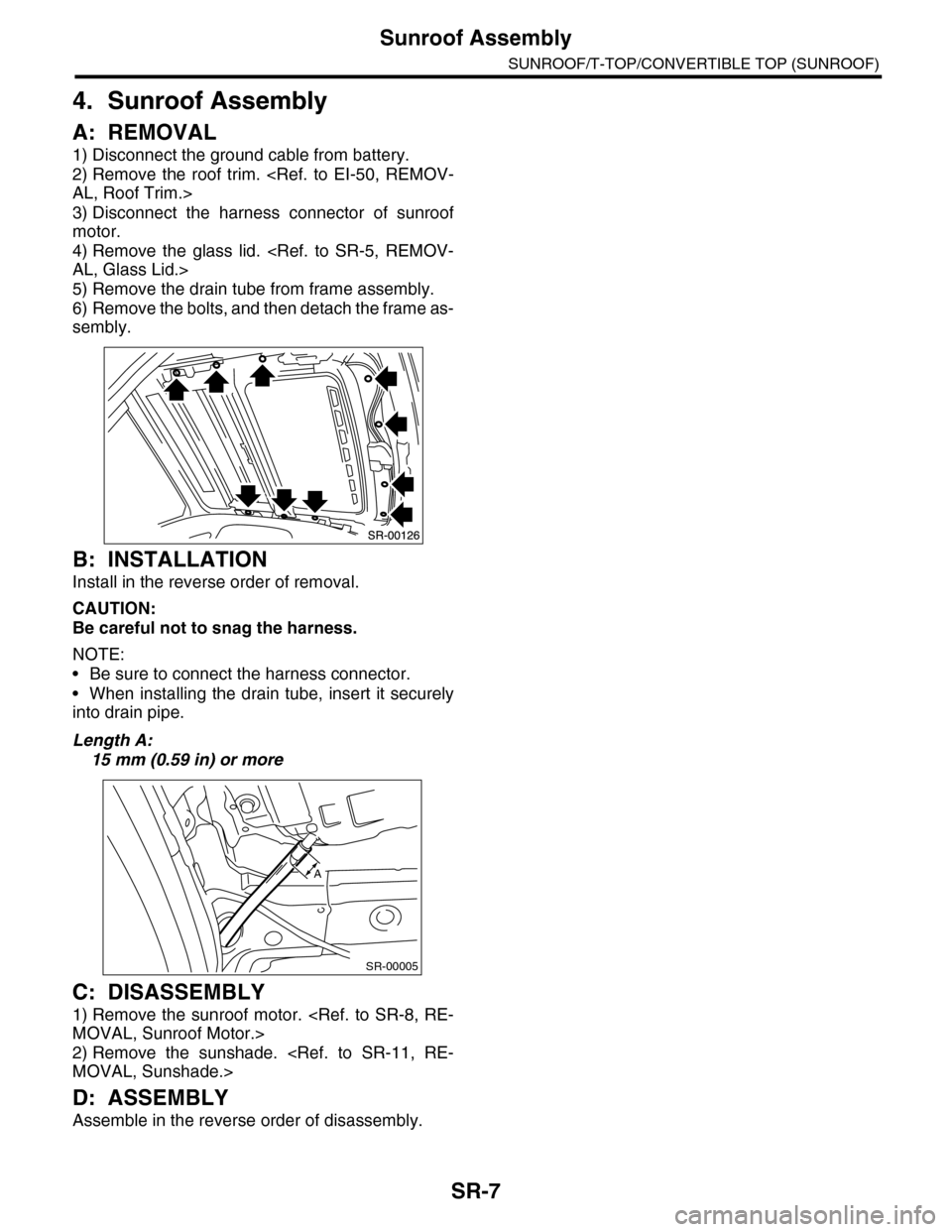
6) Remove the bolts, and then detach the frame as-
sembly.
B: INSTALLATION
Install in the reverse order of removal.
CAUTION:
Be careful not to snag the harness.
NOTE:
•Be sure to connect the harness connector.
•When installing the drain tube, insert it securely
into drain pipe.
Length A:
15 mm (0.59 in) or more
C: DISASSEMBLY
1) Remove the sunroof motor.
2) Remove the sunshade.
D: ASSEMBLY
Assemble in the reverse order of disassembly.
SR-00005
A
Page 788 of 2453

DI-4
General Description
DIFFERENTIALS
B: COMPONENT
1. REAR DIFFERENTIAL (VA2-TYPE)
(1) Hypoid driven gear and drive pin-
ion set
(13) Lock plate (26) Clip
(14) Side bearing (27) Stay ground
(2) Pinion height adjusting washer (15) O–ring (28)
Rear differential oil temperature
switch(3) Rear bearing (16) Axle shaft holder
(4) Bearing preload adjusting collar (17) Side oil seal
(5) Bearing preload adjusting washer (18) Differential case ASSYTightening torque: N·m (kgf-m, ft-lb)
(6) Differential carrier (19) Air breather hoseT1: 25 (2.5, 18.1)
(7) Front bearing (20) Stud boltT2: 29 (3.0, 21.4)
(8) Collar (21) GasketT3: 34 (3.5, 25.3)
(9) Pilot bearing (22) Oil filler plugT4: 60 (6.1, 44.3)
(10) Front oil seal (23) Oil drain plugT5: 62 (6.3, 45.6)
(11) Companion flange (24) Rear coverT6: 191 (19.5, 141)
(12) Self–locking nut (25) Gasket
Page 801 of 2453

DI-17
Rear Differential (VA–type)
DIFFERENTIALS
12) Tighten the self-locking nut.
Tightening torque:
70 N·m (7.1 kgf-m, 51 ft-lb)
13) Lower the transmission jack.
14) Install the air breather hose to the sub frame.
15) Install the propeller shaft.
16) Install the heat shield cover.
17) Install the rear exhaust pipe and muffler.
C: DISASSEMBLY
To detect the real cause of trouble, inspect the fol-
lowing items before disassembling.
•Tooth contact and backlash between hypoid driv-
en gear and drive pinion
•Total preload of drive pinion
1) Remove the air breather hose.
2) Set the ST on vise and install the differential as-
sembly to ST.
ST 398217700 ATTACHMENT SET
3) Drain the gear oil by removing the plug.
4) Remove the rear differential oil temperature
switch.
5) Remove the rear cover by loosening retaining
bolts.
6) Remove the lock plate RH and LH.
7) Remove the holder RH and LH with ST.
ST 18630AA010 WRENCH ASSY
8) Pull out the differential case assembly from dif-
ferential carrier.
NOTE:
Be careful so that the teeth do not to hit against the
case.
DI-00269
STDI-00363
DI-00388
DI-00364
ST
DI-00365
DI-00366
Page 818 of 2453

DI-34
General Diagnostic Table
DIFFERENTIALS
8. General Diagnostic Table
A: INSPECTION
Symptom or trouble Possible cause Remedy
1. Oil leakage(1) Worn, scratched, or incorrectly seated
front or side oil seal. Scored, battered or
excessively wor n sliding surface of com-
panion flange.
Correct or replace.
(2) Clogged or damaged air breather. Clean, repair or replace.
(3) Loose bolts on differential spindle or
side retainer, or incorrectly fitted O-ring.
Tighten the bolts to specified torque.
Replace the O-ring.
(4) Loose rear cover attaching bolts or
damaged gasket.
Tighten the bolts to specified torque.
Replace gasket and apply liquid gasket.
(5) Loose oil filler or drain plug. Retighten and apply liquid gasket.
(6) Wear, damage or incorrect fitting of
spindle, side retainer or oil seal.
Correct or replace.
2. Seizure
NOTE:Seized or damaged parts should be re-
placed, and also other parts should be thor-
oughly checked for any defect and should
be repaired or replaced as required.
(1) Insufficient backlash for hypoid gear. Readjust or replace.
(2) Excessive preload for side, rear or
front bearing.
Readjust or replace.
(3) Insufficient or improper oil used. Replace seized part and fill with speci-
fied oil to specified level.
3. Damage
NOTE:Damaged parts should be replaced, and
also other parts should be thoroughly
checked for any defect and should be re-
paired or replaced as required.
(1) Improper backlash for hypoid gear. Replace.
(2) Insufficient or excessive preload for
side, rear or front bearing.
Readjust or replace.
(3) Excessive backlash for differential
gear.
Replace gear or thrust washer.
(4) Loose bolts and nuts such as hypoid
driven gear bolt
Retighten.
(5) Damage due to overloading. Replace.
4. Noises when starting or shifting
gears
NOTE:
Noises may be caused by differential as-
sembly, universal joint, wheel bearing, etc.
Find out what is actually making noise be-
fore disassembling.
(1) Excessive backlash for hypoid gear. Readjust.
(2) Excessive backlash for differential
gear.
Replace the differential case assembly.
(3) Insufficient preload for front or rear
bearing.
Readjust.
(4) Loose drive pinion nut. Tighten to the specified torque.
(5) Loose bolts and nuts such as side
bearing retainer attaching bolt.
Tighten to the specified torque.
5. Noises when cornering(1) Damaged differential gear. Replace the differential case assembly.
(2) Excessive wear or damage of thrust
washer.
Replace the differential case assembly.
(3) Broken pinion mate shaft. Replace the differential case assembly.
(4) Seized or damaged side bearing. Replace.
6. Gear Noise
NOTE:
Since noises from engine, muffler, trans-
mission, propeller shaft, wheel bearings,
tires, and body are sometimes mistaken for
noises from differential assembly, be care-
ful in checking them. Inspection methods to
locate noises include coasting, accelerat-
ing, cruising, and jacking-up all four wheels.
Perform these inspections according to the
condition of trouble. When listening to nois-
es, shift gears into four wheel drive and
fourth speed position, trying to pick up only
differential noise.
(1) Improper tooth contact of hypoid gear. Readjust or replace hypoid gear set.
(2) Improper backlash of the hypoid gear. Readjust.
(3) Scored or chipped teeth of hypoid
gear.
Replace hypoid gear set.
(4) Seized hypoid gear. Replace hypoid gear set.
(5) Improper preload for front or rear
bearings.
Readjust.
(6) Seized, cut-away or chipped front or
rear bearing.
Replace.
(7) Seized, cut-away or chipped side
bearing.
Replace.
(8) Differential carrier is vibrating. Replace the differential case assembly.
Page 927 of 2453
PS-47
Reservoir Tank
POWER ASSISTED SYSTEM (POWER STEERING)
8. Reservoir Tank
A: REMOVAL
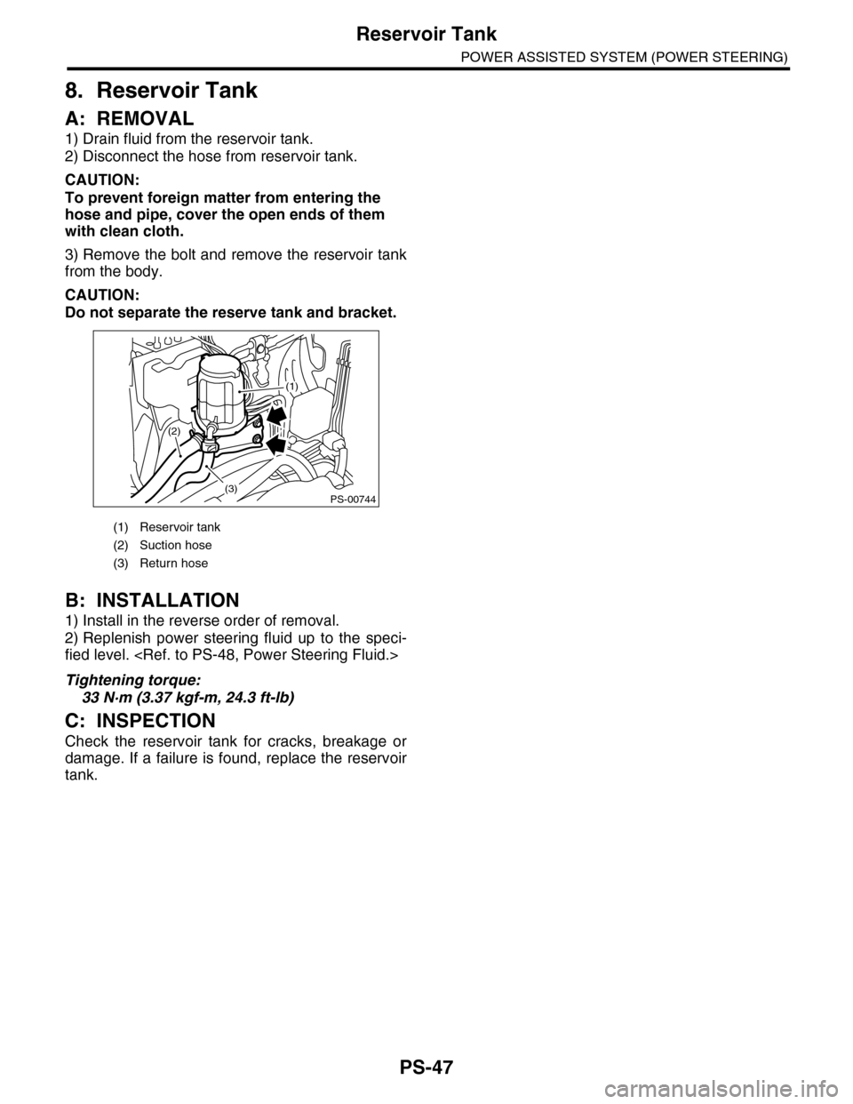
1) Drain fluid from the reservoir tank.
2) Disconnect the hose from reservoir tank.
CAUTION:
To prevent foreign matter from entering the
hose and pipe, cover the open ends of them
with clean cloth.
3) Remove the bolt and remove the reservoir tank
from the body.
CAUTION:
Do not separate the reserve tank and bracket.
B: INSTALLATION
1) Install in the reverse order of removal.
2) Replenish power steering fluid up to the speci-
fied level.
Tightening torque:
33 N·m (3.37 kgf-m, 24.3 ft-lb)
C: INSPECTION
Check the reservoir tank for cracks, breakage or
damage. If a failure is found, replace the reservoir
tank.
(1) Reservoir tank
(2) Suction hose
(3) Return hose
PS-00744(3)
(2)
(1)
Page 1134 of 2453
CO(H6DO)-15
Radiator
COOLING
6. Radiator
A: REMOVAL
WARNING:
The radiator is pressurized. Wait until engine
cools down before working on the radiator.
1) Set the vehicle on a lift.
2) Remove the collector cover.
3) Disconnect the ground cable from battery.
4) Lift-up the vehicle.
5) Remove the under cover.
6) Drain engine coolant completely.
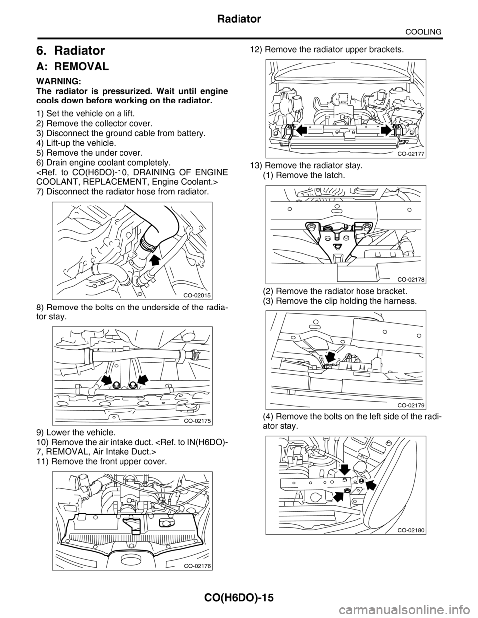
7) Disconnect the radiator hose from radiator.
8) Remove the bolts on the underside of the radia-
tor stay.
9) Lower the vehicle.
10) Remove the air intake duct.
11) Remove the front upper cover.
12) Remove the radiator upper brackets.
13) Remove the radiator stay.
(1) Remove the latch.
(2) Remove the radiator hose bracket.
(3) Remove the clip holding the harness.
(4) Remove the bolts on the left side of the radi-
ator stay.
CO-02015
CO-02175
CO-02176
CO-02177
CO-02179
CO-02180
Page 1598 of 2453
FU(H6DO)-37
Fuel
FUEL INJECTION (FUEL SYSTEMS)
21.Fuel
A: PROCEDURE
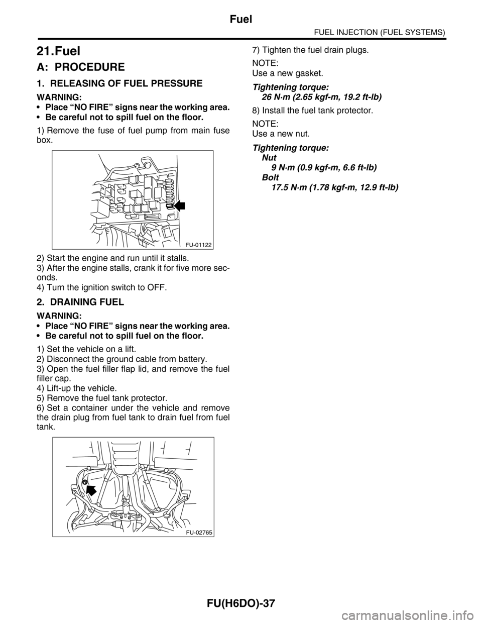
1. RELEASING OF FUEL PRESSURE
WARNING:
•Place “NO FIRE” signs near the working area.
•Be careful not to spill fuel on the floor.
1) Remove the fuse of fuel pump from main fuse
box.
2) Start the engine and run until it stalls.
3) After the engine stalls, crank it for five more sec-
onds.
4) Turn the ignition switch to OFF.
2. DRAINING FUEL
WARNING:
•Place “NO FIRE” signs near the working area.
•Be careful not to spill fuel on the floor.
1) Set the vehicle on a lift.
2) Disconnect the ground cable from battery.
3) Open the fuel filler flap lid, and remove the fuel
filler cap.
4) Lift-up the vehicle.
5) Remove the fuel tank protector.
6) Set a container under the vehicle and remove
the drain plug from fuel tank to drain fuel from fuel
tank.
7) Tighten the fuel drain plugs.
NOTE:
Use a new gasket.
Tightening torque:
26 N·m (2.65 kgf-m, 19.2 ft-lb)
8) Install the fuel tank protector.
NOTE:
Use a new nut.
Tightening torque:
Nut
9 N·m (0.9 kgf-m, 6.6 ft-lb)
Bolt
17.5 N·m (1.78 kgf-m, 12.9 ft-lb)
FU-01122
FU-02765