Page 857 of 2453
FS-9
Wheel Alignment
FRONT SUSPENSION
4) Tighten two new self–locking nuts.
Tightening torque:
175 N·m (17.9 kgf-m, 129 ft-lb)
3. CASTER
•INSPECTION
1) Place the front wheel on the turning radius
gauge. Make sure the ground contact surfaces of
front and rear wheels are at the same height.
2) Set the adapter at the center of wheel, and then
attach the wheel alignment gauge.
3) Measure the caster angle in accordance with the
operation manual for wheel alignment gauge.
To i n c r e a s e c a m b e r :
Rotate the left side counterclockwise. Rotate the right side clockwise.
To d e c r e a s e c a m b e r :
Rotate the left side clockwise. Rotate the right side counterclockwise.
FS-00197FS-00198
FS-00198FS-00197
(1) Alignment gauge
(2) Turning radius gauge
(3) Adapter
FS-00213
(1)
(2)
(3)
Caster
4°04′(Reference)
Page 858 of 2453

FS-10
Wheel Alignment
FRONT SUSPENSION
4. STEERING ANGLE
•INSPECTION
•ADJUSTMENT
1) Turn the tie-rod to adjust the steering angle of
both inner and outer wheels.
2) Check the toe–in.
NOTE:
Correct the boot if it is twisted.
5. FRONT WHEEL TOE–IN
•INSPECTION
Toe-in:
0±3 mm (0±0.12 in)
1) Set the toe-in gauge in the position at wheel axis
center height behind the right and left front tires.
2) Place a mark at the center of both left and right
tires, and measure distance “A” between the
marks.
3) Move the vehicle forward to rotate the tires 180°.
NOTE:
Be sure to rotate the tires in the forward direction.
4) Measure distance “B” between the left and right
marks. Find toe–in using the following equation:
A – B = Toe–in
•ADJUSTMENT
When adjusting the toe-in, adjust it to the following
value.
Toe-in:
0±2 mm (0±0.08 in)
1) Check that the left and right wheel steering an-
gles are within specification.
2) Loosen the left and right side steering tie–rod
lock nuts.
3) Turn the left and right tie–rods by equal amounts
until the toe–in is at the specification.
Both the left and right tie–rods are right–hand
threaded. To increase toe–in, turn both tie–rods
clockwise by equal amount (viewing from the inside
of vehicle).
4) Tighten the tie–rod lock nut.
Tightening torque:
85 N·m (8.7 kgf-m, 62.7 ft-lb)
NOTE:
Check and correct the tie rod boot if twisted.
6. REAR WHEEL TOE–IN
•INSPECTION
Toe-in:
2±2 mm (0.08±0.08 in)
Refer to FRONT WHEEL TOE–IN for rear toe–in
inspection procedures.
SPECTION, Wheel Alignment.>
Inner wheel Outer wheel
37.0°±1.5° 32.0°±1.5°
(1) Lock nut
FS-00014
(1)
FS-00015
AB
(1) Lock nut
FS-00014
(1)
Page 897 of 2453

PS-17
Steering Gearbox
POWER ASSISTED SYSTEM (POWER STEERING)
5. Steering Gearbox
A: REMOVAL
1) Set the vehicle on a lift.
2) Disconnect the ground cable from the battery.
3) Lift-up the vehicle, and remove the front wheels.
4) Remove the under cover.
MOVAL, Front Under Cover.>
5) Remove the front exhaust pipe assembly. (Non–
turbo model)
Front Exhaust Pipe.>
WARNING:
Be careful not to burn yourself because the ex-
haust pipe is hot.
6) After pulling off the cotter pin and removing the
castle nut, use a puller to remove the tie–rod end
from the knuckle arm.
7) Remove the front crossmember support plate,
jack-up plate and front stabilizer.
REMOVAL, Front Stabilizer.>
8) Remove the one pipe joint at the center of the
gearbox, and connect the vinyl hose to the pipe and
the joint. Discharge the fluid by turning the steering
wheel fully clockwise and counterclockwise. Dis-
charge the fluid similarly from other pipes.
9) Remove the universal joint.
MOVAL, Universal Joint.>
10) Disconnect the pipe C from pressure hose first,
then disconnect pipe D from the return hose.
(1) Castle nut
(2) Tie–rod end
(3) Knuckle arm
(1) Crossmember support plate
(2) Jack–up plate
PS-00043
(2)(1)
(1)
FS-00200
(1) Pipe A
(2) Pipe B
(1) Pipe C
(2) Pipe D
(3) Pressure hose
(4) Return hose
(2)
PS-00553
(1)
PS-00538
(4)
(3)
(2)
(1)
Page 1893 of 2453

ME(H6DO)-27
Valve Clearance
MECHANICAL
8. Valve Clearance
A: INSPECTION
Inspection and adjustment of valve clearance
should be performed while engine is cold.
1) Set the vehicle on a lift.
2) Remove the collector cover.
3) Disconnect the ground cable from battery.
4) Lift-up the vehicle.
5) Remove the under cover.
6) Lower the vehicle.
7) When inspecting RH side cylinders:
(1) Remove the air intake duct and air cleaner
case.
take Duct.>
Air Cleaner Case.>
(2) Remove the fuel tank protector (RH).
(3) Disconnect the connector of oil pressure
switch.
(4) Remove the ignition coil.
IG(H6DO)-7, REMOVAL, Ignition Coil & Ignitor
Assembly.>
(5) Remove the rocker cover (RH).
8) When inspecting LH side cylinders:
(1) Disconnect the battery cable, and then re-
move the battery and battery carrier.
(2) Disconnect the PCV hose and blow-by hose
from rocker cover (LH).
(3) Remove the fuel pipe protector (LH).
(4) Remove the ignition coil.
IG(H6DO)-7, REMOVAL, Ignition Coil & Ignitor
Assembly.>
(5) Remove the rocker cover (LH).
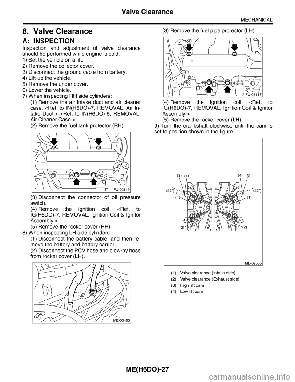
9) Turn the crankshaft clockwise until the cam is
set to position shown in the figure.
FU-02119
ME-00460
(1) Valve clearance (Intake side)
(2) Valve clearance (Exhaust side)
(3) High lift cam
(4) Low lift cam
FU-02117
ME-02565
(4)(3)(3)(4)
(1)
(2)
(1)
(2)
(23 )(23 )
Page 1926 of 2453

ME(H6DO)-60
Cylinder Head
MECHANICAL
(3) Turn the cylinder head upside down and
place the ST as shown in the figure.
ST 18251AA040 VALVE GUIDE ADJUSTER
(4) Before installing a new valve guide, make
sure that neither scratches nor damages exist
on the inner surface of valve guide holes in cyl-
inder head.
(5) Put a new valve guide, coated with sufficient
oil, in cylinder, and insert the ST1 into valve
guide. Press in until the valve guide upper end
is flush with the upper surface of ST2.
ST1 499765700 VALVE GUIDE REMOVER
ST2 18251AA040 VALVE GUIDE ADJUSTER
(6) Check the valve guide protrusion.
Valve guide protrusion L:
11.4 — 11.8 mm (0.449 — 0.465 in)
(7) Ream the inside of valve guide using ST.
Put the reamer in valve guide, and rotate the
reamer slowly clockwise while pushing it lightly.
Bring the reamer back while rotating it clock-
wise. After reaming, clean the valve guide to re-
move chips.
ST 499765900 VALVE GUIDE REAMER
NOTE:
•Apply engine oil to the reamer when reaming.
•If the inner surface of valve guide is damaged,
the edge of reamer should be slightly ground with
oil stone.
•If the inner surface of valve guide becomes lus-
trous and the reamer does not chip, use a new
reamer or remedy the reamer.
(8) Recheck the contact condition between
valve and valve seat after replacing the valve
guide.
4. INTAKE AND EXHAUST VALVE
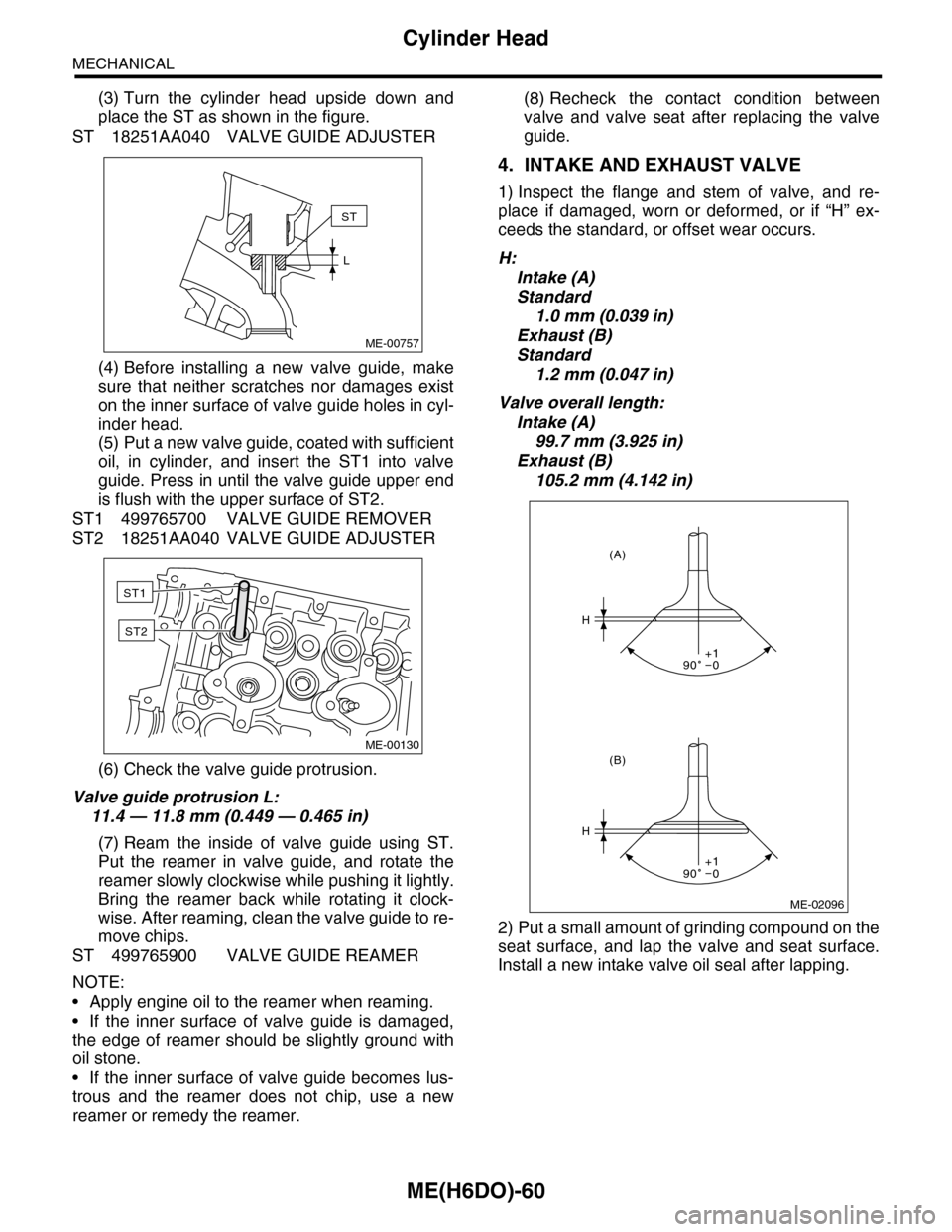
1) Inspect the flange and stem of valve, and re-
place if damaged, worn or deformed, or if “H” ex-
ceeds the standard, or offset wear occurs.
H:
Intake (A)
Standard
1.0 mm (0.039 in)
Exhaust (B)
Standard
1.2 mm (0.047 in)
Valve overall length:
Intake (A)
99.7 mm (3.925 in)
Exhaust (B)
105.2 mm (4.142 in)
2) Put a small amount of grinding compound on the
seat surface, and lap the valve and seat surface.
Install a new intake valve oil seal after lapping.
ME-00757
ST
L
ME-00130
ST1
ST2
ME-02096
H
H
(B)
(A)
90 0+1
90 0+1