2009 SUBARU TRIBECA service indicator
[x] Cancel search: service indicatorPage 586 of 2453

OD(diag)-18
Subaru Select Monitor
OCCUPANT DETECTION SYSTEM (DIAGNOSTICS)
3. CLEAR MEMORY MODE
Clear the DTC stored in the airbag control module
after repairing the airbag system and occupant de-
tection system. (After the breakdown is recovered,
the breakdown code for completed recoveries are
read out when the next breakdown occurs if the
memory clear work is not performed.)
1) On the «Main Menu» display screen, select the
{Each System Check} and press the [YES] key.
2) On the «System Selection Menu» display
screen, select the {Airbag System} and press the
[YES] key.
3) On the {Airbag System} menu screen, select the
{Clear Memory} and press the [YES] key.
4) When the “Clear Memory?” is shown on the
screen, press the [YES] key.
5) When “Done” is displayed, turn the Subaru Se-
lect Monitor to OFF.
NOTE:
For details concerning operation procedure, refer
to the “SUBARU SELECT MONITOR OPERATION
MANUAL”.
4. SYSTEM CALIBRATION (REZEROING)
NOTE:
When replacing the occupant detection system, or
removing and disassembling the passenger’s seat,
always perform the system calibration after install-
ing a seat in the vehicle.
CAUTION:
When the trouble occurs in the system during
calibration process, “Occupant detection cali-
bration failure” is detected in the DTC 2A of the
airbag system and the airbag warning light
lights. In this case, after turning the ignition
switch to OFF once, redo the system calibration
(Rezeroing), or after clearing the cause of the
failure, perform the system calibration again.
1) Park empty vehicle on a level surface.
2) On the «Main Menu» display screen, select the
{Each System Check} and press the [YES] key.
3) On the «System Selection Menu» display
screen, select the {Occupant Detection System}
and press the [YES] key.
4) On the Occupant Detection System display
screen, select the {Zero Point Adjustment} and
press the [YES] key.
5) “See service manual. And check vehicle condi-
tion for successfully completing the rezeroing.” is
displayed. Check the following to adjust the condi-
tion of the vehicle.
•Adjust the seat backrest to be vertical. (Press the
power seat switch to put the seat in a position
where it will not move.)
•Adjust the seat sliding position to all the way
back. (Press the power seat switch to put the seat
in a position where it will not move.)
•Do not place anything on the top of the seat
cushion.
•Sit on the seat cushion to smooth the seat sur-
face.
•Check that the passenger’s seat belt is not in-
serted into the buckle, not tense or not stuck.
•Check that ambient temperature is in a range
from 0 to 40°C.
6) When the «Re-zeroing Adjust the passenger
seat to the condition shown in service manual» is
displayed, slide the passenger seat all the way to
the back, check that the backrest is adjusted to all
the way up, and press the [YES] key.
7) When the «Re-zeroing Unbelt the Passenger
seatbelt Continue: YES, Quit: NO» is displayed,
make sure the passenger’s seatbelt is disconnect-
ed from the buckle and press the [YES] key.
8) When the «Re-zeroing Empty the passenger
seat Continue: YES, Quit: NO» is displayed, make
sure that the passenger’s seat is empty, air bag
OFF indicator illuminates and air bag ON indicator
does not illuminate, and press the [YES] key.
NOTE:
•After pressing the [YES] key, «Now processing
.... Wait for a while. Do not touch or give impact to
vehicle and seat» is displayed. Do not touch or rock
the vehicle while the message is displayed.
•During the system calibration process, if the
«Re-zeroing is unsuccessful See service manual
Press YES to END» is displayed, go to step 10).
9) When the re-zeroing is ended normally, the«Re-
zeroing is successfully completed Press YES to
END» is displayed. Press the [YES] key and turn
the ignition switch to OFF to finish the diagnosis.
OD-00025
Page 829 of 2453

DS-12
Propeller Shaft
DRIVE SHAFT SYSTEM
3. RUNOUT OF PROPELLER SHAFT
1) Remove the center exhaust pipe.
2) Remove the rear exhaust pipe and muffler.
3) Remove the heat shield cover.
4) Set the dial gauge with its indicator stem at the
center of the propeller shaft tube.
5) Turn the propeller shaft slowly by hands to check
for runout of the propeller shaft.
Runout:
Service limit 0.6 mm (0.024 in)
4. CENTER BEARING FREE PLAY
1) Remove the front and center exhaust pipes.
2) Remove the rear exhaust pipe and muffler.
3) Remove the heat shield cover.
4) Move the propeller shaft near the center bearing
up, down, left, right by hand, to check for any ab-
normal free play of the bearings.
(A) Propeller shaft
(B) Dial gauge
DS-00036
(B)
(A)
DS-00037
Page 1441 of 2453
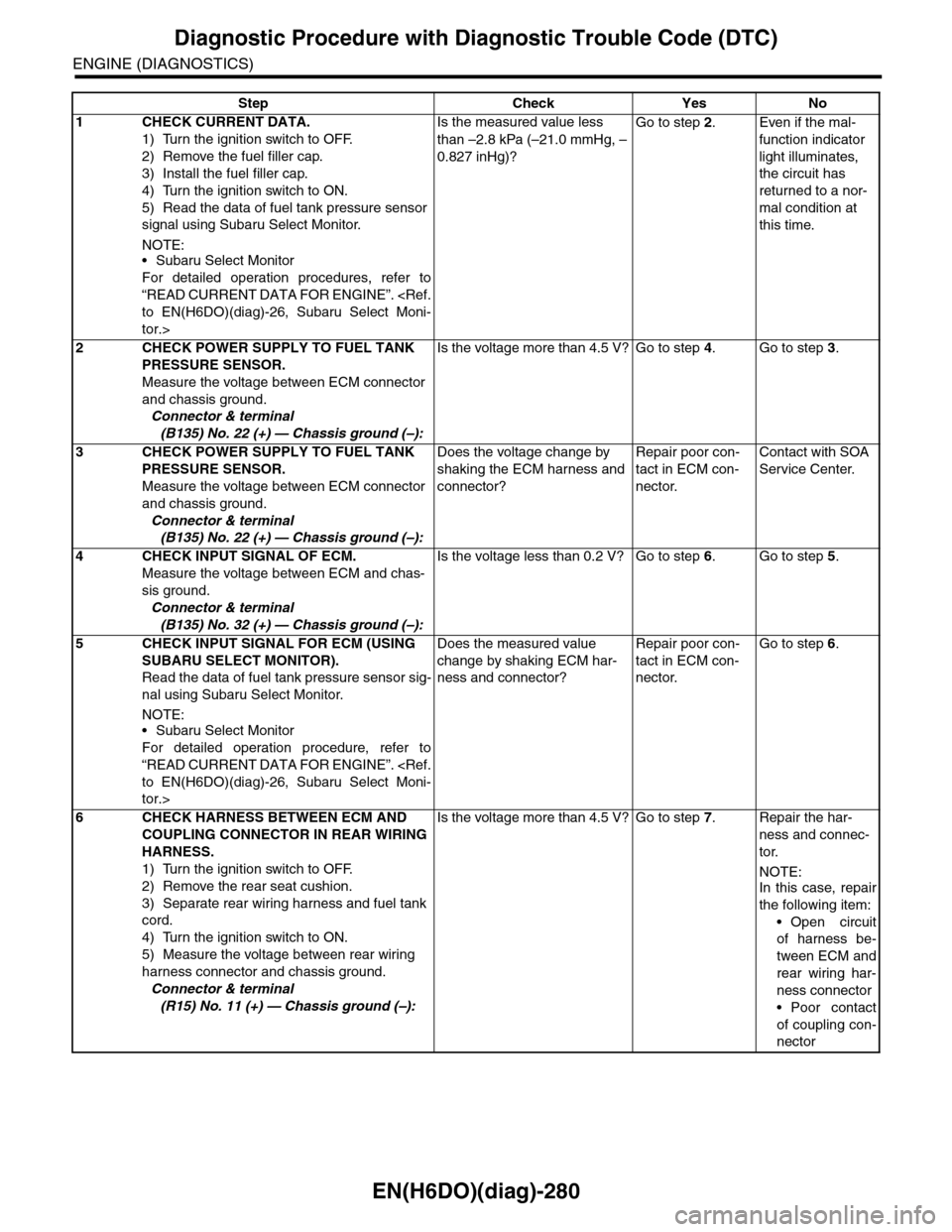
EN(H6DO)(diag)-280
Diagnostic Procedure with Diagnostic Trouble Code (DTC)
ENGINE (DIAGNOSTICS)
Step Check Yes No
1CHECK CURRENT DATA.
1) Turn the ignition switch to OFF.
2) Remove the fuel filler cap.
3) Install the fuel filler cap.
4) Turn the ignition switch to ON.
5) Read the data of fuel tank pressure sensor
signal using Subaru Select Monitor.
NOTE:•Subaru Select Monitor
For detailed operation procedures, refer to
“READ CURRENT DATA FOR ENGINE”.
tor.>
Is the measured value less
than –2.8 kPa (–21.0 mmHg, –
0.827 inHg)?
Go to step 2.Even if the mal-
function indicator
light illuminates,
the circuit has
returned to a nor-
mal condition at
this time.
2CHECK POWER SUPPLY TO FUEL TANK
PRESSURE SENSOR.
Measure the voltage between ECM connector
and chassis ground.
Connector & terminal
(B135) No. 22 (+) — Chassis ground (–):
Is the voltage more than 4.5 V? Go to step 4.Go to step 3.
3CHECK POWER SUPPLY TO FUEL TANK
PRESSURE SENSOR.
Measure the voltage between ECM connector
and chassis ground.
Connector & terminal
(B135) No. 22 (+) — Chassis ground (–):
Does the voltage change by
shaking the ECM harness and
connector?
Repair poor con-
tact in ECM con-
nector.
Contact with SOA
Service Center.
4CHECK INPUT SIGNAL OF ECM.
Measure the voltage between ECM and chas-
sis ground.
Connector & terminal
(B135) No. 32 (+) — Chassis ground (–):
Is the voltage less than 0.2 V? Go to step 6.Go to step 5.
5CHECK INPUT SIGNAL FOR ECM (USING
SUBARU SELECT MONITOR).
Read the data of fuel tank pressure sensor sig-
nal using Subaru Select Monitor.
NOTE:
•Subaru Select Monitor
For detailed operation procedure, refer to
“READ CURRENT DATA FOR ENGINE”.
tor.>
Does the measured value
change by shaking ECM har-
ness and connector?
Repair poor con-
tact in ECM con-
nector.
Go to step 6.
6CHECK HARNESS BETWEEN ECM AND
COUPLING CONNECTOR IN REAR WIRING
HARNESS.
1) Turn the ignition switch to OFF.
2) Remove the rear seat cushion.
3) Separate rear wiring harness and fuel tank
cord.
4) Turn the ignition switch to ON.
5) Measure the voltage between rear wiring
harness connector and chassis ground.
Connector & terminal
(R15) No. 11 (+) — Chassis ground (–):
Is the voltage more than 4.5 V? Go to step 7.Repair the har-
ness and connec-
tor.
NOTE:In this case, repair
the following item:
•Open circuit
of harness be-
tween ECM and
rear wiring har-
ness connector
•Poor contact
of coupling con-
nector
Page 1897 of 2453
ME(H6DO)-31
V-belt
MECHANICAL
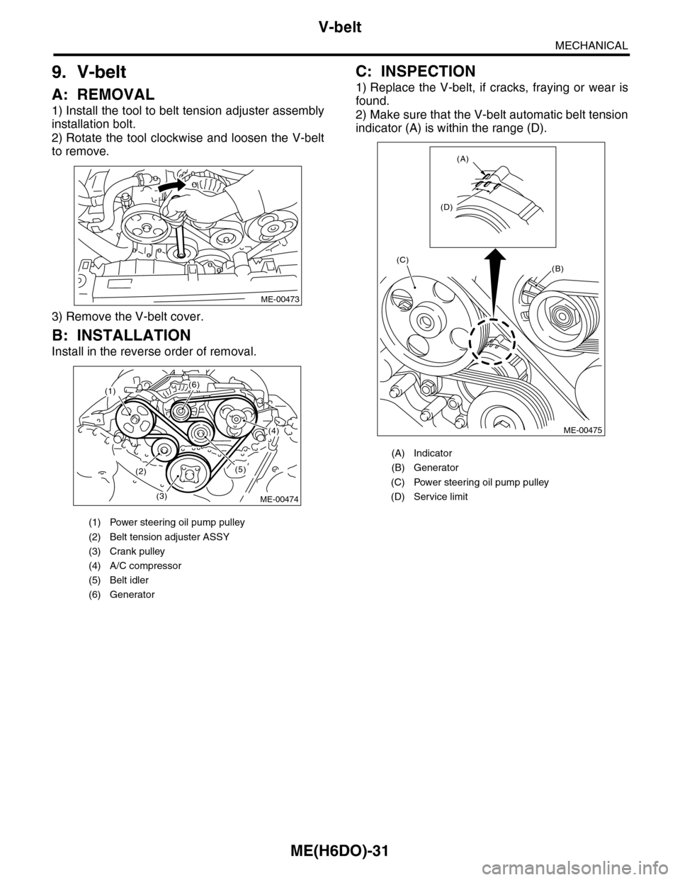
9. V-belt
A: REMOVAL
1) Install the tool to belt tension adjuster assembly
installation bolt.
2) Rotate the tool clockwise and loosen the V-belt
to remove.
3) Remove the V-belt cover.
B: INSTALLATION
Install in the reverse order of removal.
C: INSPECTION
1) Replace the V-belt, if cracks, fraying or wear is
found.
2) Make sure that the V-belt automatic belt tension
indicator (A) is within the range (D).
(1) Power steering oil pump pulley
(2) Belt tension adjuster ASSY
(3) Crank pulley
(4) A/C compressor
(5) Belt idler
(6) Generator
ME-00473
(1)(6)
(4)
(5)(2)
(3)ME-00474
(A) Indicator
(B) Generator
(C) Power steering oil pump pulley
(D) Service limit
(B)
(A)
(D)
(C)
ME-00475
Page 1982 of 2453
SC(H6DO)-24
Generator
STARTING/CHARGING SYSTEMS
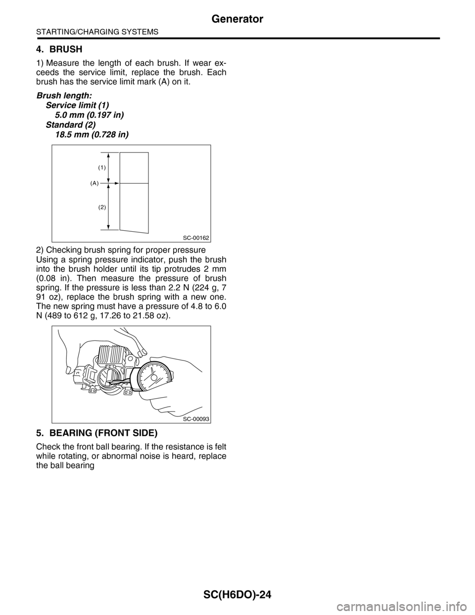
4. BRUSH
1) Measure the length of each brush. If wear ex-
ceeds the service limit, replace the brush. Each
brush has the service limit mark (A) on it.
Brush length:
Service limit (1)
5.0 mm (0.197 in)
Standard (2)
18.5 mm (0.728 in)
2) Checking brush spring for proper pressure
Using a spring pressure indicator, push the brush
into the brush holder until its tip protrudes 2 mm
(0.08 in). Then measure the pressure of brush
spring. If the pressure is less than 2.2 N (224 g, 7
91 oz), replace the brush spring with a new one.
The new spring must have a pressure of 4.8 to 6.0
N (489 to 612 g, 17.26 to 21.58 oz).
5. BEARING (FRONT SIDE)
Check the front ball bearing. If the resistance is felt
while rotating, or abnormal noise is heard, replace
the ball bearing
SC-00162
(A)
(1)
(2)
SC-00093
Page 1986 of 2453
PM-3
Schedule
PERIODIC MAINTENANCE SERVICES
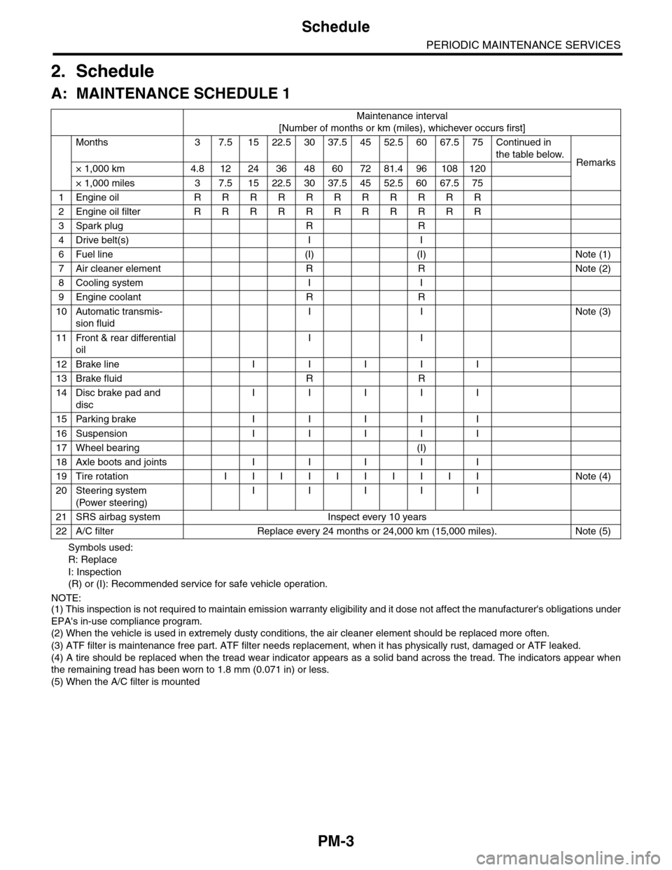
2. Schedule
A: MAINTENANCE SCHEDULE 1
Symbols used:
R: Replace
I: Inspection
(R) or (I): Recommended service for safe vehicle operation.
NOTE:(1) This inspection is not required to maintain emission warranty eligibility and it dose not affect the manufacturer's obligations under
EPA's in-use compliance program.
(2) When the vehicle is used in extremely dusty conditions, the air cleaner element should be replaced more often.
(3) ATF filter is maintenance free part. ATF filter needs replacement, when it has physically rust, damaged or ATF leaked.
(4) A tire should be replaced when the tread wear indicator appears as a solid band across the tread. The indicators appear when
the remaining tread has been worn to 1.8 mm (0.071 in) or less.
(5) When the A/C filter is mounted
Maintenance interval
[Number of months or km (miles), whichever occurs first]
Months 3 7.51522.53037.54552.56067.575Continued in
the table below.Remarks× 1,000 km 4.8 12 24 36 48 60 72 81.4 96 108 120
× 1,000 miles 3 7.5 15 22.5 30 37.5 45 52.5 60 67.5 75
1Engine oil R R R R R R R R R R R
2Engine oil filter R R R R R R R R R R R
3Spark plug R R
4Drive belt(s) I I
6Fuel line (I) (I) Note (1)
7Air cleaner element R R Note (2)
8Cooling system I I
9Engine coolant R R
10 Automatic transmis-
sion fluid
I I Note (3)
11 Front & rear differential
oil
I I
12 Brake line I I I I I
13 Brake fluid R R
14 Disc brake pad and
disc
I I I I I
15 Parking brake I I I I I
16 Suspension I I I I I
17 Wheel bearing (I)
18 Axle boots and joints I I I I I
19 Tire rotation I I I I I I I I I I Note (4)
20 Steering system
(Power steering)
I I I I I
21 SRS airbag system Inspect every 10 years
22 A/C filter Replace every 24 months or 24,000 km (15,000 miles). Note (5)
Page 1987 of 2453
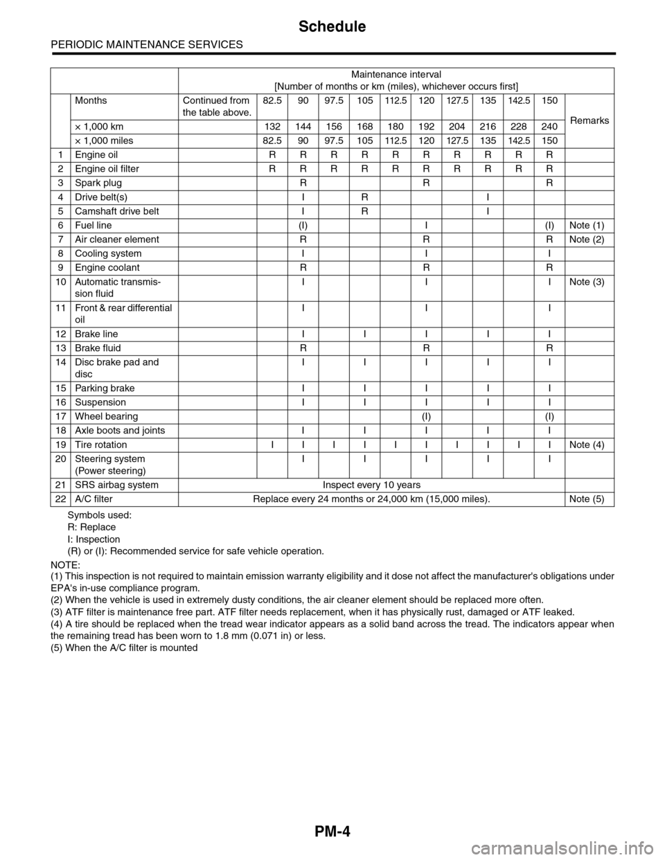
PM-4
Schedule
PERIODIC MAINTENANCE SERVICES
Symbols used:
R: Replace
I: Inspection
(R) or (I): Recommended service for safe vehicle operation.
NOTE:(1) This inspection is not required to maintain emission warranty eligibility and it dose not affect the manufacturer's obligations under
EPA's in-use compliance program.
(2) When the vehicle is used in extremely dusty conditions, the air cleaner element should be replaced more often.
(3) ATF filter is maintenance free part. ATF filter needs replacement, when it has physically rust, damaged or ATF leaked.
(4) A tire should be replaced when the tread wear indicator appears as a solid band across the tread. The indicators appear when
the remaining tread has been worn to 1.8 mm (0.071 in) or less.
(5) When the A/C filter is mounted
Maintenance interval
[Number of months or km (miles), whichever occurs first]
Months Continued from
the table above.
82.5 90 97.5 105112.5120127.5135142.5150
Remarks× 1,000 km 132 144 156 168 180 192 204 216 228 240
× 1,000 miles 82.5 90 97.5 105112.5120127.5135142.5150
1Engine oil R R R R R R R R R R
2Engine oil filter R R R R R R R R R R
3Spark plug R R R
4Drive belt(s) I R I
5Camshaft drive belt I R I
6Fuel line (I) I (I) Note (1)
7Air cleaner element R R R Note (2)
8Cooling system I I I
9Engine coolant R R R
10 Automatic transmis-
sion fluid
I I INote (3)
11 Front & rear differential
oil
I I I
12 Brake line I I I I I
13 Brake fluid R R R
14 Disc brake pad and
disc
I I I I I
15 Parking brake I I I I I
16 Suspension I I I I I
17 Wheel bearing (I) (I)
18 Axle boots and joints I I I I I
19 Tire rotation I I I I I I I I I I Note (4)
20 Steering system
(Power steering)
I I I I I
21 SRS airbag system Inspect every 10 years
22 A/C filter Replace every 24 months or 24,000 km (15,000 miles). Note (5)
Page 1993 of 2453
PM-10
V-belt
PERIODIC MAINTENANCE SERVICES
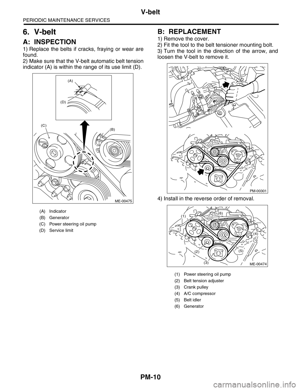
6. V-belt
A: INSPECTION
1) Replace the belts if cracks, fraying or wear are
found.
2) Make sure that the V-belt automatic belt tension
indicator (A) is within the range of its use limit (D).
B: REPLACEMENT
1) Remove the cover.
2) Fit the tool to the belt tensioner mounting bolt.
3) Turn the tool in the direction of the arrow, and
loosen the V-belt to remove it.
4) Install in the reverse order of removal.
(A) Indicator
(B) Generator
(C) Power steering oil pump
(D) Service limit
(B)
(A)
(D)
(C)
ME-00475
(1) Power steering oil pump
(2) Belt tension adjuster
(3) Crank pulley
(4) A/C compressor
(5) Belt idler
(6) Generator
PM-00301
(1)(6)
(4)
(5)(2)
(3)ME-00474