2009 SUBARU TRIBECA C0057
[x] Cancel search: C0057Page 458 of 2453

LAN(diag)-2
Basic Diagnostic Procedure
LAN SYSTEM (DIAGNOSTICS)
1. Basic Diagnostic Procedure
A: PROCEDURE
1. WITH SUBARU SELECT MONITOR
CAUTION:
•Subaru Select Monitor is required for reading DTC, performing diagnosis and reading current data.
•Remove foreign matter (dust, water, oil, etc.) from the body integrated unit connector during re-
moval and installation.
•For model with immobilizer, registration of immobilizer may be needed after the replacement of
controller etc. For detailed procedure, refer to the REGISTRATION MANUAL FOR IMMOBILIZER.
NOTE:
•To check harness for broken wires or short circuits, shake trouble spot or connector.
•Check List for Interview.
Step Check Yes No
1CHECK PRE-INSPECTION.
1) Ask the customer when and how the trou-
ble occurred using interview check list.
2) Check the display of communication error
display. (Combination meter, odo/trip meter)
Is the communication error dis-
played?
Go to step 3.Go to step 2.
2BASIC INSPECTION
Check the components which might affect
body control.
Is the component that might
influence the body control
problem normal?
Go to step 3.Repair or replace
each component.
3CHECK INDICATION OF DTC.
1) Read DTC of all systems.
CODE (DTC), OPERATION, Subaru Select
Monitor.>
NOTE:•The LAN system is for the overall vehicle, so
read the DTC of all systems.
•If the communication function of the Subaru
Select Monitor cannot be executed normally,
check the communication circuit.
TIALIZING IMPOSSIBLE, Diagnostic Proce-
dure with Diagnostic Trouble Code (DTC).>
2) Record all DTC.
Is a DTC other than CAN com-
munication displayed in the
output code?
ECU: P0600 TCU: P1718 VDC
CU: C0047 or C0057, etc.
Refer to the DTC
related table.
FUNCTION
CHECK, DTC
TA B L E , L i s t o f
Diagnostic Trou-
ble Code (DTC).>
Go to step 5.
Go to step 4.
4PERFORM GENERAL DIAGNOSTICS.
Inspect using “General Diagnostics Table”.
Is result of inspection OK? LAN system is nor-
mal.
Go to step 5.
5PERFORM DIAGNOSIS.
1) Correct the cause of trouble.
2) Perform the clear memory mode.
OPERATION, Subaru Select Monitor.>
3) Read the DTC.
OPERATION, Subaru Select Monitor.>
Is DTC displayed? Repeat step 5 until
DTC is not shown.
Finish the diagno-
sis.
Page 487 of 2453

LAN(diag)-31
List of Diagnostic Trouble Code (DTC)
LAN SYSTEM (DIAGNOSTICS)
1. DTC TABLE
NOTE:
When more than two DTC codes are recorded, referring to their combination will make it easy to identify the
possible cause. Refer to the list for typical examples.
DTC to Check Diagnostic Code that was displayed. Probable cause
Body inte-
grated unitECM TCMVDC/ABS
CM
Combina-
tion meter
display
B0100
ERROR, Diagnostic Procedure with
Diagnostic Trouble Code (DTC).>
B0100 P0600 P1718 — Er IU There could be a prob-
lem in the body inte-
grated unit.
B0221
MAL, Diagnostic Procedure with Diag-
nostic Trouble Code (DTC).>
B0221 — P1718 C0057 Er HC It is possible that the
ECM is faulty.
B0222
MAL, Diagnostic Procedure with Diag-
nostic Trouble Code (DTC).>
B0222 P0600 — C0057 Er HC It is possible that the
TCM is faulty.
B0223
ABNORMAL, Diagnostic Procedure
with Diagnostic Trouble Code (DTC).>
B0223 P0600 P1718 — Er HC It is possible that the
VDC/ABS CM is faulty.
B0321
DATA, Diagnostic Procedure with Diag-
nostic Trouble Code (DTC).>
B0321 — — — — It is possible that the
combination meter is
faulty.
B0313
ABNORMAL, Diagnostic Procedure
with Diagnostic Trouble Code (DTC).>
B0313 — — — — It is possible that the
navigation monitor or
MFD is faulty.
B0500
FUNCTION, Diagnostic Procedure with
Diagnostic Trouble Code (DTC).>
B0500 — — — — It is possible that the
keyless entry module
is faulty.
Page 508 of 2453

LAN(diag)-52
Diagnostic Procedure with Diagnostic Trouble Code (DTC)
LAN SYSTEM (DIAGNOSTICS)
10 CHECK ECM.
1) Disconnect the ECM connector (B136).
2) Measure the resistance between ECM con-
nector terminals.
Connector & terminal
(B136) No. 27 — No. 35:
Is the resistance between 115
— 125 Ω?
Repair or replace
the open circuit of
harness connec-
tor.
Open circuit in end
resistance of
ECM. Replace the
ECM.
Engine Control
Module (ECM).>
11 CHECK HARNESS.
1) Disconnect the body integrated unit con-
nector (B280).
2) Measure the resistance between body inte-
grated unit connector and chassis ground.
Connector & terminal
(B280) No. 20 — Chassis ground:
(B280) No. 30 — Chassis ground:
Is the resistance less than 10
Ω?
Repair or replace
the ground short
circuit of the har-
ness.
Go to step 12.
12 CHECK HARNESS.
1) Disconnect the body integrated unit con-
nector (B280).
2) Measure the voltage between body inte-
grated unit connector and chassis ground.
Connector & terminal
(B280) No. 20 (+) — Chassis ground (–):
(B280) No. 30 (+) — Chassis ground (–):
Is the voltage more than 6 V? Repair the short
circuit of harness
or replace har-
ness.
Go to step 13.
13 CHECK DTC.
Read the DTC of ECM using Subaru Select
Monitor.
(DTC).>
Is DTC other than “CAN com-
munication” displayed?
Pe r for m t h e d ia g -
nosis according to
DTC.
Go to step 14.
14 CHECK DTC.
Read the DTC of VDC CM using Subaru
Select Monitor.
OPERATION, Subaru Select Monitor.>
Is DTC other than “CAN com-
munication” or “C0057” dis-
played?
Pe r for m t h e d ia g -
nosis according to
DTC.
Go to step 15.
15 CHECK DTC.
Read the DTC of TCM using Subaru Select
Monitor.
Is DTC other than “CAN com-
munication” displayed?
Pe r for m t h e d ia g -
nosis according to
DTC.
Replace the body
integrated unit.
Integrated Unit.>
Step Check Yes No
Page 512 of 2453

LAN(diag)-56
Diagnostic Procedure with Diagnostic Trouble Code (DTC)
LAN SYSTEM (DIAGNOSTICS)
N: DTC B0221 CAN-HS ECM NO-RECEIVE DATA
DTC DETECTING CONDITION:
Defective ECM. (If error is in the main harness, DTC P0600 CAN communication link is input simultaneous-
ly.)
NOTE:
When more than two DTCs are displayed.
TROUBLE SYMPTOM:
•Malfunction indicator light illuminates.
•“Er HC” is displayed in odo/trip meter.
•P1718 (TCM) and C0057 (VDC CU) are output.
WIRING DIAGRAM:
VDCCM & H/U
B310
B20B30
BODY INTEGRATEDUNIT
B280B:
TCM
B54A:
23
B359
YAW R AT ESENSOR
34
20
B231
21
STEERING ANGLESENSOR
B231
1234
B54A:
12 7 8 9563410 11 1219 20 2113 14 15 16 17 1822 23 24
B136B310
B280B:
5467821931022 23111213141524 25 26 2716171828 29192021 30
ECM
B136
27
35
A3A4
TWISTED PAIR LINE
12345678910 11 12 13 14
15 16 17 18 19 2021 22 23 24 25 26 27 2829 30 31 32 33 3435 36 37 38 39403940
27 28394016101112131415252430
9871718192028212223293231
123456
2726333435
LAN00191
Page 515 of 2453

LAN(diag)-59
Diagnostic Procedure with Diagnostic Trouble Code (DTC)
LAN SYSTEM (DIAGNOSTICS)
O: DTC B0222 CAN-HS TCM NO-RECEIVE DATA
DTC DETECTING CONDITION:
TCM has error, harness between the main harness splice and TCM is open or shorted, connectors are not
connected securely, or the terminal has poor caulking.
NOTE:
When more than two DTCs are displayed.
TROUBLE SYMPTOM:
•Malfunction indicator light illuminates.
•“Er HC” is displayed in odo/trip meter.
•P0600 (ECM) and C0057 (VDC CM) are output.
WIRING DIAGRAM:
VDCCM & H/U
B310
B20B30
BODY INTEGRATEDUNIT
B280B:
TCM
B54A:
23
B359
YAW R AT ESENSOR
34
20
B231
21
STEERING ANGLESENSOR
B231
1234
B54A:
12 7 8 9563410 11 1219 20 2113 14 15 16 17 1822 23 24
B136B310
B280B:
5467821931022 23111213141524 25 26 2716171828 29192021 30
ECM
B136
27
35
A3A4
TWISTED PAIR LINE
12345678910 11 12 13 14
15 16 17 18 19 2021 22 23 24 25 26 27 2829 30 31 32 33 3435 36 37 38 39403940
27 28394016101112131415252430
9871718192028212223293231
123456
2726333435
LAN00191
Page 1028 of 2453

VDC(diag)-36
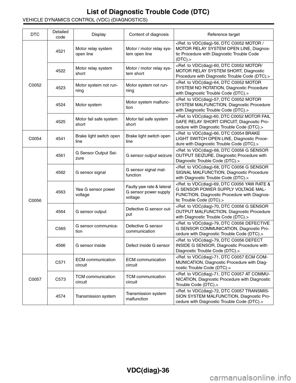
List of Diagnostic Trouble Code (DTC)
VEHICLE DYNAMICS CONTROL (VDC) (DIAGNOSTICS)
C0052
4521Motor relay system
open line
Motor / motor relay sys-
tem open line
tic Procedure with Diagnostic Trouble Code
(DTC).>
4522Motor relay system
short
Motor / motor relay sys-
tem short
Procedure with Diagnostic Trouble Code (DTC).>
4523Motor system not run-
ning
Motor system not run-
ning
with Diagnostic Trouble Code (DTC).>
4524 Motor systemMotor system malfunc-
tion
with Diagnostic Trouble Code (DTC).>
4525Motor fail safe system
short
Motor fail safe system
short
cedure with Diagnostic Trouble Code (DTC).>
C0054 4541Brake light switch open
line
Brake light switch open
line
dure with Diagnostic Trouble Code (DTC).>
C0056
4561G Sensor Output Sei-
zureG sensor output seizure
Diagnostic Trouble Code (DTC).>
4562 G sensor signalG sensor signal mal-
function
with Diagnostic Trouble Code (DTC).>
4563Ya w G s e n s o r p o w e r
voltage
Fau l t y yaw ra te & la t era l
G sensor power supply
voltage
FUNCTION, Diagnostic Procedure with Diagnos-
tic Trouble Code (DTC).>
4564 G sensor outputDefective G sensor out-
put
with Diagnostic Trouble Code (DTC).>
C565G sensor communica-
tion
Defective G sensor
communication
cedure with Diagnostic Trouble Code (DTC).>
4566 G sensor inside Defect inside G sensor
Diagnostic Trouble Code (DTC).>
C0057
C571ECM communication
circuit
ECM communication
circuit
nostic Trouble Code (DTC).>
C573TCM communication
circuit
TCM communication
circuit
Tr o u b l e C o d e ( D T C ) . >
4574 Transmission systemTr a n s m i s s i o n s y s t e m
malfunction
cedure with Diagnostic Trouble Code (DTC).>
DTCDetailed
codeDisplay Content of diagnosis Reference target
Page 1063 of 2453

VDC(diag)-71
Diagnostic Procedure with Diagnostic Trouble Code (DTC)
VEHICLE DYNAMICS CONTROL (VDC) (DIAGNOSTICS)
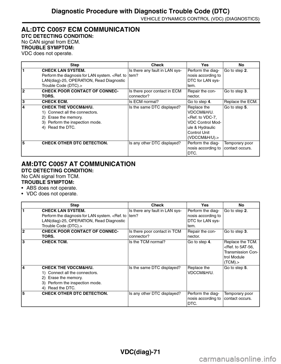
AL:DTC C0057 ECM COMMUNICATION
DTC DETECTING CONDITION:
No CAN signal from ECM.
TROUBLE SYMPTOM:
VDC does not operate.
AM:DTC C0057 AT COMMUNICATION
DTC DETECTING CONDITION:
No CAN signal from TCM.
TROUBLE SYMPTOM:
•ABS does not operate.
•VDC does not operate.
Step Check Yes No
1CHECK LAN SYSTEM.
Perfor m the diagnosis for LAN system.
Tr o u b l e C o d e ( D T C ) . >
Is there any fault in LAN sys-
tem?
Pe r for m t h e d ia g -
nosis according to
DTC for LAN sys-
tem.
Go to step 2.
2CHECK POOR CONTACT OF CONNEC-
TORS.
Is there poor contact in ECM
connector?
Repair the con-
nector.
Go to step 3.
3CHECK ECM.Is ECM normal? Go to step 4.Replace the ECM.
4CHECK THE VDCCM&H/U.
1) Connect all the connectors.
2) Erase the memory.
3) Perform the inspection mode.
4) Read the DTC.
Is the same DTC displayed? Replace the
VDCCM&H/U.
ule & Hydraulic
Control Unit
(VDCCM&H/U).>
Go to step 5.
5CHECK OTHER DTC DETECTION.Is any other DTC displayed? Perform the diag-
nosis according to
DTC.
Te m p o r a r y p o o r
contact occurs.
Step Check Yes No
1CHECK LAN SYSTEM.
Perfor m the diagnosis for LAN system.
Tr o u b l e C o d e ( D T C ) . >
Is there any fault in LAN sys-
tem?
Pe r for m t h e d ia g -
nosis according to
DTC for LAN sys-
tem.
Go to step 2.
2CHECK POOR CONTACT OF CONNEC-
TORS.
Is there poor contact in TCM
connector?
Repair the con-
nector.
Go to step 3.
3CHECK TCM.Is the TCM normal? Go to step 4.Replace the TCM.
trol Module
(TCM).>
4CHECK THE VDCCM&H/U.
1) Connect all the connectors.
2) Erase the memory.
3) Perform the inspection mode.
4) Read the DTC.
Is the same DTC displayed? Replace the
VDCCM&H/U.
Go to step 5.
5CHECK OTHER DTC DETECTION.Is any other DTC displayed? Perform the diag-
nosis according to
DTC.
Te m p o r a r y p o o r
contact occurs.
Page 1064 of 2453

VDC(diag)-72
Diagnostic Procedure with Diagnostic Trouble Code (DTC)
VEHICLE DYNAMICS CONTROL (VDC) (DIAGNOSTICS)
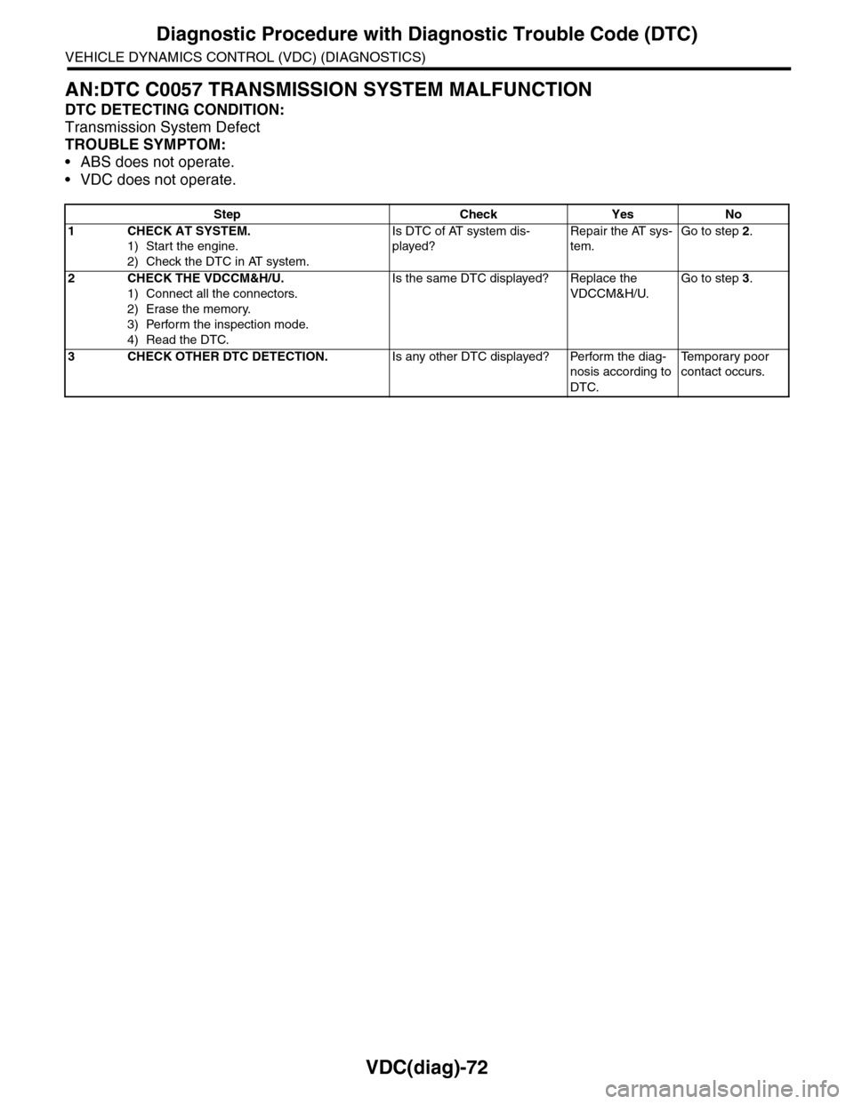
AN:DTC C0057 TRANSMISSION SYSTEM MALFUNCTION
DTC DETECTING CONDITION:
Transmission System Defect
TROUBLE SYMPTOM:
•ABS does not operate.
•VDC does not operate.
Step Check Yes No
1CHECK AT SYSTEM.
1) Start the engine.
2) Check the DTC in AT system.
Is DTC of AT system dis-
played?
Repair the AT sys-
tem.
Go to step 2.
2CHECK THE VDCCM&H/U.
1) Connect all the connectors.
2) Erase the memory.
3) Perform the inspection mode.
4) Read the DTC.
Is the same DTC displayed? Replace the
VDCCM&H/U.
Go to step 3.
3CHECK OTHER DTC DETECTION.Is any other DTC displayed? Perform the diag-
nosis according to
DTC.
Te m p o r a r y p o o r
contact occurs.