2009 SUBARU TRIBECA door lock
[x] Cancel search: door lockPage 235 of 2453

EB-16
Front Door
EXTERIOR BODY PANELS
4. Front Door
A: REMOVAL
1) Disconnect the ground cable from battery.
2) Remove the front door trim.
3) Remove the outer mirror assembly.
4) Remove the front door speaker.
5) Remove the sealing cover.
6) Remove the front door glass.
7) Remove the door sash, and remove the front
door regulator and motor assemblies.
bly.>
8) Remove the front inner remote.
9) Remove the front door latch assembly.
Lock Actuator Assembly.>
10) Remove the front outer handle.
11) Remove the front door weather strip.
NOTE:
If the weather strip clip is removed with excessive
force, the weather strip may be damaged. Be sure
to use clip remover to remove.
12) Remove the bolts and nuts to remove the door
checker.
13) Remove the instrument panel lower cover or
glove box lower cover.
14) Disconnect the connector of door harness from
body harness.
15) Put a wooden block on jack and place jack un-
der the front door. Support the door with a jack to
protect it from damage.
16) Remove the door-side bolts for upper and low-
er hinges to remove front door panel.
17) Remove the door hinge from vehicle.
EB-00141
EB-00154
EB-00151
EB-00013
EB-00015
Page 236 of 2453
EB-17
Front Door
EXTERIOR BODY PANELS
B: INSTALLATION
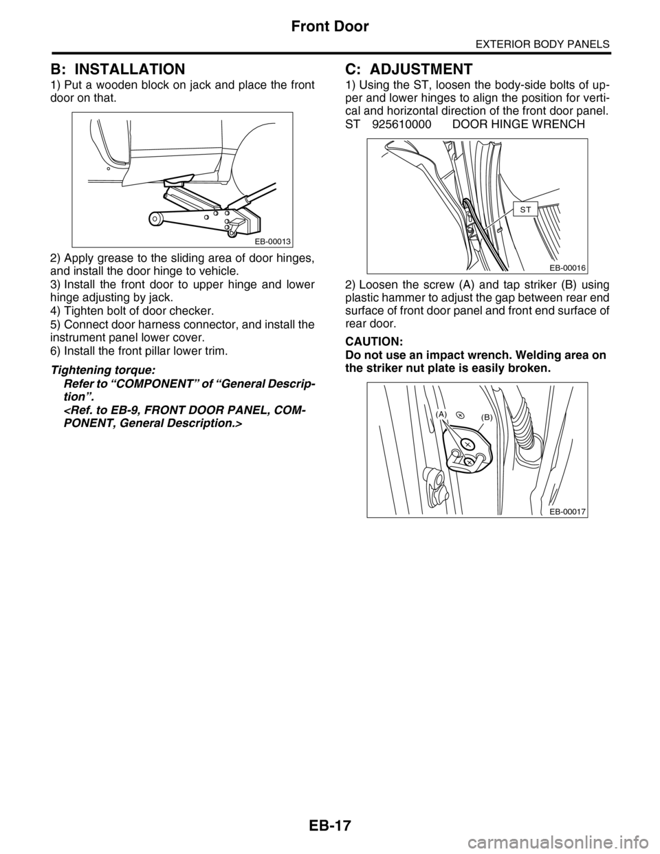
1) Put a wooden block on jack and place the front
door on that.
2) Apply grease to the sliding area of door hinges,
and install the door hinge to vehicle.
3) Install the front door to upper hinge and lower
hinge adjusting by jack.
4) Tighten bolt of door checker.
5) Connect door harness connector, and install the
instrument panel lower cover.
6) Install the front pillar lower trim.
Tightening torque:
Refer to “COMPONENT” of “General Descrip-
tion”.
C: ADJUSTMENT
1) Using the ST, loosen the body-side bolts of up-
per and lower hinges to align the position for verti-
cal and horizontal direction of the front door panel.
ST 925610000 DOOR HINGE WRENCH
2) Loosen the screw (A) and tap striker (B) using
plastic hammer to adjust the gap between rear end
surface of front door panel and front end surface of
rear door.
CAUTION:
Do not use an impact wrench. Welding area on
the striker nut plate is easily broken.
EB-00013
EB-00016
ST
EB-00017
(B)(A)
Page 238 of 2453
EB-19
Rear Door
EXTERIOR BODY PANELS
6. Rear Door
A: REMOVAL
1) Disconnect the ground cable from battery.
2) Remove the rear door trim.
3) Remove the rear speaker.
4) Remove the sealing cover.
5) Remove the rear door glass.
6) Remove the door sash and rear door regulator
and motor assemblies.
7) Remove the rear inner remote.
8) Remove the rear door latch.
Assembly.>
9) Remove the rear outer handle.
10) Remove the rear door inner weather strip.
NOTE:
If the weather strip clip is removed with excessive
force, the weather strip may be damaged. Be sure
to use clip remover to remove.
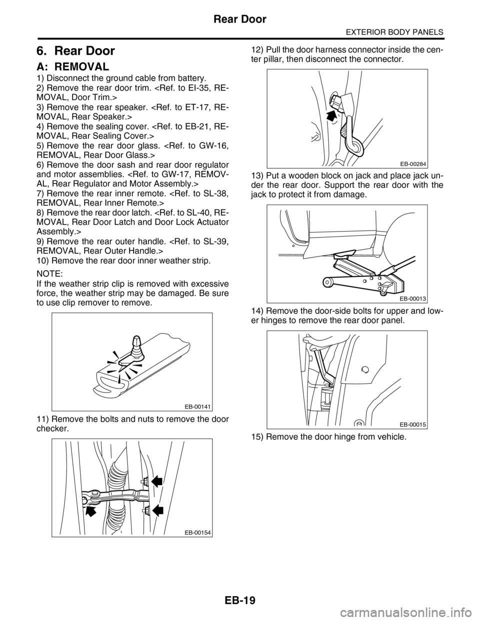
11) Remove the bolts and nuts to remove the door
checker.
12) Pull the door harness connector inside the cen-
ter pillar, then disconnect the connector.
13) Put a wooden block on jack and place jack un-
der the rear door. Support the rear door with the
jack to protect it from damage.
14) Remove the door-side bolts for upper and low-
er hinges to remove the rear door panel.
15) Remove the door hinge from vehicle.
EB-00141
EB-00154
EB-00284
EB-00013
EB-00015
Page 239 of 2453
EB-20
Rear Door
EXTERIOR BODY PANELS
B: INSTALLATION
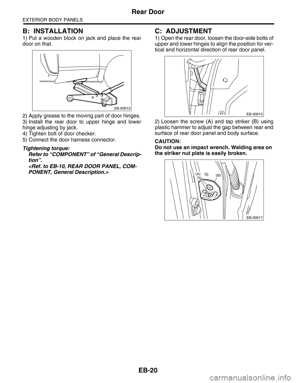
1) Put a wooden block on jack and place the rear
door on that.
2) Apply grease to the moving part of door hinges.
3) Install the rear door to upper hinge and lower
hinge adjusting by jack.
4) Tighten bolt of door checker.
5) Connect the door harness connector.
Tightening torque:
Refer to “COMPONENT” of “General Descrip-
tion”.
C: ADJUSTMENT
1) Open the rear door, loosen the door-side bolts of
upper and lower hinges to align the position for ver-
tical and horizontal direction of rear door panel.
2) Loosen the screw (A) and tap striker (B) using
plastic hammer to adjust the gap between rear end
surface of rear door panel and body surface.
CAUTION:
Do not use an impact wrench. Welding area on
the striker nut plate is easily broken.
EB-00013
EB-00015
EB-00017
(B)(A)
Page 460 of 2453
LAN(diag)-4
Check List for Interview
LAN SYSTEM (DIAGNOSTICS)
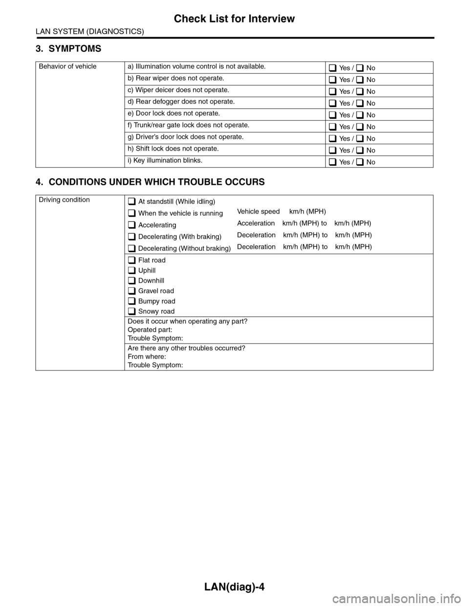
3. SYMPTOMS
4. CONDITIONS UNDER WHICH TROUBLE OCCURS
Behavior of vehicle a) Illumination volume control is not available. Yes / No
b) Rear wiper does not operate. Yes / No
c) Wiper deicer does not operate. Yes / No
d) Rear defogger does not operate. Yes / No
e) Door lock does not operate. Yes / No
f) Trunk/rear gate lock does not operate. Yes / No
g) Driver’s door lock does not operate. Yes / No
h) Shift lock does not operate. Yes / No
i) Key illumination blinks. Yes / No
Driving condition At standstill (While idling)
When the vehicle is runningVe h i c l e s p e e d k m / h ( M P H )
AcceleratingAcceleration km/h (MPH) to km/h (MPH)
Decelerating (With braking)Deceleration km/h (MPH) to km/h (MPH)
Decelerating (Without braking)Deceleration km/h (MPH) to km/h (MPH)
Flat road
Uphill
Downhill
Gravel road
Bumpy road
Snowy road
Does it occur when operating any part?
Operated part:
Tr o u b l e S y m p t o m :
Are there any other troubles occurred?
Fr o m wh er e :
Tr o u b l e S y m p t o m :
Page 465 of 2453

LAN(diag)-9
Control Module I/O Signal
LAN SYSTEM (DIAGNOSTICS)
5. Control Module I/O Signal
A: ELECTRICAL SPECIFICATION
DescriptionConnec-
tor No.
Te r m i n a l
No.
Signal (V)
NoteIgnition switch ON
(Engine OFF)
System control power
supplyB281 C2 10 — 13 V Always
Backup power supply B280 B7 10 — 13 V Always
Ignition power supply i84 A1 10 — 13 V Ignition ON
ACC power supply i84 A24 10 — 13 V AC C ON
Ground
i84 A21
0 V AlwaysB281 C9
B281 C8
B280 B22
Key war ning switch B281 C7 10 — 13 V When ignition key inser ted
Stop light switch B281 C23 10 — 13 V When brake pedal depressed
Illumination control switch
(Bright switch)i84 A30 10 — 13 V (at dimmer ON)Cancel the extinction of the clock and
audio illumination
Illumination control switch i84 A30 10 — 13 V (at dimmer ON) Extinct the clock and audio illumination
Illumination volume (Vi1) i84 A10 4.5 — 5.5 V Small light ON
Illumination volume (Vi2) i84 A2 0.5 — 4.5 V —
Illumination volume (Vi3) i84 A25 0 V Ground circuit
Illumination output i84 A5 10 — 13 V Small light ON
Fr o nt fog li g ht in p ut B 28 1 C1 7 1 0 — 1 3 V Fr o nt fo g l i gh t ON
Door switch input Driver’s
seati84 A19 Less than 1 V (10 — 13 V at OFF) Driver’s door open (ON)
Door switch input Passen-
ger’s seati84 A32 Less than 1 V (10 — 13 V at OFF) Passenger’s door open (ON)
Door switch input Rear RH
seati84 A18 Less than 1 V (10 — 13 V at OFF) Rear RH door open (ON)
Door switch input Rear LH
seati84 A31 Less than 1 V (10 — 13 V at OFF) Rear LH door open (ON)
Door switch
Tr u n k / R e a r g a t ei84 A17 Less than 1 V (10 — 13 V at OFF) Trunk/Rear gate open (ON)
Manual switch (LOCK) i84 A15 Less than 1 ΩDoor lock switch ON
CS-00273
71928
61827
51741626152514241312231122
3102921
1820
B281side
72030
619291828
51741627152614132512241123
3102922
1821
B280side
82335
722342162033
51932183117301615291428
41327
312261121025
1924
i84side
Page 466 of 2453

LAN(diag)-10
Control Module I/O Signal
LAN SYSTEM (DIAGNOSTICS)
Manual switch (UNLOCK) i84 A29 Less than 1 ΩDoor unlock switch ON
Door lock power supply i84 A34 10 — 13 V Always
All door lock output i84 A7 10 — 13 V Manual lock switch, door key switch ON
Driver’s door UNLOCK
outputi84 A23 10 — 13 V Driver’s seat unlock signal ON
All door UNLOCK output i84 A8 10 — 13 V ALL door unlock signals ON
Rear gate UNLOCK out-
puti84 A22 10 — 13 VWhen rear gate release switch ON with
all seats unlocked
Rear gate release switch B281 C22 0 V Rear gate release switch ON
Key/shift lock power sup-
plyB281 C1 10 — 13 V Always
Shift lock output B280 B6 10 — 13 VIgnition switch ON, shift position “P”
range, foot brake ON (Only AT)
Key locking output B280 B5 10 — 13 VOther than “P” range, ignition switch
ON
Wiper deicer switch i84 A14 0 V Wiper deicer switch ON
Wiper deicer relay output B280 B14 0 V Wiper deicer relay ON
Rear defogger switch i84 A28 0 V Rear defogger switch ON
Rear defogger relay out-
putB281 B16 0 V Rear defogger relay ON
Shift switch (ON) B281 C26 0 V At Manual mode
Shift switch (UP) B281 C15 0 V At Manual mode UP
Shift switch (DOWN) B281 C25 0 V At Manual mode DOWN
Shift button switch B281 C24 0 VWhen shift lever release button is oper-
ated
P range switch B281 C13 0 V Shift range P position
Impact sensor B281 C5 8 V or moreImpact sensor ON (Model with impact
sensor)
Fuel level sensor B281 C19 0 — 102.3 Ω
Resistance differs according to the fuel
level (displays resistance combining
level gauge main and sub)
Ambient temperature sen-
sor
B281 C3 0.5 — 4.5 V SIG
B281 C10 0 V GND
Seat belt switch (driver’s
seat)i84 A4 0 V When driver’s seat belt is worn
Seat belt switch (Passen-
ger’s seat)i84 A13 0 V When passenger’s seat belt is worn
Seat belt warning light
(driver’s seat)i84 A20 0 V When driver’s seat belt is worn
Seat belt warning light
(Passenger’s seat)B280 C27 0 V When passenger’s seat belt is worn
Rear wiper switch (ON) B281 C6 0 V Rear wiper switch ON
Rear wiper switch (INT) B281 C18 0 V Rear wiper switch ON
Rear washer switch B281 C27 0 V Rear washer switch ON
Rear wiper power supply B280 B21 10 — 13 V Ignition switch ON
Rear wiper ON output B280 B1 10 — 13 V Rear wiper switch ON
Rear wiper return B280B8 0 VAt wiper reversingB1 — B8 0 V
Room lamp output B280 B3 0 VWhen LOCK, UNLOCK with keyless
entry
Map lamp output B280D2 0 V When using map lamp
D9 0 V When using map lamp
DescriptionConnec-
tor No.
Te r m i n a l
No.
Signal (V)
NoteIgnition switch ON
(Engine OFF)
Page 470 of 2453
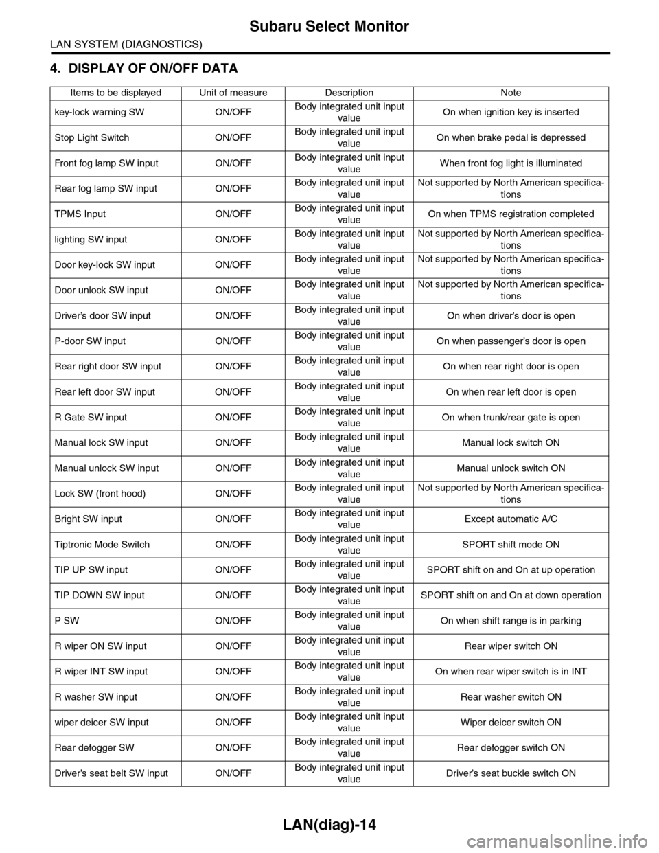
LAN(diag)-14
Subaru Select Monitor
LAN SYSTEM (DIAGNOSTICS)
4. DISPLAY OF ON/OFF DATA
Items to be displayed Unit of measure Description Note
key-lock warning SW ON/OFFBody integrated unit input
valueOn when ignition key is inserted
Stop Light Switch ON/OFFBody integrated unit input
valueOn when brake pedal is depressed
Fr o nt fog la mp S W i n pu t O N/O FFBody integrated unit input
valueWhen front fog light is illuminated
Rear fog lamp SW input ON/OFFBody integrated unit input
value
Not supported by North American specifica-
tions
TPMS Input ON/OFFBody integrated unit input
valueOn when TPMS registration completed
lighting SW input ON/OFFBody integrated unit input
value
Not supported by North American specifica-
tions
Door key-lock SW input ON/OFFBody integrated unit input
value
Not supported by North American specifica-
tions
Door unlock SW input ON/OFFBody integrated unit input
value
Not supported by North American specifica-
tions
Driver’s door SW input ON/OFFBody integrated unit input
valueOn when driver’s door is open
P-door SW input ON/OFFBody integrated unit input
valueOn when passenger’s door is open
Rear right door SW input ON/OFFBody integrated unit input
valueOn when rear right door is open
Rear left door SW input ON/OFFBody integrated unit input
valueOn when rear left door is open
R Gate SW input ON/OFFBody integrated unit input
valueOn when trunk/rear gate is open
Manual lock SW input ON/OFFBody integrated unit input
valueManual lock switch ON
Manual unlock SW input ON/OFFBody integrated unit input
valueManual unlock switch ON
Lock SW (front hood) ON/OFFBody integrated unit input
value
Not supported by North American specifica-
tions
Bright SW input ON/OFFBody integrated unit input
valueExcept automatic A/C
Tiptronic Mode Switch ON/OFFBody integrated unit input
valueSPORT shift mode ON
TIP UP SW input ON/OFFBody integrated unit input
valueSPORT shift on and On at up operation
TIP DOWN SW input ON/OFFBody integrated unit input
valueSPORT shift on and On at down operation
P SW ON/OFFBody integrated unit input
valueOn when shift range is in parking
R wiper ON SW input ON/OFFBody integrated unit input
valueRear wiper switch ON
R wiper INT SW input ON/OFFBody integrated unit input
valueOn when rear wiper switch is in INT
R washer SW input ON/OFFBody integrated unit input
valueRear washer switch ON
wiper deicer SW input ON/OFFBody integrated unit input
valueWiper deicer switch ON
Rear defogger SW ON/OFFBody integrated unit input
valueRear defogger switch ON
Driver’s seat belt SW input ON/OFFBody integrated unit input
valueDriver’s seat buckle switch ON