2009 SUBARU TRIBECA coolant temperature sensor
[x] Cancel search: coolant temperature sensorPage 391 of 2453

AC(diag)-14
Diagnostic Chart for Self-diagnosis
HVAC SYSTEM (AUTO A/C) (DIAGNOSTICS)
4. SENSOR CHECK TABLE
NOTE:
When the sunload sensor check is performed indoors or in the shade, it could be diagnosed as having an
open circuit. Always check the sunload sensor with the sun shining on it.
*1: “AUTO” display does not blink when past malfunction occurred. Past malfunction means that abnormal signals were contin-
uously input for a certain time in the past.
*2: Present malfunction only is displayed for sunload sensor open circuit.
5. OPERATING MODE TABLE
*Same opening angle for both driver’s and passenger’s side
Display screen (Malfunction at
present) *1Sensor Trouble contents
21/AUTO BlinkIn-vehicle sensorOpen
–21/AUTO BlinkShort
22/AUTO Blink Ambient sensor Sensor trouble or communication malfunction
23/AUTO BlinkEvaporator sensorOpen
–23/AUTO BlinkShort
24/AUTO Blink Engine coolant temperature sensor Sensor trouble or communication malfunction
25 BlinkSunload sensorOpen *2
–25/AUTO BlinkShort
26/AUTO BlinkDriver's side air mix door actuator
potentiometer
COOL
27/AUTO BlinkHOT
–26/AUTO BlinkPassenger’s side air mix door actua-
tor potentiometer
COOL
–27/AUTO BlinkHOT
28/AUTO BlinkMode door actuator potentiometerFA C E
29/AUTO BlinkDEF
41/AUTO BlinkSeat heater thermistor (Driver’s
side)
Open
–41/AUTO BlinkShort
42/AUTO BlinkSeat heater thermistor (Passenger’s
side)
Open
–42/AUTO BlinkShort
20 Blink When all conditions are normal
Display screenFRESH/RECIRC
doorMode door Air mix door* Blower fanA/C compressor (Mag-
net clutch)
31 FRESH FACE Maximum cool LO OFF
32 RECIRC FACE Maximum cool LO ON
33 RECIRC FACE Maximum cool M1 ON
34 FRESH B/L 50% M1 ON
35 FRESH HEAT 50% M1 ON
36 FRESH HEAT Maximum hot M3 ON
37 FRESH D/H Maximum hot M3 ON
38 FRESH DEF Maximum hot HI ON
Page 446 of 2453

IDI-7
Combination Meter System
INSTRUMENTATION/DRIVER INFO
3. SYMPTOM CHART
CAUTION:
When measuring the voltage and resistance of each control module or sensor, use a tapered pin with
a diameter of less than 0.64 mm (0.025 in) in order to avoid poor contact. Do not insert the pin more
than 2 mm (0.08 in).
4. CHECK POWER SUPPLY AND GROUND CIRCUIT
Symptom Repair order Note
Combination meter assembly does not
operate.
1. Power supply
2. Ground circuit
3. Combination meter
Combination Meter System.>
Speedometer does not operate. 1. VDCCM
2. Harness
3. Combination meter
tem.>
Ta c h o m e t e r d o e s n o t o p e r a t e . 1 . E C M
2. Harness
3. Combination meter
Combination Meter System.>
Fuel gauge does not operate. 1. Communication circuit
2. Fuel level sensor
3. Harness
4. Combination meter
Meter System.>
Engine coolant temperature gauge does
not operate.
1. Communication circuit
2. Engine coolant temperature sensor
3. Harness
4. Combination meter
INSPECTION, Combination Meter Sys-
tem.>
Error display is shown on the odo/trip
meter.
Communication circuit
nation Meter System.>
Step Check Yes No
1CHECK POWER SUPPLY FOR COMBINA-
TION METER.
1) Remove the combination meter.
2) Disconnect the combination meter harness
connector.
3) Turn the ignition switch to ON.
4) Measure the voltage between combination
meter connector and chassis ground.
Connector & terminal
(i10) No. 3, 4 (+) — Chassis ground (–):
Is the voltage more than 10 V? Go to step 2.Check the harness
for open or shor t
between the igni-
tion switch and
combination
meter.
2CHECK POWER SUPPLY FOR COMBINA-
TION METER.
Measure the voltage between combination
meter connector and chassis ground.
Connector & terminal
(i10) No. 1, 2 (+) — Chassis ground (–):
Is the voltage more than 10 V? Go to step 3.Check the harness
for open or shor t
between the fuse
and combination
meter.
3CHECK GROUND CIRCUIT OF COMBINA-
TION METER.
1) Turn the ignition switch to OFF.
2) Measure the resistance of harness
between combination meter connector and
chassis ground.
Connector & terminal
(i10) No. 15, 16 — Chassis ground:
Is the resistance less than 10
Ω?
Replace the meter
case assembly.
Repair the wiring
harness.
Page 449 of 2453

IDI-10
Combination Meter System
INSTRUMENTATION/DRIVER INFO
8. CHECK ENGINE COOLANT TEMPERATURE SENSOR.
9. COMMUNICATION ERROR DISPLAY
When the following error code is displayed in the
odo/trip meter, inspect the communication circuit
since the communication malfunction is generated
between each control module.
10.DTC DISPLAY MODE
When DTC display mode is operated, {ECM}, {TCM} is displayed repeatedly in this order by pressing the trip
knob. DTC is displayed in the following table according to type of control module, receiving DTC, DTC de-
tected, No DTC. If CAN communication has some trouble, “-----” is displayed.
Step Check Yes No
1CHECK COMMUNICATION ERROR DIS-
PLAY.
1) Turn the ignition switch to ON.
2) Check that the error code is displayed in
odo/trip meter.
Is the error code “Er xx” dis-
played in odo/trip meter?
Check the commu-
nication circuit.
TION ERROR
DISPLAY,
INSPECTION,
Combination
Meter System.>
Go to step 2.
2CHECK ENGINE COOLANT TEMPERATURE
SENSOR.
Check the engine coolant temperature sensor.
Is the engine coolant tempera-
ture sensor OK?
Replace the meter
case assembly.
Replace the
engine coolant
temperature sen-
sor.
IDI00188
Error code Description
Er IUMalfunction in integrated
module
Er ––
Simultaneous malfunction of
high/low speed CAN com-
munication
Er HCHigh speed CAN communi-
cation malfunction
Er LCMalfunction of low-speed
CAN communication
Er EGEGI Communication mal-
function
Er TCTCM Communication mal-
function
Er AbVDCCM communication
malfunction
Er SP
VDCCM DTC information
and vehicle speed pulse
malfunction
Er SSWheel speed data malfunc-
tion
Er bbVa c u u m p u m p s y s t e m m a l -
function
Control module Condition Display
ECM
Receiving DTC Trip “A” + “P (Blink)”
DTC detected Trip “A” + “P xxxx”
No DTC Trip “A” + “P ----”
TCM
Receiving DTC Trip “B” + “P (Blink)”
DTC detected Trip “B” + “P xxxx”
No DTC Trip “B” + “P ----”
When CAN communication error
is occurred—“-----”
Page 469 of 2453
![SUBARU TRIBECA 2009 1.G Service Workshop Manual LAN(diag)-13
Subaru Select Monitor
LAN SYSTEM (DIAGNOSTICS)
2. READ CURRENT DATA
1) On the «Main Menu» display screen, select the {Each System Check} and press the [YES] key.
2) On the «System Sele SUBARU TRIBECA 2009 1.G Service Workshop Manual LAN(diag)-13
Subaru Select Monitor
LAN SYSTEM (DIAGNOSTICS)
2. READ CURRENT DATA
1) On the «Main Menu» display screen, select the {Each System Check} and press the [YES] key.
2) On the «System Sele](/manual-img/17/7322/w960_7322-468.png)
LAN(diag)-13
Subaru Select Monitor
LAN SYSTEM (DIAGNOSTICS)
2. READ CURRENT DATA
1) On the «Main Menu» display screen, select the {Each System Check} and press the [YES] key.
2) On the «System Selection Menu» display screen, select the {Integ. Unit mode} and press the [YES] key.
3) On the «Integ. unit mode failure diag» display screen, select the {Current Data Display & Save} and press
the [YES] key.
4) On the «Current Data Display & Save» display screen, select the {12 Data Display} and press the [YES]
key.
5) Using the scroll key, scroll the display screen up or down until the desired data is shown.
•A support list contains both of analog and digital data, and they are shown in the following table.
3. DISPLAY OF ANALOG DATA
Items to be displayed Unit of measure Description Note
BATT Voltage (Control) 10 — 15 VBody integrated unit input
valueAlways
BATT Voltage (BACK UP) 10 — 15 VBody integrated unit input
valueAlways
IG power supply voltage 10 — 15 VBody integrated unit input
valueIgnition switch ON
ACC voltage 10 — 15 VBody integrated unit input
valueIgnition switch ACC
Illumination VR voltage 0 — 5 VBody integrated unit out-
put valueSmall light switch ON
Illumi. output d-ratio 0 — 100%Body integrated unit input
value
Small light ON
Illumination volume is other than bright.
Ambient temp sensor V 0 — 5 VBody integrated unit out-
put valueIgnition switch ON
Ambient temperature –40 — 87.5°CBody integrated unit out-
put valueIgnition switch ON
Fuel level voltage 0 — 8 VBody integrated unit input
valueIgnition switch ON
Fuel level resistance 0 — 102.3 ΩBody integrated unit input
valueIgnition switch ON
key-lock solenoid V 6 — 12 VBody integrated unit out-
put value
Other than parking range
Ignition ON
number of regist. 0 — 4 Key No. to register
Fr o nt W he e l S p ee d km / h C A N d a t a i np u t val u e R ec ep t io n f r o m V DC u ni t
VDC/ABS latest f-codeDTC display (Tempo-
rarily)CAN data input value
It is normal when DTC is not been input
even if this code is displayed.
Reception from VDC
Blower fan steps 0 — 2 levels CAN data input value0: OFF, 1: Low, 2: 2 levels or more
Reception from air conditioner ECM
Fuel level resistance2 0 — 102.3 ΩCAN data output value Reception from body integrated unit
Fuel consumption cc/s CAN data input valueReception from ECM and transmission to
center monitor
Coolant Temp. 40 — 130°C CAN data input value Reception from ECM
Ve h i c l e l a t e r a l Gm/s2CAN data input value Reception from VDC unit
SPORT Shift Stages 0 — 7 levels CAN data input value
(0: Light OFF; 1 — 5: Gear display; 6: Fail; 7:
AT F t e m p e r a t u r e H i g h / L o w )
Reception from TCM
Shift Position 0 — 7 levels CAN data input value
0: 1; 1: 2; 2: 3; 3: 4; 4: D; 5: N; 6: R; 7: P shift
position (There is no 8 input.)
Reception from TCM
Off delay timeOFF, Short, Normal,
Long
Body integrated unit set-
ting itemsCustomize setting
Auto lock time20, 30, 40, 50, 60 sec-
onds
Body integrated unit set-
ting itemsCustomize setting
Page 1018 of 2453

VDC(diag)-26
Warning Light Illumination Pattern
VEHICLE DYNAMICS CONTROL (VDC) (DIAGNOSTICS)
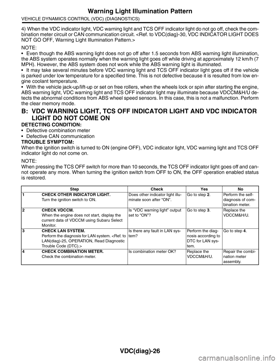
4) When the VDC indicator light, VDC warning light and TCS OFF indicator light do not go off, check the com-
bination meter circuit or CAN communication circuit.
NOTE:
•Even though the ABS warning light does not go off after 1.5 seconds from ABS warning light illumination,
the ABS system operates normally when the warning light goes off while driving at approximately 12 km/h (7
MPH). However, the ABS system does not work while the ABS warning light is illuminated.
•It may take several minutes before VDC warning light and TCS OFF indicator light goes off if the vehicle
is parked under low temperature for a specified time. This is not defective because it is resulted from low en-
gine coolant temperature.
•With the vehicle jack-up/lift-up or set on free rollers, when the wheels lock or spin after starting the engine,
ABS warning light, VDC warning light and TCS OFF indicator light may illuminate because VDCCM&H/U de-
tects the abnormal conditions from ABS wheel speed sensors. In this case, this is not a malfunction. Perform
the clear memory mode.
B: VDC WARNING LIGHT, TCS OFF INDICATOR LIGHT AND VDC INDICATOR
LIGHT DO NOT COME ON
DETECTING CONDITION:
•Defective combination meter
•Defective CAN communication
TROUBLE SYMPTOM:
When the ignition switch is turned to ON (engine OFF), VDC indicator light, VDC warning light and TCS OFF
indicator light do not come on.
NOTE:
When pressing the TCS OFF switch for more than 10 seconds, the TCS OFF indicator light goes off and can-
not operate any more. When turning the ignition switch from OFF to ON, the OFF operation enabled status
is restored.
Step Check Yes No
1CHECK OTHER INDICATOR LIGHT.
Tu r n t h e i g n i t i o n s w i t c h t o O N .
Does other indicator light illu-
minate soon after “ON”.
Go to step 2.Perform the self-
diagnosis of com-
bination meter.
2CHECK VDCCM.
When the engine does not start, display the
current data of VDCCM using Subaru Select
Monitor.
Is “VDC warning light” output
set to “ON”?
Go to step 3.Replace the
VDCCM&H/U.
3CHECK LAN SYSTEM.
Perfor m the diagnosis for LAN system.
Tr o u b l e C o d e ( D T C ) . >
Is there any fault in LAN sys-
tem?
Pe r for m t h e d ia g -
nosis according to
DTC for LAN sys-
tem.
Go to step 4.
4CHECK COMBINATION METER.
Check the combination meter.
Is combination meter OK? Replace the
VDCCM&H/U.
Repair the combi-
nation meter
assembly.
Page 1149 of 2453

CO(H6DO)-30
Engine Cooling System Trouble in General
COOLING
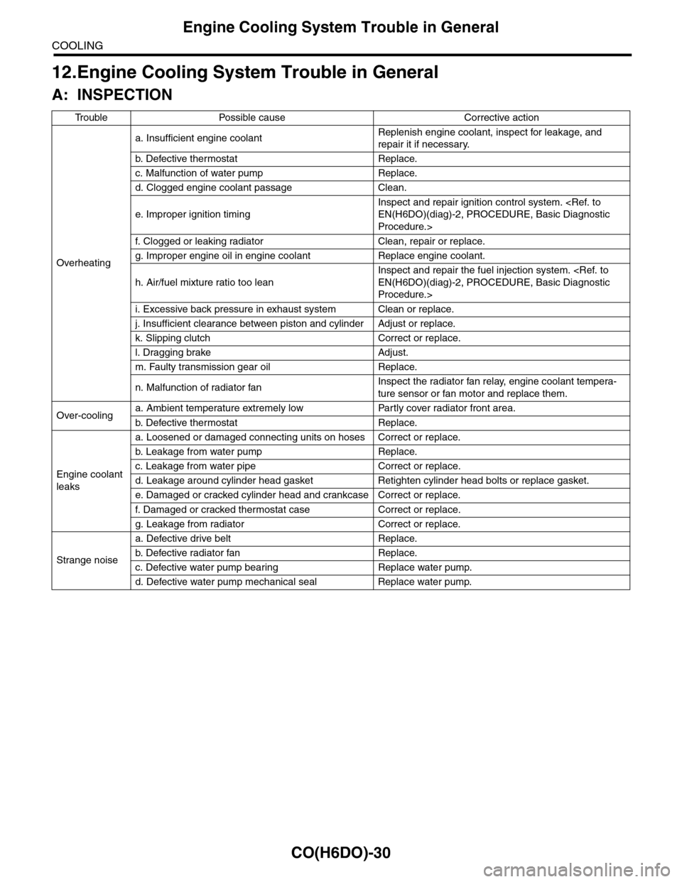
12.Engine Cooling System Trouble in General
A: INSPECTION
Tr o u b l e P o s s i b l e c a u s e C o r r e c t i v e a c t i o n
Overheating
a. Insufficient engine coolantReplenish engine coolant, inspect for leakage, and
repair it if necessary.
b. De fe c ti ve t he r mo st a t Rep la c e.
c. Malfunction of water pump Replace.
d. Clogged engine coolant passage Clean.
e. Improper ignition timing
Inspect and repair ignition control system.
Procedure.>
f. Clogged or leaking radiator Clean, repair or replace.
g. Improper engine oil in engine coolant Replace engine coolant.
h. Air/fuel mixture ratio too lean
Inspect and repair the fuel injection system.
Procedure.>
i. Excessive back pressure in exhaust system Clean or replace.
j. Insufficient clearance between piston and cylinder Adjust or replace.
k. Slipping clutch Correct or replace.
l. Dragging brake Adjust.
m. Faulty transmission gear oil Replace.
n. Malfunction of radiator fanInspect the radiator fan relay, engine coolant tempera-
ture sensor or fan motor and replace them.
Over-coolinga. Ambient temperature extremely low Partly cover radiator front area.
b. De fe c ti ve t he r mo st a t Rep la c e.
Engine coolant
leaks
a. Loosened or damaged connecting units on hoses Correct or replace.
b. L ea k ag e f r o m wat e r pu mp Rep la c e.
c. Leakage from water pipe Correct or replace.
d. Leakage around cylinder head gasket Retighten cylinder head bolts or replace gasket.
e. Damaged or cracked cylinder head and crankcase Correct or replace.
f. Damaged or cracked ther mostat case Correct or replace.
g. Leakage from radiator Correct or replace.
Strange noise
a. Defective drive belt Replace.
b. De fe c ti ve ra di a t or fan Rep la c e.
c. Defective water pump bearing Replace water pump.
d. Defective water pump mechanical seal Replace water pump.
Page 1167 of 2453

EN(H6DO)(diag)-6
General Description
ENGINE (DIAGNOSTICS)
C: NOTE
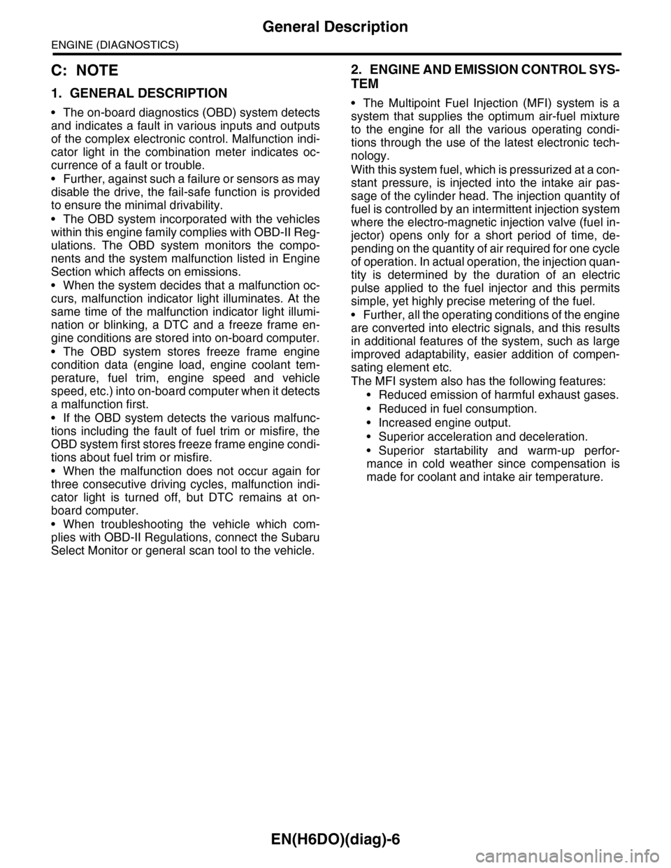
1. GENERAL DESCRIPTION
•The on-board diagnostics (OBD) system detects
and indicates a fault in various inputs and outputs
of the complex electronic control. Malfunction indi-
cator light in the combination meter indicates oc-
currence of a fault or trouble.
•Further, against such a failure or sensors as may
disable the drive, the fail-safe function is provided
to ensure the minimal drivability.
•The OBD system incorporated with the vehicles
within this engine family complies with OBD-II Reg-
ulations. The OBD system monitors the compo-
nents and the system malfunction listed in Engine
Section which affects on emissions.
•When the system decides that a malfunction oc-
curs, malfunction indicator light illuminates. At the
same time of the malfunction indicator light illumi-
nation or blinking, a DTC and a freeze frame en-
gine conditions are stored into on-board computer.
•The OBD system stores freeze frame engine
condition data (engine load, engine coolant tem-
perature, fuel trim, engine speed and vehicle
speed, etc.) into on-board computer when it detects
a malfunction first.
•If the OBD system detects the various malfunc-
tions including the fault of fuel trim or misfire, the
OBD system first stores freeze frame engine condi-
tions about fuel trim or misfire.
•When the malfunction does not occur again for
three consecutive driving cycles, malfunction indi-
cator light is turned off, but DTC remains at on-
board computer.
•When troubleshooting the vehicle which com-
plies with OBD-II Regulations, connect the Subaru
Select Monitor or general scan tool to the vehicle.
2. ENGINE AND EMISSION CONTROL SYS-
TEM
•The Multipoint Fuel Injection (MFI) system is a
system that supplies the optimum air-fuel mixture
to the engine for all the various operating condi-
tions through the use of the latest electronic tech-
nology.
With this system fuel, which is pressurized at a con-
stant pressure, is injected into the intake air pas-
sage of the cylinder head. The injection quantity of
fuel is controlled by an intermittent injection system
where the electro-magnetic injection valve (fuel in-
jector) opens only for a short period of time, de-
pending on the quantity of air required for one cycle
of operation. In actual operation, the injection quan-
tity is determined by the duration of an electric
pulse applied to the fuel injector and this permits
simple, yet highly precise metering of the fuel.
•Further, all the operating conditions of the engine
are converted into electric signals, and this results
in additional features of the system, such as large
improved adaptability, easier addition of compen-
sating element etc.
The MFI system also has the following features:
•Reduced emission of harmful exhaust gases.
•Reduced in fuel consumption.
•Increased engine output.
•Superior acceleration and deceleration.
•Superior startability and warm-up perfor-
mance in cold weather since compensation is
made for coolant and intake air temperature.
Page 1170 of 2453

EN(H6DO)(diag)-9
Electrical Component Location
ENGINE (DIAGNOSTICS)
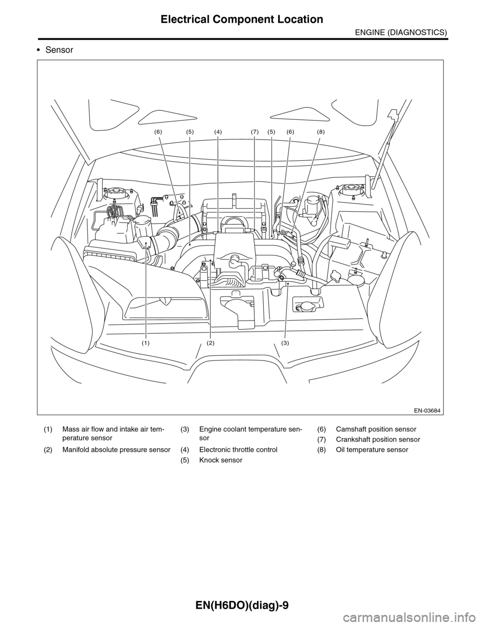
•Sensor
(1) Mass air flow and intake air tem-
perature sensor
(3) Engine coolant temperature sen-
sor
(6) Camshaft position sensor
(7) Crankshaft position sensor
(2) Manifold absolute pressure sensor (4) Electronic throttle control (8) Oil temperature sensor
(5) Knock sensor
EN-03684
(6)(6) (8)
(3)(2)
(7)
(1)
(4) (5)(5)