Page 235 of 2453

EB-16
Front Door
EXTERIOR BODY PANELS
4. Front Door
A: REMOVAL
1) Disconnect the ground cable from battery.
2) Remove the front door trim.
MOVAL, Door Trim.>
3) Remove the outer mirror assembly.
GW-13, REMOVAL, Outer Mirror Assembly.>
4) Remove the front door speaker.
REMOVAL, Front Speaker.>
5) Remove the sealing cover.
MOVAL, Front Sealing Cover.>
6) Remove the front door glass.
REMOVAL, Front Door Glass.>
7) Remove the door sash, and remove the front
door regulator and motor assemblies.
10, REMOVAL, Front Regulator and Motor Assem-
bly.>
8) Remove the front inner remote.
REMOVAL, Front Inner Remote.>
9) Remove the front door latch assembly.
SL-36, REMOVAL, Front Door Latch and Door
Lock Actuator Assembly.>
10) Remove the front outer handle.
REMOVAL, Front Outer Handle.>
11) Remove the front door weather strip.
NOTE:
If the weather strip clip is removed with excessive
force, the weather strip may be damaged. Be sure
to use clip remover to remove.
12) Remove the bolts and nuts to remove the door
checker.
13) Remove the instrument panel lower cover or
glove box lower cover.
Instrument Panel Lower Cover.> or
REMOVAL, Glove Box.>
14) Disconnect the connector of door harness from
body harness.
15) Put a wooden block on jack and place jack un-
der the front door. Support the door with a jack to
protect it from damage.
16) Remove the door-side bolts for upper and low-
er hinges to remove front door panel.
17) Remove the door hinge from vehicle.
EB-00141
EB-00154
EB-00151
EB-00013
EB-00015
Page 238 of 2453

EB-19
Rear Door
EXTERIOR BODY PANELS
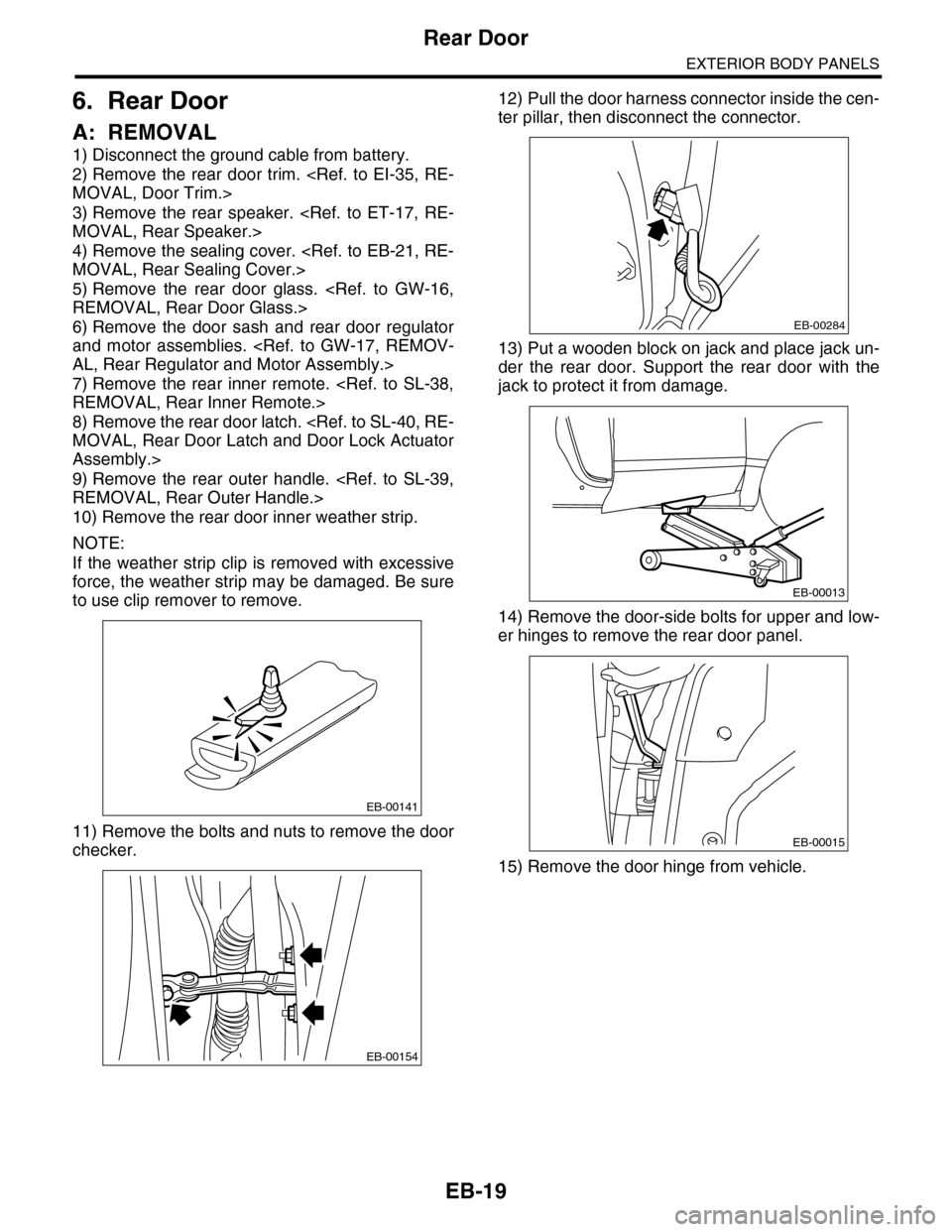
6. Rear Door
A: REMOVAL
1) Disconnect the ground cable from battery.
2) Remove the rear door trim.
MOVAL, Door Trim.>
3) Remove the rear speaker.
MOVAL, Rear Speaker.>
4) Remove the sealing cover.
MOVAL, Rear Sealing Cover.>
5) Remove the rear door glass.
REMOVAL, Rear Door Glass.>
6) Remove the door sash and rear door regulator
and motor assemblies.
AL, Rear Regulator and Motor Assembly.>
7) Remove the rear inner remote.
REMOVAL, Rear Inner Remote.>
8) Remove the rear door latch.
MOVAL, Rear Door Latch and Door Lock Actuator
Assembly.>
9) Remove the rear outer handle.
REMOVAL, Rear Outer Handle.>
10) Remove the rear door inner weather strip.
NOTE:
If the weather strip clip is removed with excessive
force, the weather strip may be damaged. Be sure
to use clip remover to remove.
11) Remove the bolts and nuts to remove the door
checker.
12) Pull the door harness connector inside the cen-
ter pillar, then disconnect the connector.
13) Put a wooden block on jack and place jack un-
der the rear door. Support the rear door with the
jack to protect it from damage.
14) Remove the door-side bolts for upper and low-
er hinges to remove the rear door panel.
15) Remove the door hinge from vehicle.
EB-00141
EB-00154
EB-00284
EB-00013
EB-00015
Page 333 of 2453
AC-7
General Description
HVAC SYSTEM (HEATER, VENTILATOR AND A/C)
(1) Heater unit case LH (9) Evaporator cover (17) Heater Core
(2) Separator (10) Power transistor (18) Heater pipe clamp
(3) Mode door RR (11) Pipe cover (19) Heater core cover
(4) Mode door FR (12) Drain hose (20) Air mix door actuator LH
(5) Air mix door LH (13) Air mix door actuator RH (21) Aspirator
(6) Air mix door RH (14) Expansion valve
(7) Heater unit case RH (15) Evaporator sensorTightening torque: N·m (kgf-m, ft-lb)
(8) Mode door actuator (16) EvaporatorT: 7.5 (0.76, 5.5)
Page 334 of 2453
AC-8
General Description
HVAC SYSTEM (HEATER, VENTILATOR AND A/C)
2. BLOWER MOTOR UNIT
Front
(1) Upper case (5) Filter coverTightening torque: N·m (kgf-m, ft-lb)
(2) Blower plate (6) Control unit (Auto A/C model)T: 7.5 (0.76, 5.5)
(3) Lower case (7) FRESH/RECIRC door actuator
(4) Blower motor (8) Filter
AC-01269
T
T
(8)
(1)
(2)
(3)
(4)
(5)(6)
(7)
Page 352 of 2453
AC-26
Blower Motor Unit Assembly
HVAC SYSTEM (HEATER, VENTILATOR AND A/C)
7. Blower Motor Unit Assembly
A: REMOVAL
1) Disconnect the ground cable from battery.
2) Remove the glove box.
AL, Glove Box.>
3) Disconnect the connectors of the A/C control
module, intake door actuator, blower motor, power
transistor and blower resistor.
4) Lift the floor mat.
5) Loosen the bolt and nut to remove blower motor
unit assembly.
B: INSTALLATION
Install in the reverse order of removal.
Tightening torque:
Refer to “COMPONENT” of “General Descrip-
tion”.
UNIT, COMPONENT, General Description.>
PONENT, General Description.>
AC-01276
Page 361 of 2453

AC-35
Heater and Cooling Unit
HVAC SYSTEM (HEATER, VENTILATOR AND A/C)
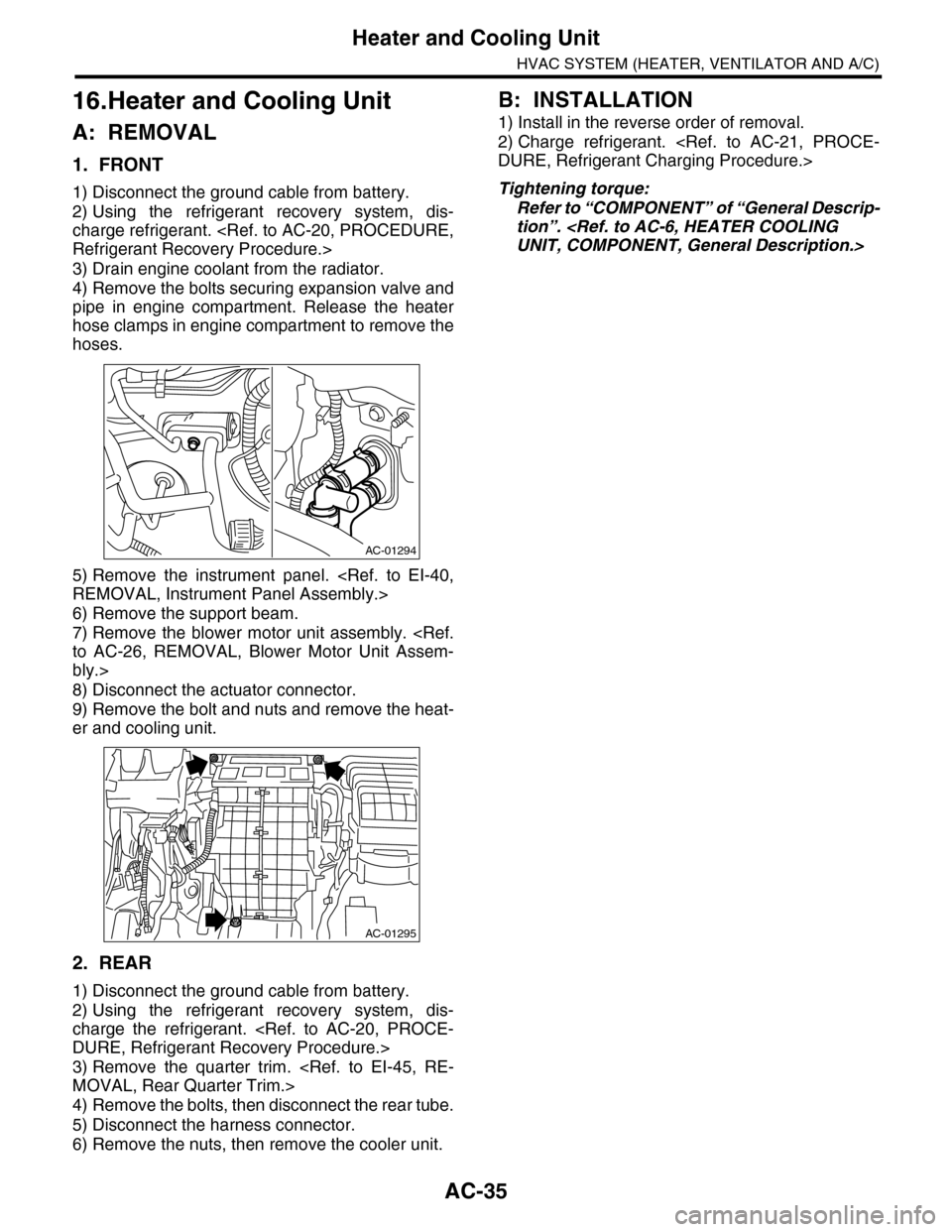
16.Heater and Cooling Unit
A: REMOVAL
1. FRONT
1) Disconnect the ground cable from battery.
2) Using the refrigerant recovery system, dis-
charge refrigerant.
Refrigerant Recovery Procedure.>
3) Drain engine coolant from the radiator.
4) Remove the bolts securing expansion valve and
pipe in engine compartment. Release the heater
hose clamps in engine compartment to remove the
hoses.
5) Remove the instrument panel.
REMOVAL, Instrument Panel Assembly.>
6) Remove the support beam.
7) Remove the blower motor unit assembly.
to AC-26, REMOVAL, Blower Motor Unit Assem-
bly.>
8) Disconnect the actuator connector.
9) Remove the bolt and nuts and remove the heat-
er and cooling unit.
2. REAR
1) Disconnect the ground cable from battery.
2) Using the refrigerant recovery system, dis-
charge the refrigerant.
DURE, Refrigerant Recovery Procedure.>
3) Remove the quarter trim.
MOVAL, Rear Quarter Trim.>
4) Remove the bolts, then disconnect the rear tube.
5) Disconnect the harness connector.
6) Remove the nuts, then remove the cooler unit.
B: INSTALLATION
1) Install in the reverse order of removal.
2) Charge refrigerant.
DURE, Refrigerant Charging Procedure.>
Tightening torque:
Refer to “COMPONENT” of “General Descrip-
tion”.
UNIT, COMPONENT, General Description.>
AC-01294
AC-01295
Page 362 of 2453

AC-36
Evaporator
HVAC SYSTEM (HEATER, VENTILATOR AND A/C)
17.Evaporator
A: REMOVAL
1. FRONT
1) Using the refrigerant recovery system, dis-
charge refrigerant.
Refrigerant Recovery Procedure.>
2) Disconnect the ground cable from battery.
3) Remove the blower motor unit assembly.
to AC-26, REMOVAL, Blower Motor Unit Assem-
bly.>
4) Disconnect the connector, remove the screw
and then remove the air-mix door actuator and
mode door actuator.
5) Remove the bolts holding the expansion valve,
and remove the expansion valve.
6) Remove the screws and pull out the evaporator.
7) Remove the pipe cover from the evaporator.
8) Remove the bolt which holds the pipe to evapo-
rator, and remove the evaporator.
CAUTION:
If the evaporator is replaced, add an appropri-
ate amount of compressor oil to the evaporator.
Oil.>
2. REAR
1) Using the refrigerant recovery system, dis-
charge the refrigerant.
DURE, Refrigerant Recovery Procedure.>
2) Disconnect the ground cable from battery.
3) Remove the rear cooler unit.
REMOVAL, Heater and Cooling Unit.>
4) Remove the pipe bracket bolts and remove the
bracket.
AC-01296
AC-01298
AC-01300
AC-01317
AC-01299
AC-01343
Page 368 of 2453
AC-42
Actuator
HVAC SYSTEM (HEATER, VENTILATOR AND A/C)
21.Actuator
A: REMOVAL
1. MODE DOOR ACTUATOR
Disconnect the connector, remove the screw, and
then remove the mode door actuator from the heat-
er and cooling unit.
2. FRESH/RECIRC DOOR ACTUATOR
Disconnect the connector, remove the screw, and
then remove the intake door actuator from the
blower motor unit.
3. AIR MIX DOOR ACTUATOR (AUTO A/C
MODEL)
Disconnect the connector, remove the screw, and
then remove the air mix door actuator from the
heater and cooling unit.
•Driver’s side
•Passenger’s side
B: INSTALLATION
Install in the reverse order of removal.
AC-01303
AC-01304
AC-01306
AC-01305