2009 SUBARU TRIBECA radiator cap
[x] Cancel search: radiator capPage 330 of 2453

AC-4
General Description
HVAC SYSTEM (HEATER, VENTILATOR AND A/C)
•Dual A/C model (Front A/C and Rear cooler)
Item Specification
Ty p e o f a i r c o n d i t i o n e rFr o nt Reh e at a ir - mi x t y pe
Rear Cooler
Cooling capacity7.2 kW
(5,331 kcal/h, 21,154 BTU/h)
RefrigerantHFC-134a (CH2FCF3)
[0.87±0.03 kg (1.92±0.07 lb)]
Compressor
Ty p eInclined plate (SWASH PLATE), fixed capacity
(10SR17), Temperature fuse
Exhaust 177 cc (10.80 cu in)/rev
Max. permissible speed 6,000 rpm
Magnet clutch
Ty p e D r y, s i n g l e - d i s c t y p e
Powe r c on su mp t i on 35 W
Ty p e o f b e l t V- b e l t 6 P K
Pulley dia. (effective dia.) 115 mm (3.7 in)
Pulley ratio 1.16
Condenser
Ty p e C o r r u g a t e d f i n ( S u b c o o l t y p e )
Core face area0.29 m2 (2.077 sq ft)
Core thickness 16 mm (0.63 in)
Radiation area7.65 m2 (61.57 sq ft)
Receiver drier Effective inner capacity 280 cc (17.1 cu in)
Expansion valveFront TypeBox time (external pressure equalizing type)Rear Type
Evaporator
Front Type Single tank
Dimensions (W × H × T)293.1 × 211 × 38 mm
(11.54 × 8.31× 1.50 in)
Rear
Ty p e S i n g l e t a n k
Dimensions (W × H × T)132.1 × 181 × 38 mm
(5.2 × 7.13× 1.50 in)
Blower fan
Front Fan type Sirocco fan
Outer diameter× width 165 ×75 mm (6.49 × 2.95 in)
Powe r c on su mp t i on 2 60 W
Rear
Fan t yp e S i r oc co fa n
Outer diameter× width 150 ×70 mm (5.91 × 2.95 in)
Powe r c on su mp t i on 1 5 0 W or l es s
Condenser fan (Sub fan)
Motor type Magnet
Powe r c on su mp t i on 1 60 W
Fan o ut e r d i am et e r 3 20 mm (1 2 . 6 i n)
Radiator fan (Main fan)
Motor type Magnet
Powe r c on su mp t i on 1 60 W
Fan o ut e r d i am et e r 3 20 mm (1 2 . 6 i n)
Idling speed (A/C ON) MPFI model 800±100 rpm
Page 1121 of 2453
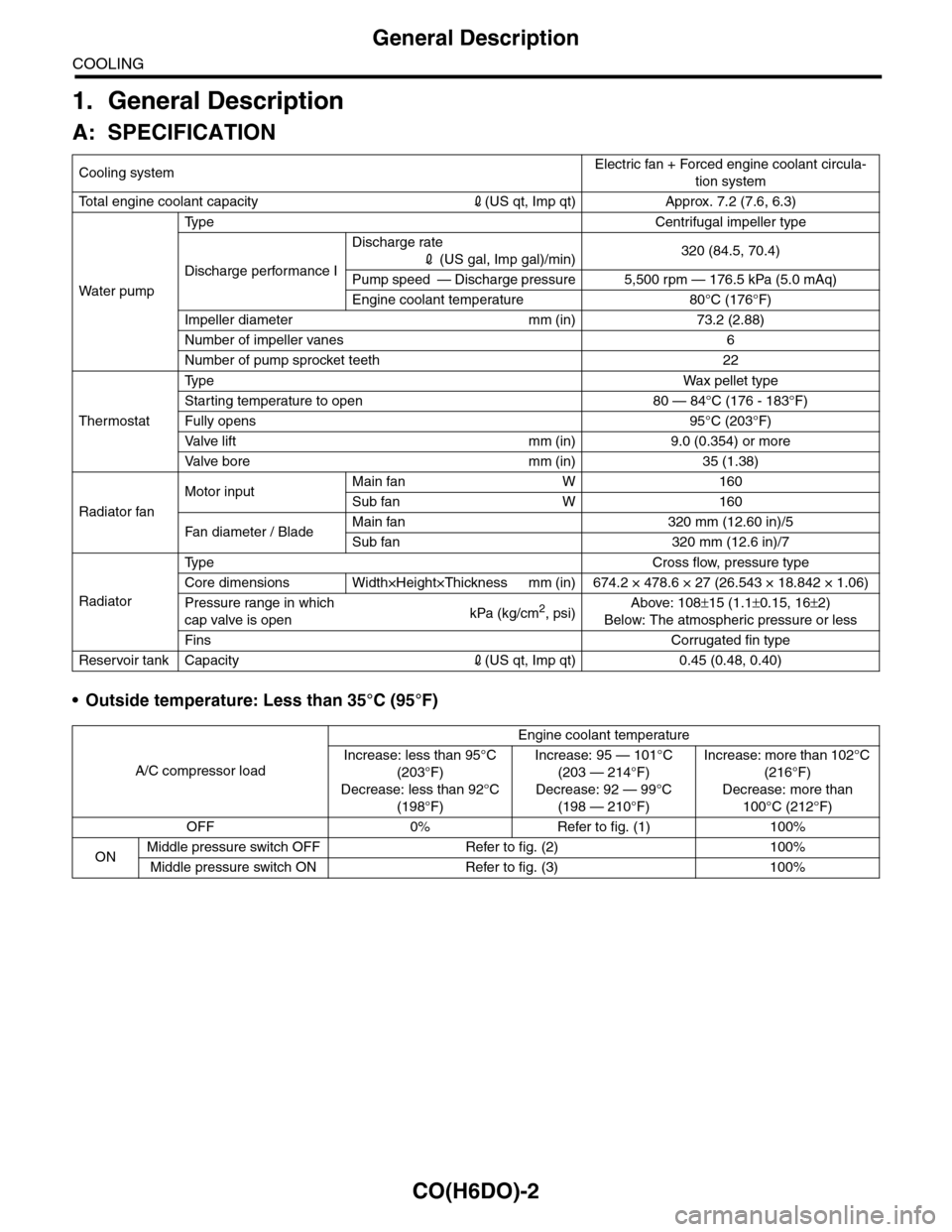
CO(H6DO)-2
General Description
COOLING
1. General Description
A: SPECIFICATION
•Outside temperature: Less than 35°C (95°F)
Cooling systemElectric fan + Forced engine coolant circula-
tion system
To t a l e n g i n e c o o l a n t c a p a c i t y2(US qt, Imp qt) Approx. 7.2 (7.6, 6.3)
Wa t er p u mp
Ty p e C e n t r i f u g a l i m p e l l e r t y p e
Discharge performance I
Discharge rate
2 (US gal, Imp gal)/min)320 (84.5, 70.4)
Pump speed — Discharge pressure 5,500 rpm — 176.5 kPa (5.0 mAq)
Engine coolant temperature 80°C (176°F)
Impeller diameter mm (in) 73.2 (2.88)
Number of impeller vanes 6
Number of pump sprocket teeth 22
Thermostat
Ty p eWa x p el l et t yp e
Starting temperature to open 80 — 84°C (176 - 183°F)
Fully opens 95°C (203°F)
Va l ve l i f t m m ( i n ) 9 . 0 ( 0 . 3 5 4 ) o r m o r e
Va l ve b o r e m m ( i n ) 3 5 ( 1 . 3 8 )
Radiator fan
Motor inputMain fan W 160
Sub fan W 160
Fan di a me t er / B la deMain fan 320 mm (12.60 in)/5
Sub fan 320 mm (12.6 in)/7
Radiator
Ty p e C r o s s f l o w , p r e s s u r e t y p e
Core dimensions Width×Height×Thickness mm (in) 674.2 × 478.6 × 27 (26.543 × 18.842 × 1.06)
Pressure range in which
cap valve is openkPa (kg/cm2, psi)Above: 108±15 (1.1±0.15, 16±2)
Below: The atmospheric pressure or less
FinsCorrugated fin type
Reservoir tank Capacity2(US qt, Imp qt) 0.45 (0.48, 0.40)
A/C compressor load
Engine coolant temperature
Increase: less than 95°C
(203°F)
Decrease: less than 92°C
(198°F)
Increase: 95 — 101°C
(203 — 214°F)
Decrease: 92 — 99°C
(198 — 210°F)
Increase: more than 102°C
(216°F)
Decrease: more than
100°C (212°F)
OFF 0% Refer to fig. (1) 100%
ONMiddle pressure switch OFF Refer to fig. (2) 100%
Middle pressure switch ON Refer to fig. (3) 100%
Page 1124 of 2453
CO(H6DO)-5
General Description
COOLING
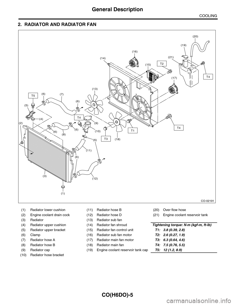
2. RADIATOR AND RADIATOR FAN
(1) Radiator lower cushion (11) Radiator hose B (20) Over flow hose
(2) Engine coolant drain cock (12) Radiator hose D (21) Engine coolant reservoir tank
(3) Radiator (13) Radiator sub fan
(4) Radiator upper cushion (14) Radiator fan shroudTightening torque: N·m (kgf-m, ft-lb)
(5) Radiator upper bracket (15) Radiator fan control unitT1: 3.8 (0.39, 2.8)
(6) Clamp (16) Radiator sub fan motorT2: 2.6 (0.27, 1.9)
(7) Radiator hose A (17) Radiator main fan motorT3: 6.3 (0.64, 4.6)
(8) Radiator hose B (18) Radiator main fanT4: 7.5 (0.76, 5.5)
(9) Radiator cap (19) Engine coolant reservoir tank capT5: 12 (1.2, 8.9)
(10) Radiator hose bracket
CO-02191
T4
T4
T4
T2
T1
T3
T5(7)
(6)
(13)
(18)
(14)
(16)
(17)
(15)
(21)
(19)
(20)
(9)
(10)
(6)
(11)
(6)
(1)
(3)
(2)
(12)
(6)
(8)
(4)
(5)
(6)(6)
Page 1125 of 2453
CO(H6DO)-6
General Description
COOLING
C: CAUTION
•Wear work clothing, including a cap, protective goggles and protective shoes during operation.
•Remove contamination including dirt and corrosion before removal, installation or disassembly.
•Keep the disassembled parts in order and protect them from dust and dirt.
•Before removal, installation or disassembly, be sure to clarify the failure. Avoid unnecessary removal, in-
stallation, disassembly and replacement.
•Be careful not to burn yourself, because each part on the vehicle is hot after running.
•Be sure to tighten fasteners including bolts and nuts to the specified torque.
•Place shop jacks or rigid racks at the specified points.
•Before disconnecting connectors of sensors or units, be sure to disconnect the ground cable from battery.
D: PREPARATION TOOL
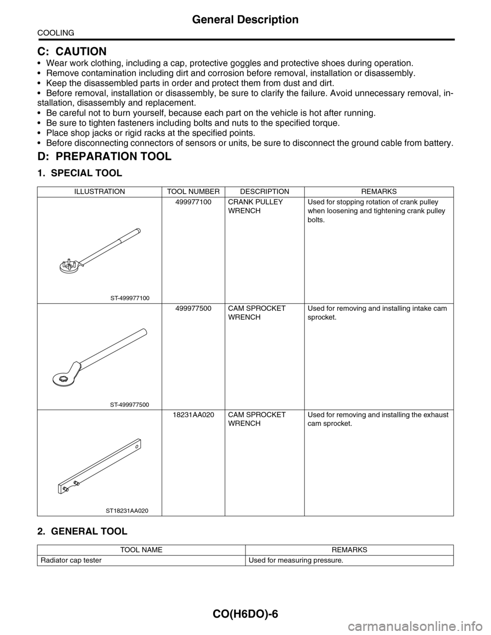
1. SPECIAL TOOL
2. GENERAL TOOL
ILLUSTRATION TOOL NUMBER DESCRIPTION REMARKS
499977100 CRANK PULLEY
WRENCH
Used for stopping rotation of crank pulley
when loosening and tightening crank pulley
bolts.
499977500 CAM SPROCKET
WRENCH
Used for removing and installing intake cam
sprocket.
18231AA020 CAM SPROCKET
WRENCH
Used for removing and installing the exhaust
cam sprocket.
TOOL NAME REMARKS
Radiator cap tester Used for measuring pressure.
ST-499977100
ST-499977500
ST18231AA020
Page 1129 of 2453
CO(H6DO)-10
Engine Coolant
COOLING
3. Engine Coolant
A: REPLACEMENT
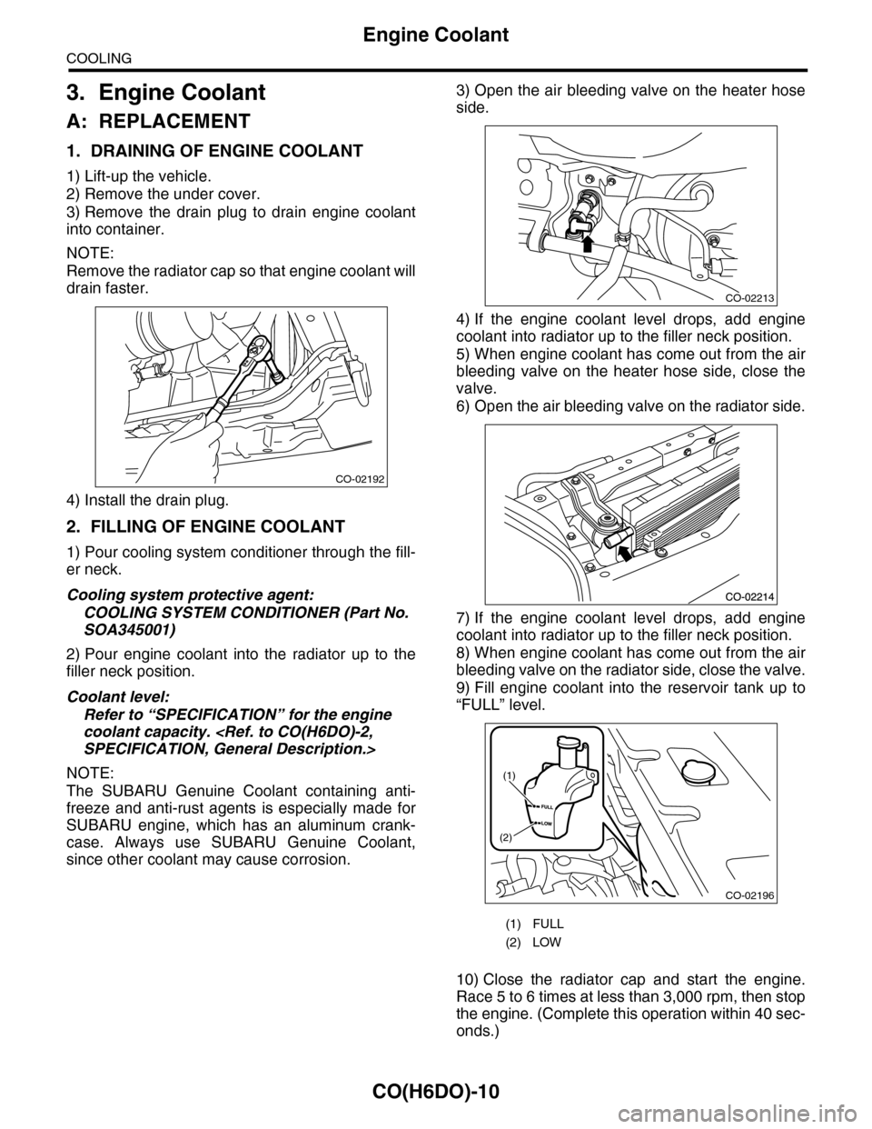
1. DRAINING OF ENGINE COOLANT
1) Lift-up the vehicle.
2) Remove the under cover.
3) Remove the drain plug to drain engine coolant
into container.
NOTE:
Remove the radiator cap so that engine coolant will
drain faster.
4) Install the drain plug.
2. FILLING OF ENGINE COOLANT
1) Pour cooling system conditioner through the fill-
er neck.
Cooling system protective agent:
COOLING SYSTEM CONDITIONER (Part No.
SOA345001)
2) Pour engine coolant into the radiator up to the
filler neck position.
Coolant level:
Refer to “SPECIFICATION” for the engine
coolant capacity.
NOTE:
The SUBARU Genuine Coolant containing anti-
freeze and anti-rust agents is especially made for
SUBARU engine, which has an aluminum crank-
case. Always use SUBARU Genuine Coolant,
since other coolant may cause corrosion.
3) Open the air bleeding valve on the heater hose
side.
4) If the engine coolant level drops, add engine
coolant into radiator up to the filler neck position.
5) When engine coolant has come out from the air
bleeding valve on the heater hose side, close the
valve.
6) Open the air bleeding valve on the radiator side.
7) If the engine coolant level drops, add engine
coolant into radiator up to the filler neck position.
8) When engine coolant has come out from the air
bleeding valve on the radiator side, close the valve.
9) Fill engine coolant into the reservoir tank up to
“FULL” level.
10) Close the radiator cap and start the engine.
Race 5 to 6 times at less than 3,000 rpm, then stop
the engine. (Complete this operation within 40 sec-
onds.)
CO-02192
(1) FULL
(2) LOW
CO-02213
CO-02196
(1)
(2)
Page 1130 of 2453
CO(H6DO)-11
Engine Coolant
COOLING
11) Wait for one minute after the engine stops,
open the radiator cap. If the engine coolant level
drops, add engine coolant into radiator up to the fill-
er neck position.
12) Perform the procedures 10) and 11) again.
13) Attach the radiator cap and reservoir tank cap
properly.
14) Start the engine and operate the heater at max-
imum hot position and the blower speed setting to
“LO.”
15) Run the engine at 2,000 rpm or less until radia-
tor fan starts and stops.
NOTE:
•Be careful with the engine coolant temperature
gauge to prevent overheating.
•If the radiator hose becomes harden with the
pressure of engine coolant, air bleeding operation
seems to be almost completed.
16) Stop the engine and wait until the engine cool-
ant temperature lowers to 30°C (86°F).
17) Open the radiator cap. If the engine coolant lev-
el drops, add engine coolant into radiator up to the
filler neck position and reservoir tank to the “FULL”
level.
18) Attach the radiator cap and reservoir tank cap
properly.
19) Set the heater setting to maximum hot position
and the blower speed setting to “LO” and start the
engine. Perform racing at less than 3,000 rpm. If
the flowing sound is heard at this time, perform the
procedures from 15) again.
B: INSPECTION
1. RELATIONSHIP OF SUBARU COOLANT
CONCENTRATION AND FREEZING TEM-
PERATURE
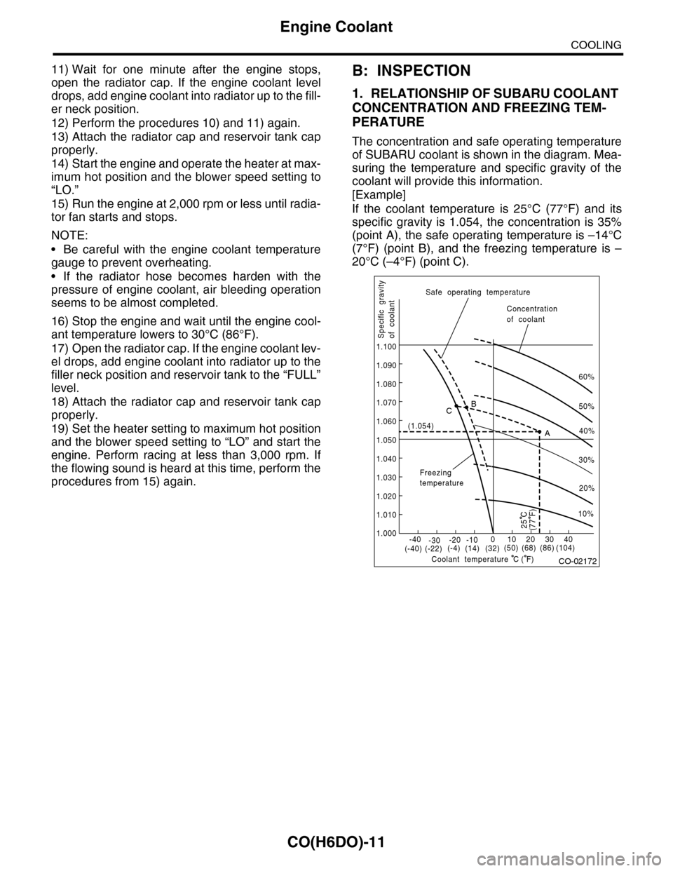
The concentration and safe operating temperature
of SUBARU coolant is shown in the diagram. Mea-
suring the temperature and specific gravity of the
coolant will provide this information.
[Example]
If the coolant temperature is 25°C (77°F) and its
specific gravity is 1.054, the concentration is 35%
(point A), the safe operating temperature is –14°C
(7°F) (point B), and the freezing temperature is –
20°C (–4°F) (point C).
CO-02172
60%
(1.054)
1.000
1.010
1.020
1.030
1.040
1.050
1.060
1.070
1.080
1.090
1.100
Safe operating temperature
Freezingtemperature
Concentrationof coolant
Specific gravityof coolant
Coolant temperature
B
A
C
-40(-40) (-22)(-4)(14)(32)(50) (68) (86)
( F)
(104)-30-20 -10010203040
(77 F)
50%
40%
30%
20%
25 C
10%
C
Page 1138 of 2453
CO(H6DO)-19
Radiator
COOLING
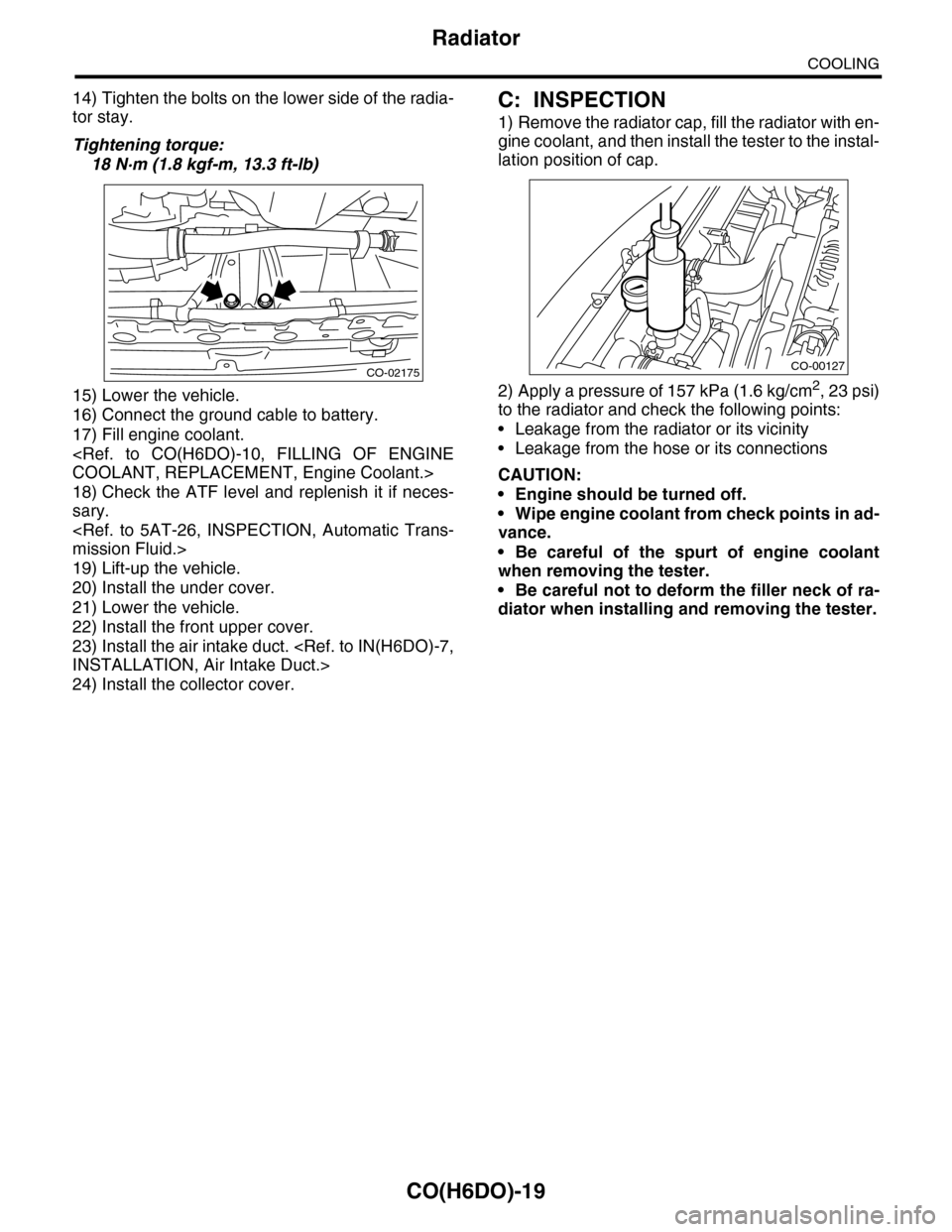
14) Tighten the bolts on the lower side of the radia-
tor stay.
Tightening torque:
18 N·m (1.8 kgf-m, 13.3 ft-lb)
15) Lower the vehicle.
16) Connect the ground cable to battery.
17) Fill engine coolant.
18) Check the ATF level and replenish it if neces-
sary.
19) Lift-up the vehicle.
20) Install the under cover.
21) Lower the vehicle.
22) Install the front upper cover.
23) Install the air intake duct.
24) Install the collector cover.
C: INSPECTION
1) Remove the radiator cap, fill the radiator with en-
gine coolant, and then install the tester to the instal-
lation position of cap.
2) Apply a pressure of 157 kPa (1.6 kg/cm2, 23 psi)
to the radiator and check the following points:
•Leakage from the radiator or its vicinity
•Leakage from the hose or its connections
CAUTION:
•Engine should be turned off.
•Wipe engine coolant from check points in ad-
vance.
•Be careful of the spurt of engine coolant
when removing the tester.
•Be careful not to deform the filler neck of ra-
diator when installing and removing the tester.
CO-02175CO-00127
Page 1139 of 2453
CO(H6DO)-20
Radiator Cap
COOLING
7. Radiator Cap
A: INSPECTION
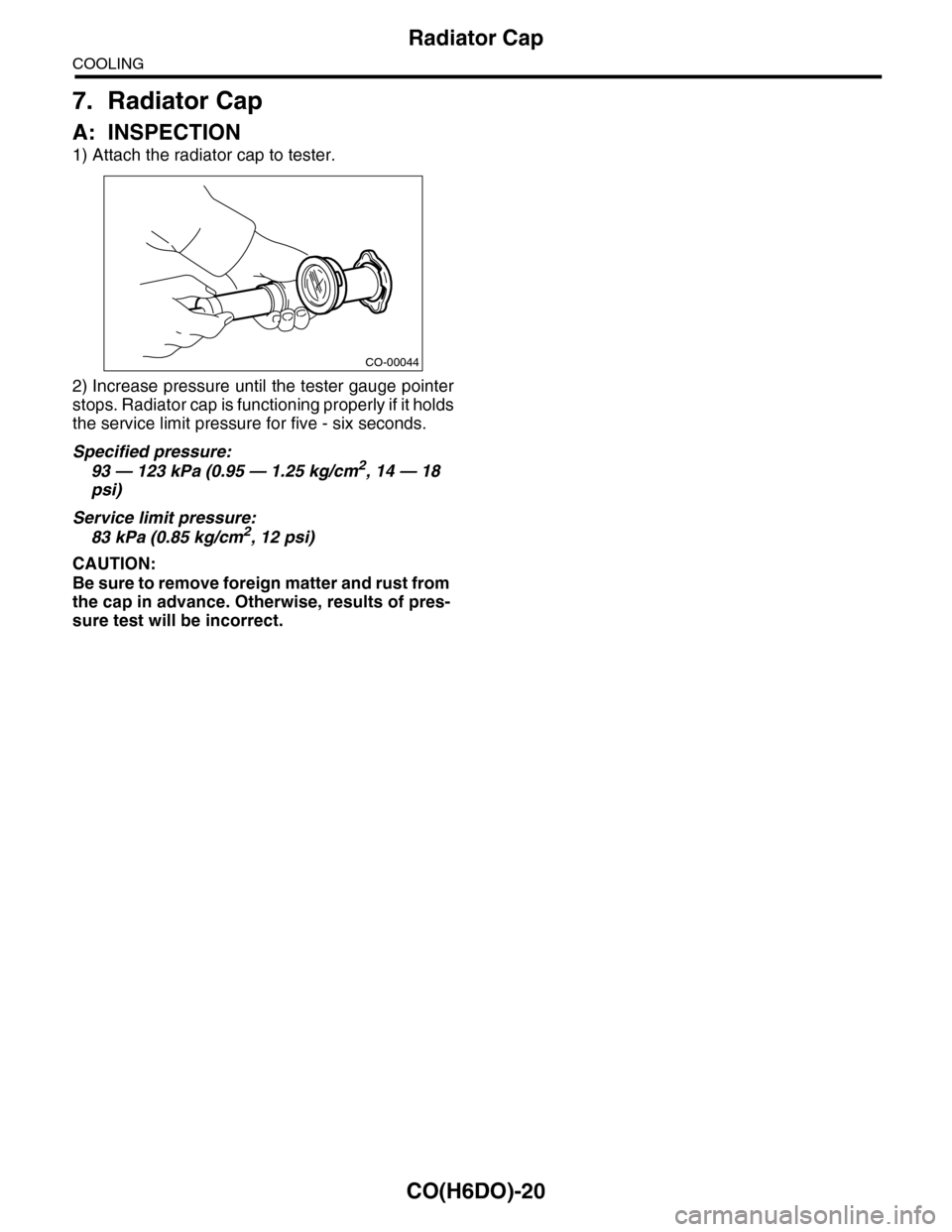
1) Attach the radiator cap to tester.
2) Increase pressure until the tester gauge pointer
stops. Radiator cap is functioning properly if it holds
the service limit pressure for five - six seconds.
Specified pressure:
93 — 123 kPa (0.95 — 1.25 kg/cm2, 14 — 18
psi)
Service limit pressure:
83 kPa (0.85 kg/cm2, 12 psi)
CAUTION:
Be sure to remove foreign matter and rust from
the cap in advance. Otherwise, results of pres-
sure test will be incorrect.
CO-00044