Page 1573 of 2453
FU(H6DO)-12
Intake Manifold
FUEL INJECTION (FUEL SYSTEMS)
3. Intake Manifold
A: REMOVAL
1) Remove the collector cover.
2) Release the fuel pressure.
37, RELEASING OF FUEL PRESSURE, PROCE-
DURE, Fuel.>
3) Disconnect the ground cable from battery.
4) Open the fuel filler flap lid, and remove the fuel
filler cap.
5) Remove the air cleaner case and air intake
chamber.
Cleaner Case.>
Air Intake Chamber.>
6) Remove the generator.
REMOVAL, Generator.>
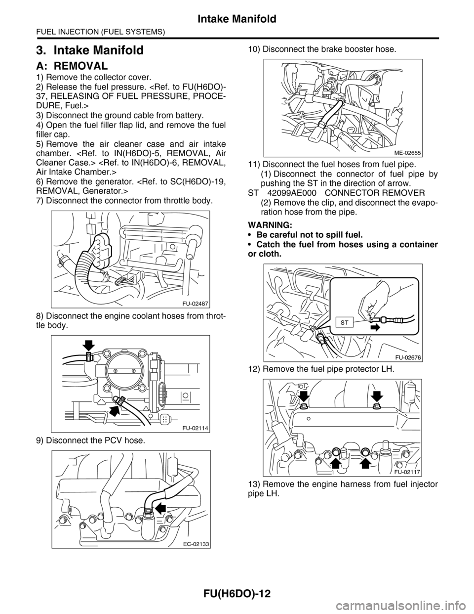
7) Disconnect the connector from throttle body.
8) Disconnect the engine coolant hoses from throt-
tle body.
9) Disconnect the PCV hose.
10) Disconnect the brake booster hose.
11) Disconnect the fuel hoses from fuel pipe.
(1) Disconnect the connector of fuel pipe by
pushing the ST in the direction of arrow.
ST 42099AE000 CONNECTOR REMOVER
(2) Remove the clip, and disconnect the evapo-
ration hose from the pipe.
WARNING:
•Be careful not to spill fuel.
•Catch the fuel from hoses using a container
or cloth.
12) Remove the fuel pipe protector LH.
13) Remove the engine harness from fuel injector
pipe LH.
FU-02487
FU-02114
EC-02133
ME-02655
FU-02117
Page 1585 of 2453
FU(H6DO)-24
Fuel Injector
FUEL INJECTION (FUEL SYSTEMS)
11.Fuel Injector
A: REMOVAL
1. RH SIDE
1) Remove the collector cover.
2) Release the fuel pressure.
37, RELEASING OF FUEL PRESSURE, PROCE-
DURE, Fuel.>
3) Disconnect the ground cable from battery.
4) Open the fuel filler flap lid, and remove the fuel
filler cap.
5) Remove the air cleaner case.
IN(H6DO)-5, REMOVAL, Air Cleaner Case.>
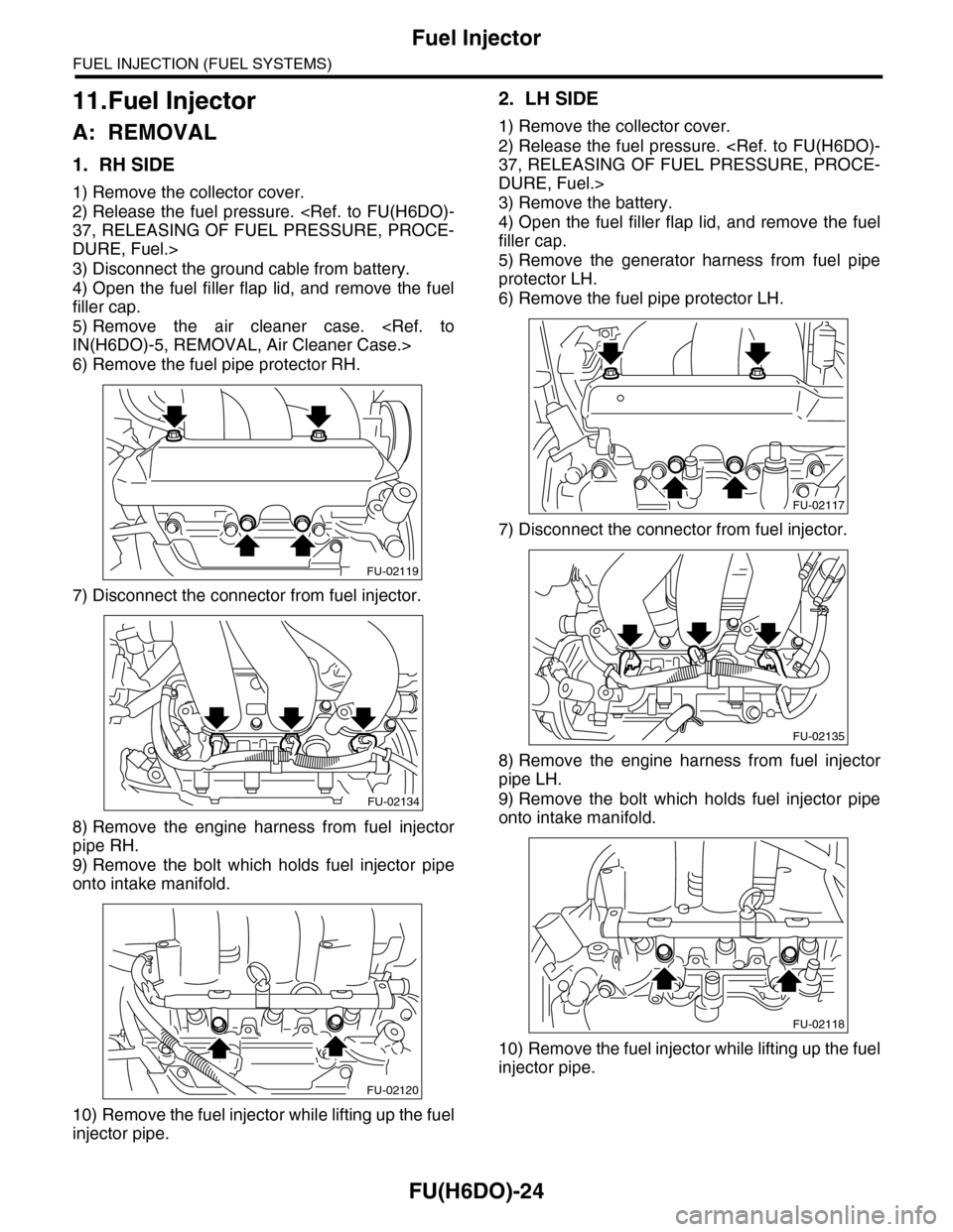
6) Remove the fuel pipe protector RH.
7) Disconnect the connector from fuel injector.
8) Remove the engine harness from fuel injector
pipe RH.
9) Remove the bolt which holds fuel injector pipe
onto intake manifold.
10) Remove the fuel injector while lifting up the fuel
injector pipe.
2. LH SIDE
1) Remove the collector cover.
2) Release the fuel pressure.
37, RELEASING OF FUEL PRESSURE, PROCE-
DURE, Fuel.>
3) Remove the battery.
4) Open the fuel filler flap lid, and remove the fuel
filler cap.
5) Remove the generator harness from fuel pipe
protector LH.
6) Remove the fuel pipe protector LH.
7) Disconnect the connector from fuel injector.
8) Remove the engine harness from fuel injector
pipe LH.
9) Remove the bolt which holds fuel injector pipe
onto intake manifold.
10) Remove the fuel injector while lifting up the fuel
injector pipe.
FU-02119
FU-02134
FU-02120
FU-02117
FU-02135
FU-02118
Page 1598 of 2453
FU(H6DO)-37
Fuel
FUEL INJECTION (FUEL SYSTEMS)
21.Fuel
A: PROCEDURE
1. RELEASING OF FUEL PRESSURE
WARNING:
•Place “NO FIRE” signs near the working area.
•Be careful not to spill fuel on the floor.
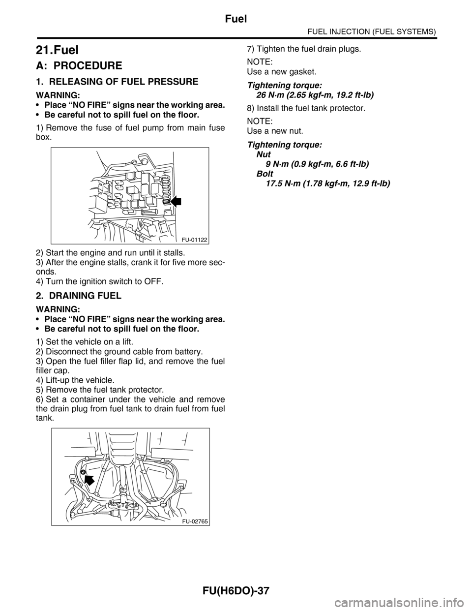
1) Remove the fuse of fuel pump from main fuse
box.
2) Start the engine and run until it stalls.
3) After the engine stalls, crank it for five more sec-
onds.
4) Turn the ignition switch to OFF.
2. DRAINING FUEL
WARNING:
•Place “NO FIRE” signs near the working area.
•Be careful not to spill fuel on the floor.
1) Set the vehicle on a lift.
2) Disconnect the ground cable from battery.
3) Open the fuel filler flap lid, and remove the fuel
filler cap.
4) Lift-up the vehicle.
5) Remove the fuel tank protector.
6) Set a container under the vehicle and remove
the drain plug from fuel tank to drain fuel from fuel
tank.
7) Tighten the fuel drain plugs.
NOTE:
Use a new gasket.
Tightening torque:
26 N·m (2.65 kgf-m, 19.2 ft-lb)
8) Install the fuel tank protector.
NOTE:
Use a new nut.
Tightening torque:
Nut
9 N·m (0.9 kgf-m, 6.6 ft-lb)
Bolt
17.5 N·m (1.78 kgf-m, 12.9 ft-lb)
FU-01122
FU-02765
Page 1599 of 2453
FU(H6DO)-38
Fuel Tank
FUEL INJECTION (FUEL SYSTEMS)
22.Fuel Tank
A: REMOVAL
WARNING:
•Place “NO FIRE” signs near the working area.
•Be careful not to spill fuel on the floor.
1) Set the vehicle on a lift.
2) Release the fuel pressure.
37, RELEASING OF FUEL PRESSURE, PROCE-
DURE, Fuel.>
3) Disconnect the ground cable from battery.
4) Drain fuel from fuel tank.
CEDURE, Fuel.>
5) Remove the second seat.
MOVAL, Second-row Seats.>
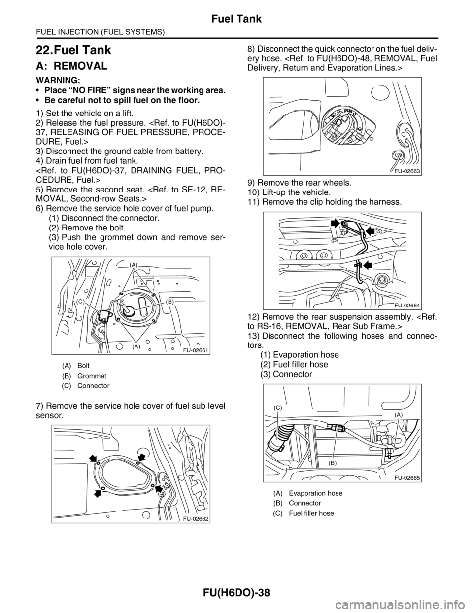
6) Remove the service hole cover of fuel pump.
(1) Disconnect the connector.
(2) Remove the bolt.
(3) Push the grommet down and remove ser-
vice hole cover.
7) Remove the service hole cover of fuel sub level
sensor.
8) Disconnect the quick connector on the fuel deliv-
ery hose.
Delivery, Return and Evaporation Lines.>
9) Remove the rear wheels.
10) Lift-up the vehicle.
11) Remove the clip holding the harness.
12) Remove the rear suspension assembly.
to RS-16, REMOVAL, Rear Sub Frame.>
13) Disconnect the following hoses and connec-
tors.
(1) Evaporation hose
(2) Fuel filler hose
(3) Connector
(A) Bolt
(B) Grommet
(C) Connector
FU-02661(A)
(A)
(B)(C)
FU-02662
(A) Evaporation hose
(B) Connector
(C) Fuel filler hose
FU-02663
FU-02664
FU-02665
(A)
(B)
(C)
Page 1604 of 2453
FU(H6DO)-43
Fuel Pump
FUEL INJECTION (FUEL SYSTEMS)
24.Fuel Pump
A: REMOVAL
WARNING:
•Place “NO FIRE” signs near the working area.
•Be careful not to spill fuel on the floor.
NOTE:
Fuel pump assembly consists of fuel pump and fuel
level sensor.
1) Release the fuel pressure.
37, RELEASING OF FUEL PRESSURE, PROCE-
DURE, Fuel.>
2) Drain fuel.
FUEL, PROCEDURE, Fuel.>
3) Remove the second seat.
MOVAL, Second-row Seats.>
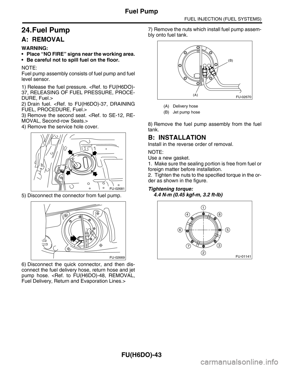
4) Remove the service hole cover.
5) Disconnect the connector from fuel pump.
6) Disconnect the quick connector, and then dis-
connect the fuel delivery hose, return hose and jet
pump hose.
Fuel Delivery, Return and Evaporation Lines.>
7) Remove the nuts which install fuel pump assem-
bly onto fuel tank.
8) Remove the fuel pump assembly from the fuel
tank.
B: INSTALLATION
Install in the reverse order of removal.
NOTE:
Use a new gasket.
1. Make sure the sealing portion is free from fuel or
foreign matter before installation.
2. Tighten the nuts to the specified torque in the or-
der as shown in the figure.
Tightening torque:
4.4 N·m (0.45 kgf-m, 3.2 ft-lb)
FU-02681
FU-02669
(A) Delivery hose
(B) Jet pump hose
FU-02670(A)
(B)
FU-01141
1
2
3
4
56
7
8
Page 1609 of 2453
FU(H6DO)-48
Fuel Delivery, Return and Evaporation Lines
FUEL INJECTION (FUEL SYSTEMS)
28.Fuel Delivery, Return and Evaporation Lines
A: REMOVAL
1) Set the vehicle on a lift.
2) Release the fuel pressure.
Fuel.>
3) Open the fuel filler flap lid, and remove the fuel filler cap.
4) Remove the floor mat.
5) Disconnect the fuel delivery pipe and hose and the evaporation pipe and hose.
6) In the engine compartment, disconnect the fuel
delivery hoses and evaporation hose.
(1) Disconnect the quick connector of the fuel
delivery line by pushing the ST in the direction
of the arrow.
ST 42099AE000 CONNECTOR REMOVER
(2) Remove the clip, and disconnect the evapo-
ration hose from the pipe.
WARNING:
•Be careful not to spill fuel.
•Catch the fuel from hoses using a container
or cloth.
7) Lift-up the vehicle.
8) Remove the fuel tank.
REMOVAL, Fuel Tank.>
FU-02675
Page 1887 of 2453
ME(H6DO)-21
Compression
MECHANICAL
2. Compression
A: INSPECTION
CAUTION:
After warming-up, engine becomes very hot. Be
careful not to burn yourself during measure-
ment.
1) After warming-up the engine, turn the ignition
switch to OFF.
2) Make sure that the battery is fully charged.
3) Release the fuel pressure.
PRESSURE, PROCEDURE, Fuel.>
4) Remove all the spark plugs.
4, REMOVAL, Spark Plug.>
5) Check the starter motor for satisfactory perfor-
mance and operation.
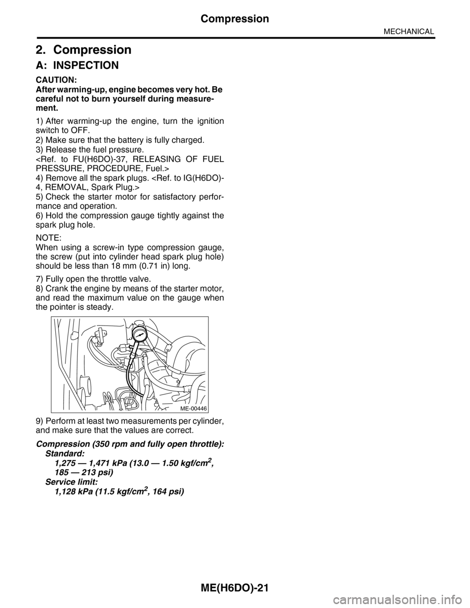
6) Hold the compression gauge tightly against the
spark plug hole.
NOTE:
When using a screw-in type compression gauge,
the screw (put into cylinder head spark plug hole)
should be less than 18 mm (0.71 in) long.
7) Fully open the throttle valve.
8) Crank the engine by means of the starter motor,
and read the maximum value on the gauge when
the pointer is steady.
9) Perform at least two measurements per cylinder,
and make sure that the values are correct.
Compression (350 rpm and fully open throttle):
Standard:
1,275 — 1,471 kPa (13.0 — 1.50 kgf/cm2,
185 — 213 psi)
Service limit:
1,128 kPa (11.5 kgf/cm2, 164 psi)
ME-00446
Page 1892 of 2453
ME(H6DO)-26
Fuel Pressure
MECHANICAL
7. Fuel Pressure
A: INSPECTION
WARNING:
Before removing the fuel pressure gauge, re-
lease the fuel pressure.
1) Release the fuel pressure.
PRESSURE, PROCEDURE, Fuel.>
2) Disconnect the fuel delivery hose and connect
fuel pressure gauge.
(1) Disconnect the fuel delivery hose using the
ST1.
ST1 42099AE000 CONNECTOR REMOVER
(2) Connect the fuel pressure meter using the
ST2 and ST3.
NOTE:
ST2 is a genuine Subaru part.
ST2 42075AG690 FUEL HOSE
ST3 18471AA000 FUEL PIPE ADAPTER
3) Install the fuse of fuel pump to main fuse box.
4) Start the engine.
5) Measure the fuel pressure after warming up the
engine.
Fuel pressure:
Standard: 338 — 348 kPa (3.4 — 3.5 kgf/cm2,
49 — 50.5 psi)
NOTE:
The fuel pressure gauge registers 10 to 20 kPa (0.1
to 0.2 kgf/cm2, 1 to 3 psi) higher than standard val-
ues during high-altitude operations.
(A) ST 2
(B) ST 3
ME-02666
(A)
(B)
FU-01122