2009 SUBARU TRIBECA engine oil capacity
[x] Cancel search: engine oil capacityPage 882 of 2453

PS-2
General Description
POWER ASSISTED SYSTEM (POWER STEERING)
1. General Description
A: SPECIFICATION
Whole system
Minimum turning radius m (ft) 5.7 (18.7)
Steering angleInner wheel 37.0°±1.5°
Outer wheel 32.0°±1.5
Steering wheel diameter mm (in) 375 (14.76)
Lock to lock turn 3.44
Gearbox
Ty p e R a c k a n d P i n i o n , I n t e g r a l
Backlash 0 (Automatic adjusting)
Va l ve ( Po w e r s t e e r i n g s y s t e m ) R o t a r y va l ve
Pump
(Power steering
system)
Ty p e Va n e p u m p
Oil tank Installed on body
Specific outputcm3 (cu in)/rev.9.6 (0.586)
Relief pressurekPa (kg/cm2, psi)8,800 — 9,400 (90 — 96, 1,276 — 1,363)
Hydraulic fluid control Engine RPM sensitive
Hydraulic fluid2(US qt, Imp qt)1,000 rpm: 7.0 (7.4, 6.2)
3,000 rpm: 6.0 (6.3, 5.3)
RPM Range rpm 500 — 8,600
Direction of rotation Clockwise
Hydraulic oil
(Power steering
system)
Description ATF DEXRON III or equivalent
Capacity
2(US qt, Imp qt)
Oil tank 0.2 (0.2, 0.2)
Whole system 0.9 (1.0, 0.8)
Steering wheel Free play mm (in) 17 (0.67)
Steering shaftClearance between the steering wheel and
column covermm (in) 3.0 (0.12)
Steering gear-
box
(Power steering
system)
Sliding resistance N (kgf, lb)
400 (41, 90) or less
Difference between right and left sliding resistance:
Less than 20%
Rack shaft play in
the radial direction
Right–turn steering mm (in) 0.19 (0.0075) or less
Left–turn steering mm (in)Horizontal movement: 0.6 (0.024) or less
Ve r t i c a l m o v e m e n t : 0 . 4 ( 0 . 0 1 6 ) o r l e s s
Input shaft playIn radial direction mm (in) 0.18 (0.0071) or less
In axial direction mm (in) 0.27 (0.0106) or less
Rotation resistance N (kgf, lb)
Maximum allowable value: 10.5 (1.07, 2.36) or less
Difference between right and left sliding resistance:
Less than 20%
Oil Pump
(Power steering
system)
Pulley shaftRadial play mm (in) 0.2 (0.008) or less
Axial play mm (in) 0.6 (0.024) or less
PulleyDitch deflection mm (in) 1.0 (0.039) or less
Rotation resistance N (kgf, lb) 9.22 (0.94, 2.07) or less
Regular pressure (Unloaded)kPa (kg/cm2, psi)981 (10, 142) or less
Steering wheel
effort (Power
steering sys-
tem)
At standstill with engine idling on paved road N (kgf, lb) 29.4 (3.0, 6.6) or less
At standstill with engine stalled on paved
roadN (kgf, lb) 294.2 (30, 66.2) or less
Page 1851 of 2453
LU(H6DO)-2
General Description
LUBRICATION
1. General Description
A: SPECIFICATION
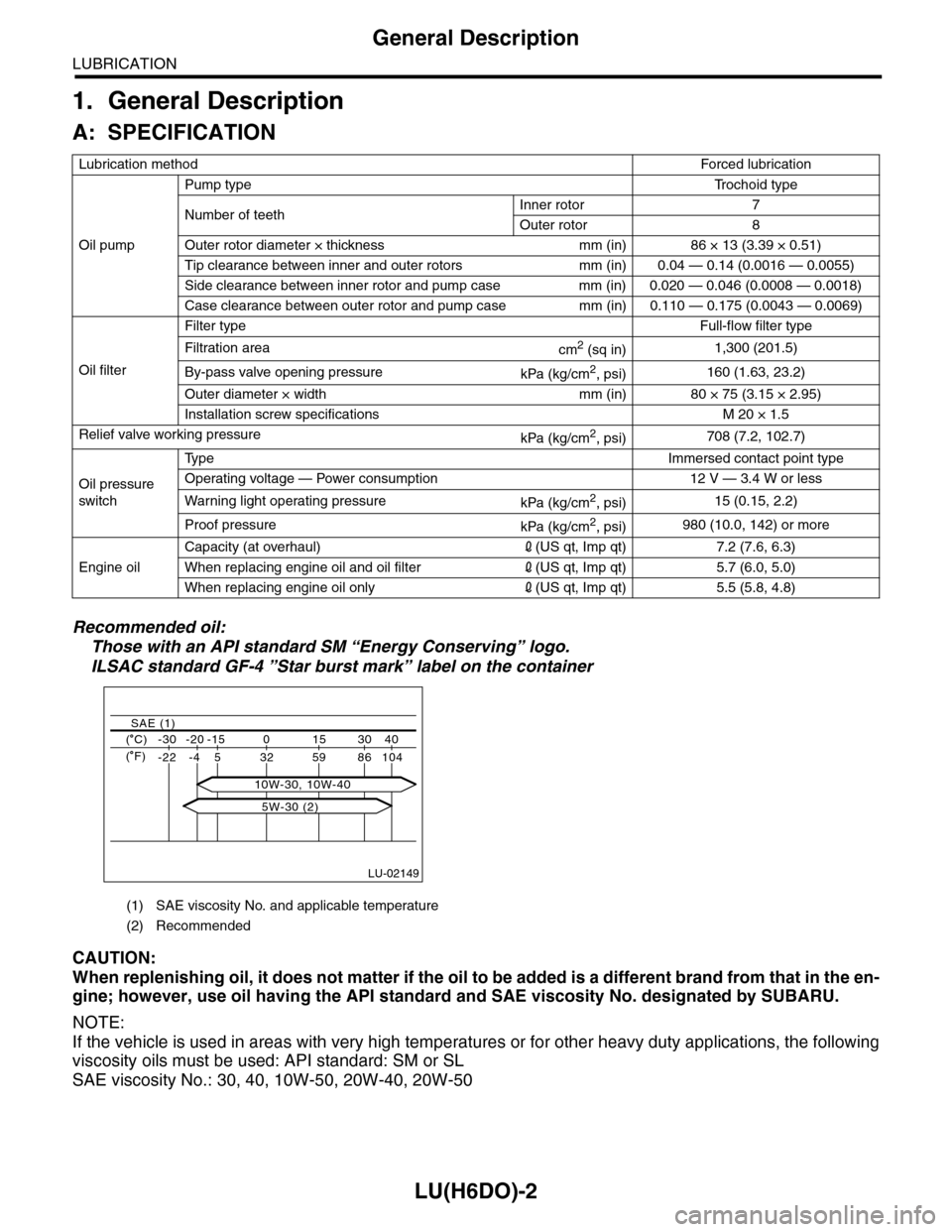
Recommended oil:
Those with an API standard SM “Energy Conserving” logo.
ILSAC standard GF-4 ”Star burst mark” label on the container
CAUTION:
When replenishing oil, it does not matter if the oil to be added is a different brand from that in the en-
gine; however, use oil having the API standard and SAE viscosity No. designated by SUBARU.
NOTE:
If the vehicle is used in areas with very high temperatures or for other heavy duty applications, the following
viscosity oils must be used: API standard: SM or SL
SAE viscosity No.: 30, 40, 10W-50, 20W-40, 20W-50
Lubrication methodForced lubr ication
Oil pump
Pump typeTr o c h o i d t y p e
Number of teethInner rotor 7
Outer rotor 8
Outer rotor diameter × thickness mm (in) 86 × 13 (3.39 × 0.51)
Tip clearance between inner and outer rotors mm (in) 0.04 — 0.14 (0.0016 — 0.0055)
Side clearance between inner rotor and pump case mm (in) 0.020 — 0.046 (0.0008 — 0.0018)
Case clearance between outer rotor and pump case mm (in) 0.110 — 0.175 (0.0043 — 0.0069)
Oil filter
Filter typeFull-flow filter type
Filtration areacm2 (sq in)1,300 (201.5)
By-pass valve opening pressurekPa (kg/cm2, psi)160 (1.63, 23.2)
Outer diameter × width mm (in) 80 × 75 (3.15 × 2.95)
Installation screw specifications M 20 × 1.5
Relief valve working pressurekPa (kg/cm2, psi)708 (7.2, 102.7)
Oil pressure
switch
Ty p eImmersed contact point type
Operating voltage — Power consumption 12 V — 3.4 W or less
Wa r ni n g l ig h t o p era t i ng pr e ss ur ekPa (kg/cm2, psi)15 (0.15, 2.2)
Proof pressurekPa (kg/cm2, psi)980 (10.0, 142) or more
Engine oil
Capacity (at overhaul)2(US qt, Imp qt) 7.2 (7.6, 6.3)
When replacing engine oil and oil filter2(US qt, Imp qt) 5.7 (6.0, 5.0)
When replacing engine oil only2(US qt, Imp qt) 5.5 (5.8, 4.8)
(1) SAE viscosity No. and applicable temperature
(2) Recommended
LU-02149
( C) -30 -20 -15 0 15 30 40
-22 -4 5 32 59 86 104
SAE (1)
( F)
5W-30 (2)
10W-30, 10W-40
Page 1856 of 2453
LU(H6DO)-7
Engine Oil
LUBRICATION
3. Engine Oil
A: INSPECTION
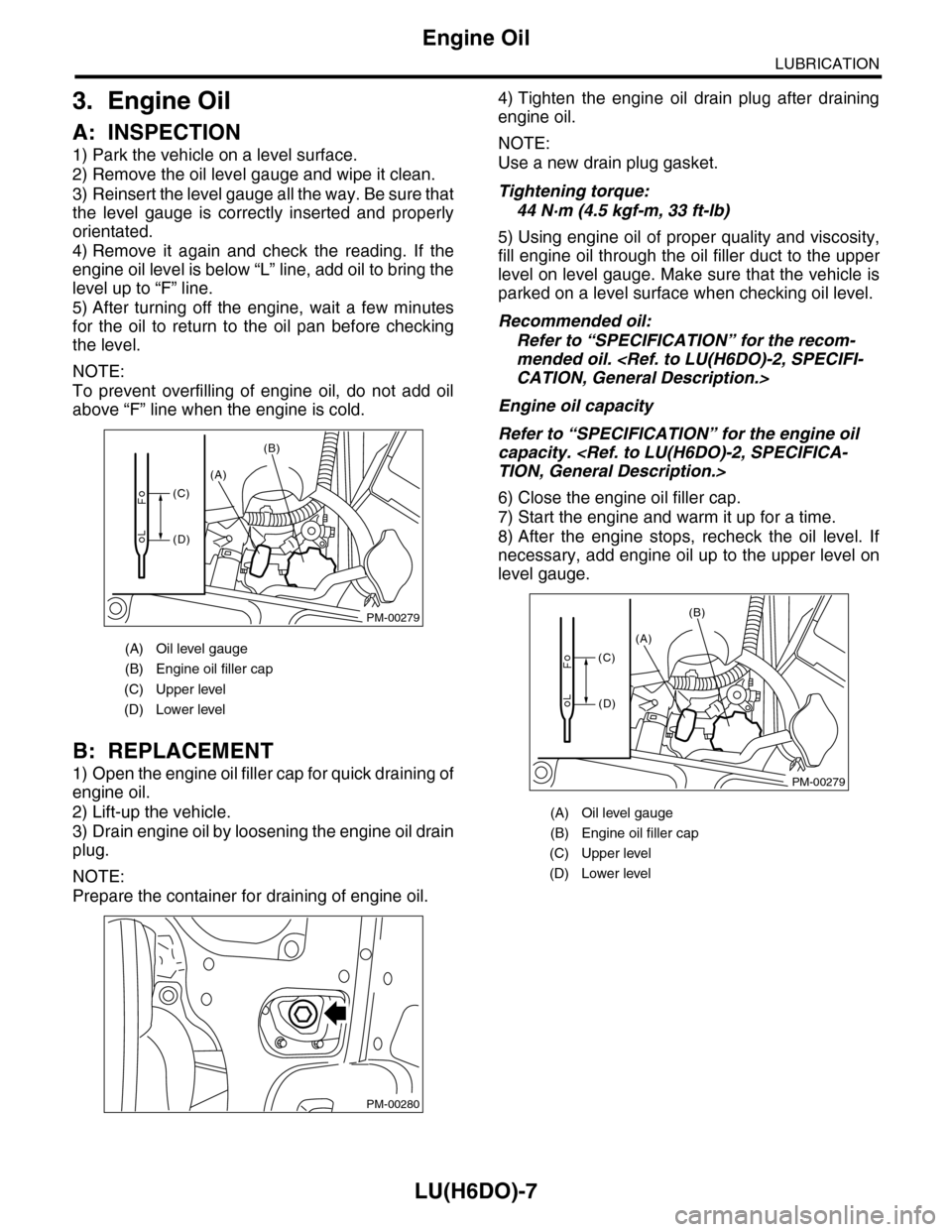
1) Park the vehicle on a level surface.
2) Remove the oil level gauge and wipe it clean.
3) Reinsert the level gauge all the way. Be sure that
the level gauge is correctly inserted and properly
orientated.
4) Remove it again and check the reading. If the
engine oil level is below “L” line, add oil to bring the
level up to “F” line.
5) After turning off the engine, wait a few minutes
for the oil to return to the oil pan before checking
the level.
NOTE:
To prevent overfilling of engine oil, do not add oil
above “F” line when the engine is cold.
B: REPLACEMENT
1) Open the engine oil filler cap for quick draining of
engine oil.
2) Lift-up the vehicle.
3) Drain engine oil by loosening the engine oil drain
plug.
NOTE:
Prepare the container for draining of engine oil.
4) Tighten the engine oil drain plug after draining
engine oil.
NOTE:
Use a new drain plug gasket.
Tightening torque:
44 N·m (4.5 kgf-m, 33 ft-lb)
5) Using engine oil of proper quality and viscosity,
fill engine oil through the oil filler duct to the upper
level on level gauge. Make sure that the vehicle is
parked on a level surface when checking oil level.
Recommended oil:
Refer to “SPECIFICATION” for the recom-
mended oil.
Engine oil capacity
Refer to “SPECIFICATION” for the engine oil
capacity.
6) Close the engine oil filler cap.
7) Start the engine and warm it up for a time.
8) After the engine stops, recheck the oil level. If
necessary, add engine oil up to the upper level on
level gauge.
(A) Oil level gauge
(B) Engine oil filler cap
(C) Upper level
(D) Lower level
PM-00279
(A)
(B)
(C)
(D)
PM-00280
(A) Oil level gauge
(B) Engine oil filler cap
(C) Upper level
(D) Lower level
PM-00279
(A)
(B)
(C)
(D)
Page 1989 of 2453
PM-6
Engine Oil
PERIODIC MAINTENANCE SERVICES
3. Engine Oil
A: REPLACEMENT
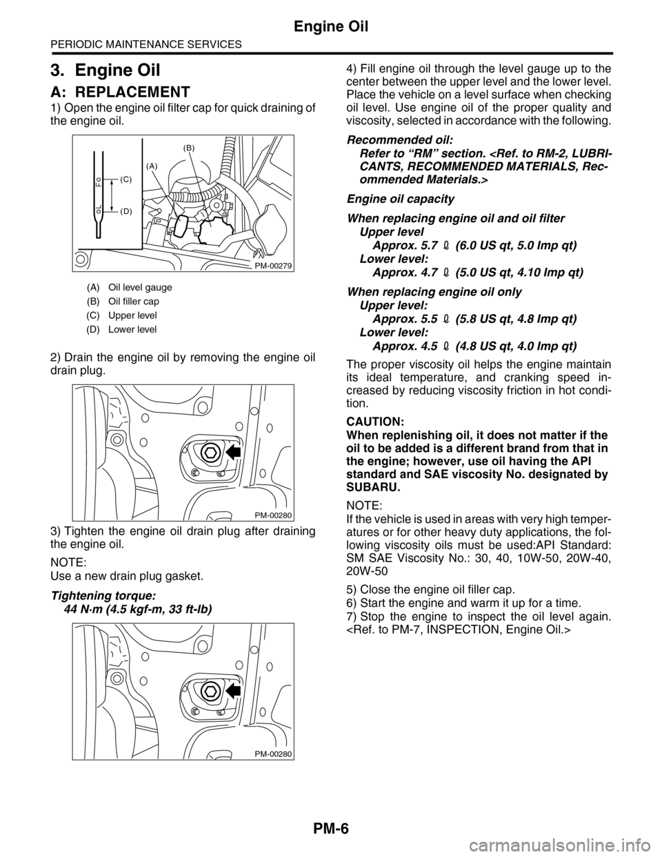
1) Open the engine oil filter cap for quick draining of
the engine oil.
2) Drain the engine oil by removing the engine oil
drain plug.
3) Tighten the engine oil drain plug after draining
the engine oil.
NOTE:
Use a new drain plug gasket.
Tightening torque:
44 N·m (4.5 kgf-m, 33 ft-lb)
4) Fill engine oil through the level gauge up to the
center between the upper level and the lower level.
Place the vehicle on a level surface when checking
oil level. Use engine oil of the proper quality and
viscosity, selected in accordance with the following.
Recommended oil:
Refer to “RM” section.
ommended Materials.>
Engine oil capacity
When replacing engine oil and oil filter
Upper level
Approx. 5.7 2 (6.0 US qt, 5.0 Imp qt)
Lower level:
Approx. 4.7 2 (5.0 US qt, 4.10 Imp qt)
When replacing engine oil only
Upper level:
Approx. 5.5 2 (5.8 US qt, 4.8 Imp qt)
Lower level:
Approx. 4.5 2 (4.8 US qt, 4.0 Imp qt)
The proper viscosity oil helps the engine maintain
its ideal temperature, and cranking speed in-
creased by reducing viscosity friction in hot condi-
tion.
CAUTION:
When replenishing oil, it does not matter if the
oil to be added is a different brand from that in
the engine; however, use oil having the API
standard and SAE viscosity No. designated by
SUBARU.
NOTE:
If the vehicle is used in areas with very high temper-
atures or for other heavy duty applications, the fol-
lowing viscosity oils must be used:API Standard:
SM SAE Viscosity No.: 30, 40, 10W-50, 20W-40,
20W-50
5) Close the engine oil filler cap.
6) Start the engine and warm it up for a time.
7) Stop the engine to inspect the oil level again.
(A) Oil level gauge
(B) Oil filler cap
(C) Upper level
(D) Lower level
PM-00279
(A)
(B)
(C)
(D)
PM-00280
PM-00280
Page 1999 of 2453
PM-16
Automatic Transmission Fluid
PERIODIC MAINTENANCE SERVICES
11. Automatic Transmission Fluid
A: INSPECTION
CAUTION:
The level of ATF varies with fluid temperature.
Pay attention to the fluid temperature when
checking ATF level.
1) Raise the ATF temperature by driving a distance
of 5 to 10 km (3 to 6 miles). Otherwise, idle the en-
gine to raise ATF temperature to 70 — 80°C (158
— 176°F) on Subaru Select Monitor.
TION, Subaru Select Monitor.>
2) Make sure the vehicle is level.
3) After selecting all positions (P, R, N, D), shift the
select lever in “P” range. Measure the ATF level
with engine idling for one or two minutes.
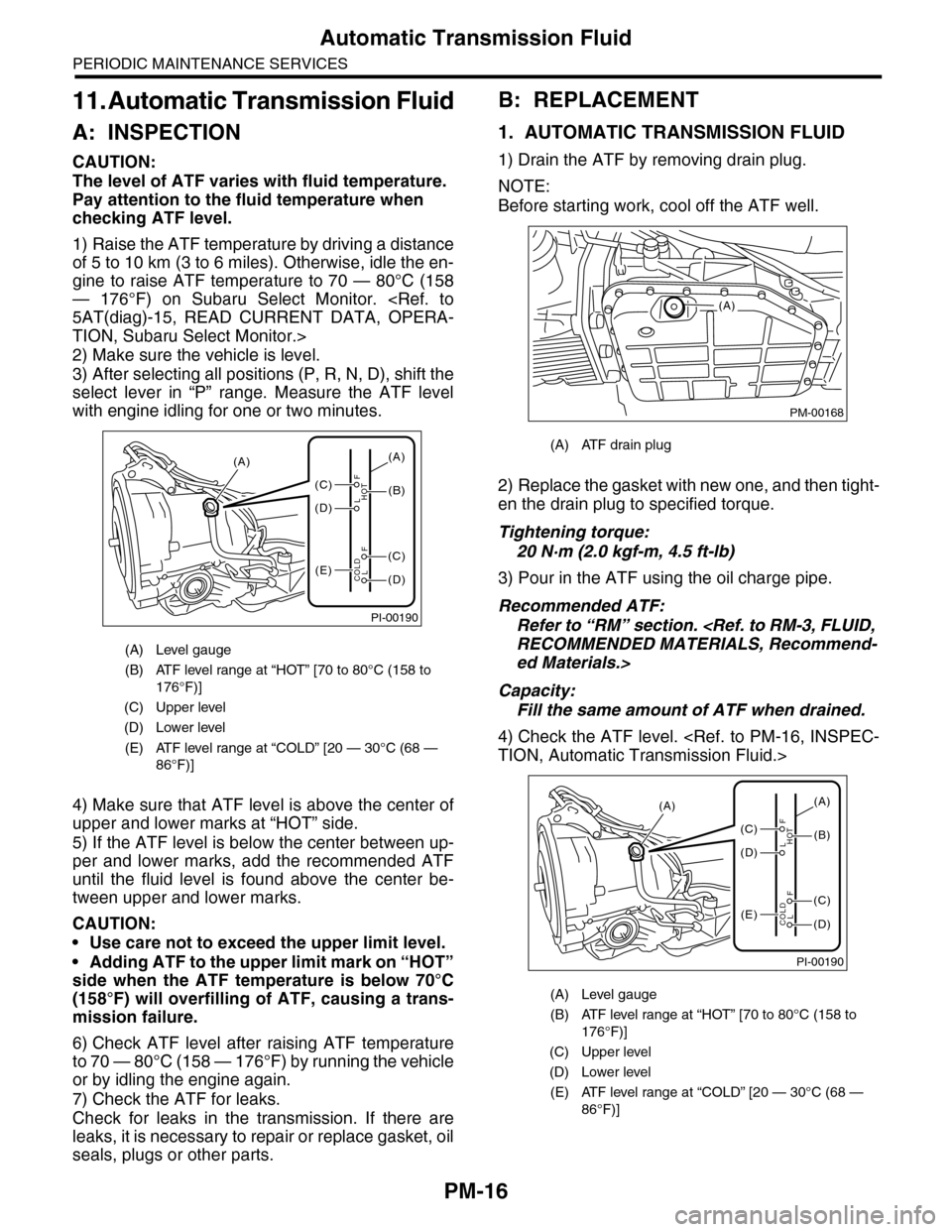
4) Make sure that ATF level is above the center of
upper and lower marks at “HOT” side.
5) If the ATF level is below the center between up-
per and lower marks, add the recommended ATF
until the fluid level is found above the center be-
tween upper and lower marks.
CAUTION:
•Use care not to exceed the upper limit level.
•Adding ATF to the upper limit mark on “HOT”
side when the ATF temperature is below 70°C
(158°F) will overfilling of ATF, causing a trans-
mission failure.
6) Check ATF level after raising ATF temperature
to 70 — 80°C (158 — 176°F) by running the vehicle
or by idling the engine again.
7) Check the ATF for leaks.
Check for leaks in the transmission. If there are
leaks, it is necessary to repair or replace gasket, oil
seals, plugs or other parts.
B: REPLACEMENT
1. AUTOMATIC TRANSMISSION FLUID
1) Drain the ATF by removing drain plug.
NOTE:
Before starting work, cool off the ATF well.
2) Replace the gasket with new one, and then tight-
en the drain plug to specified torque.
Tightening torque:
20 N·m (2.0 kgf-m, 4.5 ft-lb)
3) Pour in the ATF using the oil charge pipe.
Recommended ATF:
Refer to “RM” section.
ed Materials.>
Capacity:
Fill the same amount of ATF when drained.
4) Check the ATF level.
(A) Level gauge
(B) ATF level range at “HOT” [70 to 80°C (158 to
176°F)]
(C) Upper level
(D) Lower level
(E) ATF level range at “COLD” [20 — 30°C (68 —
86°F)]
PI-00190
(A)
(C)
(D)
(E)(D)
(C)
(B)
(A)
F
L
F
HOT
LCOLD
(A) ATF drain plug
(A) Level gauge
(B) ATF level range at “HOT” [70 to 80°C (158 to
176°F)]
(C) Upper level
(D) Lower level
(E) ATF level range at “COLD” [20 — 30°C (68 —
86°F)]
PM-00168
(A)
PI-00190
(A)
(C)
(D)
(E)(D)
(C)
(B)
(A)
F
L
F
HOT
LCOLD
Page 2013 of 2453
PM-30
Steering System (Power Steering)
PERIODIC MAINTENANCE SERVICES
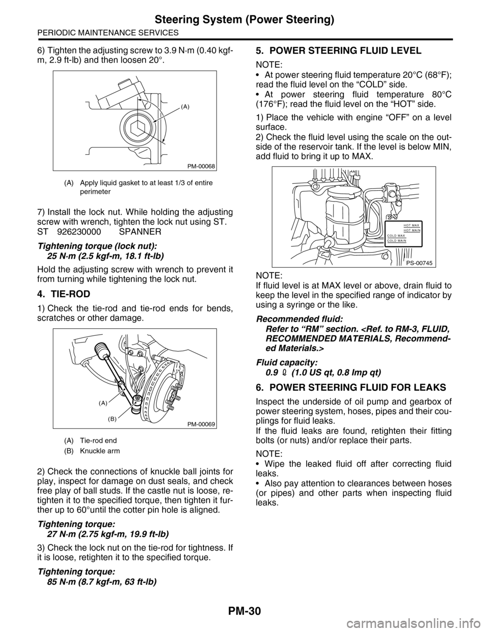
6) Tighten the adjusting screw to 3.9 N·m (0.40 kgf-
m, 2.9 ft-lb) and then loosen 20°.
7) Install the lock nut. While holding the adjusting
screw with wrench, tighten the lock nut using ST.
ST 926230000 SPANNER
Tightening torque (lock nut):
25 N·m (2.5 kgf-m, 18.1 ft-lb)
Hold the adjusting screw with wrench to prevent it
from turning while tightening the lock nut.
4. TIE-ROD
1) Check the tie-rod and tie-rod ends for bends,
scratches or other damage.
2) Check the connections of knuckle ball joints for
play, inspect for damage on dust seals, and check
free play of ball studs. If the castle nut is loose, re-
tighten it to the specified torque, then tighten it fur-
ther up to 60°until the cotter pin hole is aligned.
Tightening torque:
27 N·m (2.75 kgf-m, 19.9 ft-lb)
3) Check the lock nut on the tie-rod for tightness. If
it is loose, retighten it to the specified torque.
Tightening torque:
85 N·m (8.7 kgf-m, 63 ft-lb)
5. POWER STEERING FLUID LEVEL
NOTE:
•At power steering fluid temperature 20°C (68°F);
read the fluid level on the “COLD” side.
•At power steering fluid temperature 80°C
(176°F); read the fluid level on the “HOT” side.
1) Place the vehicle with engine “OFF” on a level
surface.
2) Check the fluid level using the scale on the out-
side of the reservoir tank. If the level is below MIN,
add fluid to bring it up to MAX.
NOTE:
If fluid level is at MAX level or above, drain fluid to
keep the level in the specified range of indicator by
using a syringe or the like.
Recommended fluid:
Refer to “RM” section.
ed Materials.>
Fluid capacity:
0.9 2 (1.0 US qt, 0.8 Imp qt)
6. POWER STEERING FLUID FOR LEAKS
Inspect the underside of oil pump and gearbox of
power steering system, hoses, pipes and their cou-
plings for fluid leaks.
If the fluid leaks are found, retighten their fitting
bolts (or nuts) and/or replace their parts.
NOTE:
•Wipe the leaked fluid off after correcting fluid
leaks.
•Also pay attention to clearances between hoses
(or pipes) and other parts when inspecting fluid
leaks.
(A) Apply liquid gasket to at least 1/3 of entire
perimeter
(A) Tie-rod end
(B) Knuckle arm
PM-00068
(A)
PM-00069
(A)
(B)
PS-00745
HOT MAXHOT MAINCOLD MAXCOLD MAIN
Page 2018 of 2453
5AT-2
General Description
AUTOMATIC TRANSMISSION
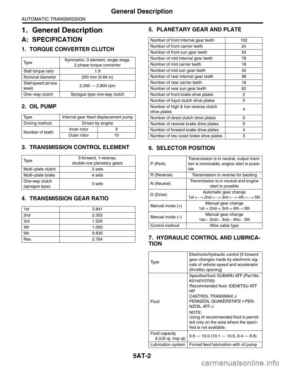
1. General Description
A: SPECIFICATION
1. TORQUE CONVERTER CLUTCH
2. OIL PUMP
3. TRANSMISSION CONTROL ELEMENT
4. TRANSMISSION GEAR RATIO
5. PLANETARY GEAR AND PLATE
6. SELECTOR POSITION
7. HYDRAULIC CONTROL AND LUBRICA-
TION
Ty p eSymmetric, 3 element, single stage,
2 phase torque converter
Stall torque ratio 1.9
Nominal diameter 250 mm (9.84 in)
Stall speed (at sea
level)2,300 — 2,800 rpm
One–way clutch Sprague type one-way clutch
Ty p e I n t e r n a l g e a r f i x e d d i s p l a c e m e n t p u m p
Driving method Driven by engine
Number of teethInner rotor 9
Outer rotor 10
Ty p e5-forward, 1-reverse,
double-row planetary gears
Multi–plate clutch 3 sets
Multi–plate brake 4 sets
One-way clutch
(sprague type)3 sets
1st 3.841
2nd 2.352
3rd 1.529
4th 1.000
5th 0.839
Rev. 2.764
Number of front internal gear teeth 102
Number of front carrier teeth 24
Number of front sun gear teeth 54
Number of mid internal gear teeth 78
Number of mid carrier teeth 18
Number of mid sun gear teeth 42
Number of rear internal gear teeth 98
Number of rear carrier teeth 18
Number of rear sun gear teeth 62
Number of front brake drive plates 2
Number of input clutch drive plates 5
Number of high & low reverse clutch
drive plates4
Number of direct clutch drive plates 5
Number of reverse brake drive plates 5
Number of forward brake drive plates 4
Number of low coast brake drive plates 3
P (Park)
Tr a n s m i s s i o n i s i n n e u t r a l , o u t p u t m e m -
ber is immovable, engine start is possi-
ble
R (Reverse) Transmission in reverse for backing
N (Neutral)Tr a n s m i s s i o n i s i n n e u t r a l a n d e n g i n e
start is possible
D (Drive)Automatic gear change
1st ←→ 2nd ←→ 3rd ←→ 4th ←→ 5th
Manual mode (+)Manual gear change
1st→ 2nd→ 3rd→ 4th→ 5th
Manual mode (–)Manual gear change
1st← 2nd← 3rd← 4th← 5th
Control method Wire cable type
Ty p e
Electronic/hydraulic control [5 forward
gear changes made by electronic sig-
nals of vehicle speed and accelerator
(throttle) opening]
Fluid
Specified fluid: SUBARU ATF (Part No.
K0140Y0700)
Recommended fluid: IDEMITSU ATF
HP
CASTROL TRANSMAX J
PENNZOIL QUAKERSTATE • PEN-
NZOIL ATF-J
NOTE:
Using of recommended fluid is permit-
ted only on the area where the speci-
fied is not available.
Fluid capacity
2(US qt, Imp qt)9.6 — 10.0 (10.1 — 10.6, 8.4 — 8.8)
Lubrication system Forced feed lubrication with oil pump
Page 2042 of 2453
5AT-26
Automatic Transmission Fluid
AUTOMATIC TRANSMISSION
2. Automatic Transmission Fluid
A: INSPECTION
NOTE:
The level of ATF varies with fluid temperature. Pay
attention to the ATF temperature when checking
ATF level.
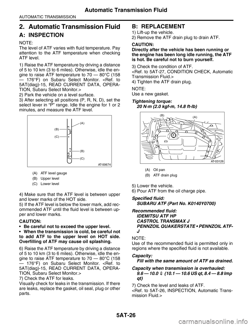
1) Raise the ATF temperature by driving a distance
of 5 to 10 km (3 to 6 miles). Otherwise, idle the en-
gine to raise ATF temperature to 70 — 80°C (158
— 176°F) on Subaru Select Monitor.
TION, Subaru Select Monitor.>
2) Park the vehicle on a level surface.
3) After selecting all positions (P, R, N, D), set the
select lever in “P” range. Idle the engine for 1 or 2
minutes, and measure the ATF level.
4) Make sure that the ATF level is between upper
and lower marks of the HOT side.
5) If the ATF level is below the lower mark, add rec-
ommended ATF until the fluid level is between up-
per and lower marks.
CAUTION:
•Be careful not to exceed the upper level.
•When the transmission is cold, be careful not
to add ATF to the upper level on HOT side.
Overfilling of ATF may cause oil splashing.
6) Raise the ATF temperature by driving a distance
of 5 to 10 km (3 to 6 miles). Otherwise, idle the en-
gine to raise ATF temperature to 70 — 80°C (158
— 176°F) on Subaru Select Monitor.
TION, Subaru Select Monitor.>
7) Check the ATF for leaks.
Visually check for leaks in the transmission. If there
are leaks, replace the gasket, oil seal, plug or other
parts.
B: REPLACEMENT
1) Lift-up the vehicle.
2) Remove the ATF drain plug to drain ATF.
CAUTION:
Directly after the vehicle has been running or
the engine has been long idle running, the ATF
is hot. Be careful not to burn yourself.
3) Check the condition of ATF.
4) Tighten the ATF drain plug.
NOTE:
Use a new gasket.
Tightening torque:
20 N·m (2.0 kgf-m, 14.8 ft-lb)
5) Lower the vehicle.
6) Pour ATF from the oil charge pipe.
Specified fluid:
SUBARU ATF (Part No. K0140Y0700)
Recommended fluid:
IDEMITSU ATF HP
CASTROL TRANSMAX J
PENNZOIL QUAKERSTATE • PENNZOIL ATF-
J
NOTE:
Use of the recommended fluid is permitted only in
regions where the specified fluid is not available.
Capacity:
Fill with the same amount of ATF as drained.
Capacity when transmission is overhauled:
9.6 — 10.0 2 ( 1 0 . 1 — 1 0 . 6 U S q t , 8 . 4 — 8 . 8 I m p
qt)
7) Check the level and leaks of ATF.
(A) ATF level gauge
(B) Upper level
(C) Lower level
AT-00674
COLDLF
HOTLF(C)
(C)
(B)
(B)
(A)
(A) Oil pan
(B) ATF drain plug
(A)
AT-03126
(B)