2009 SUBARU TRIBECA Oil pump
[x] Cancel search: Oil pumpPage 343 of 2453

AC-17
General Description
HVAC SYSTEM (HEATER, VENTILATOR AND A/C)
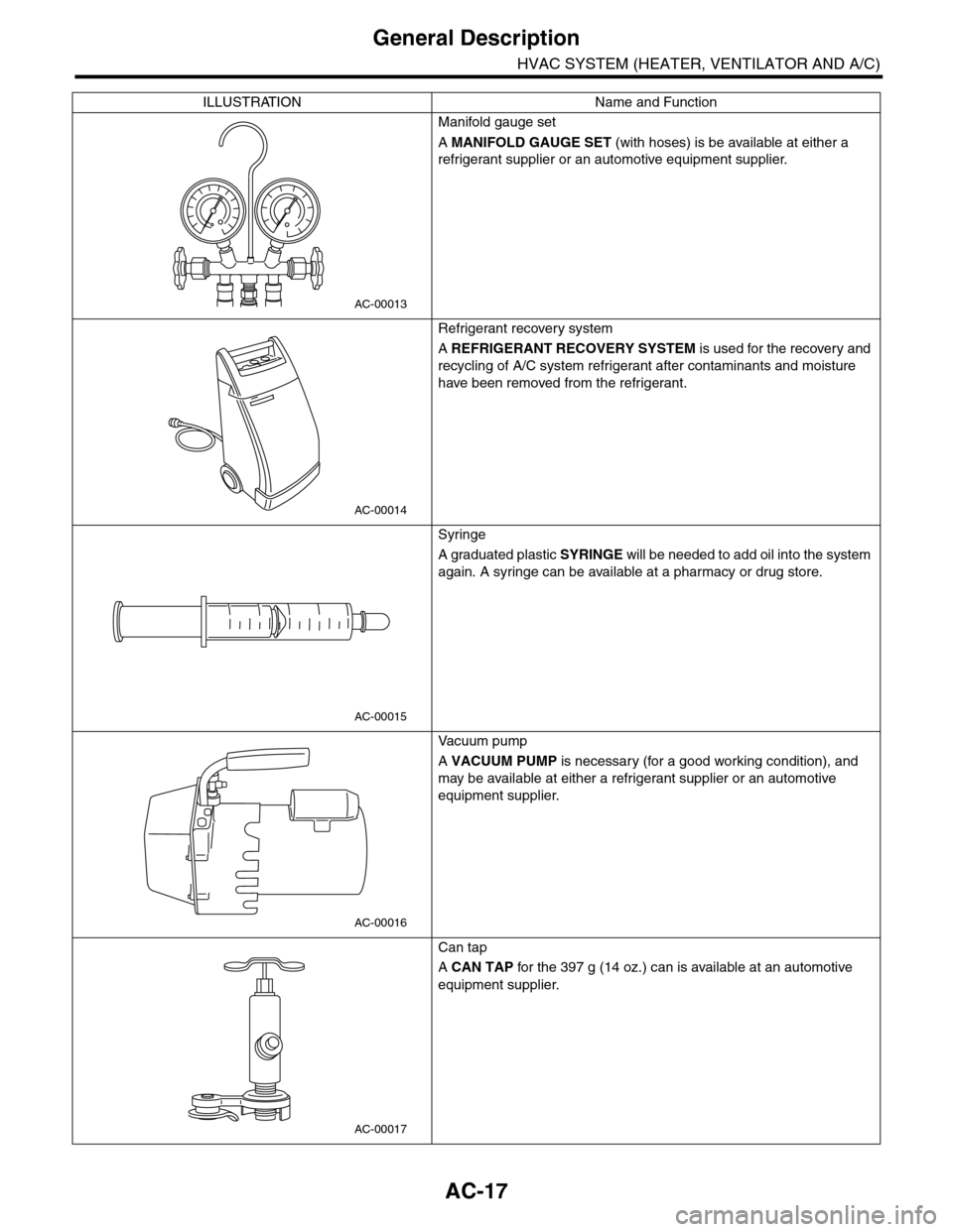
Manifold gauge set
A MANIFOLD GAUGE SET (with hoses) is be available at either a
refrigerant supplier or an automotive equipment supplier.
Refrigerant recovery system
A REFRIGERANT RECOVERY SYSTEM is used for the recovery and
recycling of A/C system refrigerant after contaminants and moisture
have been removed from the refrigerant.
Syringe
A graduated plastic SYRINGE will be needed to add oil into the system
again. A syringe can be available at a pharmacy or drug store.
Va c u u m p u m p
A VACUUM PUMP is necessary (for a good working condition), and
may be available at either a refrigerant supplier or an automotive
equipment supplier.
Can tap
A CAN TAP for the 397 g (14 oz.) can is available at an automotive
equipment supplier.
ILLUSTRATION Name and Function
AC-00013
AC-00014
AC-00015
AC-00016
AC-00017
Page 347 of 2453

AC-21
Refrigerant Charging Procedure
HVAC SYSTEM (HEATER, VENTILATOR AND A/C)
4. Refrigerant Charging Proce-
dure
A: PROCEDURE
CAUTION:
•During operation, be sure to wear protective
goggles and protective gloves.
•Before charging the refrigerant, evacuate the
system to remove small amounts of moisture
remaining in the system.
The moisture in the system can be completely
evacuated only under the minimum vacuum
level. The minimum vacuum level affects the
temperature in the system.
•The list below shows the vacuum values nec-
essary to boil water at various temperatures. In
addition, the vacuum levels indicated on the
gauge are approx. 3.3 kPa (25 mmHg, 0.98 inHg)
lower than those measured at 304.8 m (1,000 ft)
above sea level.
1) Close the valves on low-/high-pressure sides of
the manifold gauge.
2) Install the low-/high-pressure hoses to the corre-
sponding service ports on the vehicle.
3) Connect the center hose of the manifold gauge
set with the vacuum pump.
4) Carefully open the valves on the low-/high-pres-
sure sides to activate the vacuum pump.
5) After the low-pressure gauge reaches 100.0 kPa
(750 mmHg, 29.5 inHg) or higher, evacuate the
system for approx. 15 minutes. (Continue evacua-
tion).
6) After 15 minutes of evacuation, if the reading
shows 100.0 kPa (750 mmHg, 29.5 inHg) or higher,
close the valves on the both sides to stop the vac-
uum pump.
Va c u u m l eve l r e q u i r e d t o b o i l w a t e r ( a t s e a l eve l )
Te m p e r a t u r e Va c u u m
1.7°C (35°F) 100.9 kPa (757 mmHg, 29.8 inHg)
7.2°C (45°F) 100.5 kPa (754 mmHg, 29.7 inHg)
12.8°C (55°F) 99.8 kPa (749 mmHg, 29.5 inHg)
18.3°C (65°F) 99.2 kPa (744 mmHg, 29.3 inHg)
23.9°C (75°F) 98.5 kPa (739 mmHg, 29.1 inHg)
29.4°C (85°F) 97.2 kPa (729 mmHg, 28.7 inHg)
35°C (95°F) 95.8 kPa (719 mmHg, 28.3 inHg)
(A) Low-pressure gauge (Compound pressure
gauge)
(B) High-pressure gauge
(C) Close
AC-00023
(A) (B)
(C)(C)
(A) Low-pressure gauge (Compound pressure
gauge)
(B) High-pressure gauge
(C) Slowly open
(D) Vacuum pump turn on
(A) Low-pressure gauge (Compound pressure
gauge)
(B) High-pressure gauge
(C) Close
(D) Vacuum pump turn off
AC-00024
(A) (B)
(D)
(C)(C)
AC-00025
AC-00026
(A) (B)
(D)
(C)(C)
Page 882 of 2453

PS-2
General Description
POWER ASSISTED SYSTEM (POWER STEERING)
1. General Description
A: SPECIFICATION
Whole system
Minimum turning radius m (ft) 5.7 (18.7)
Steering angleInner wheel 37.0°±1.5°
Outer wheel 32.0°±1.5
Steering wheel diameter mm (in) 375 (14.76)
Lock to lock turn 3.44
Gearbox
Ty p e R a c k a n d P i n i o n , I n t e g r a l
Backlash 0 (Automatic adjusting)
Va l ve ( Po w e r s t e e r i n g s y s t e m ) R o t a r y va l ve
Pump
(Power steering
system)
Ty p e Va n e p u m p
Oil tank Installed on body
Specific outputcm3 (cu in)/rev.9.6 (0.586)
Relief pressurekPa (kg/cm2, psi)8,800 — 9,400 (90 — 96, 1,276 — 1,363)
Hydraulic fluid control Engine RPM sensitive
Hydraulic fluid2(US qt, Imp qt)1,000 rpm: 7.0 (7.4, 6.2)
3,000 rpm: 6.0 (6.3, 5.3)
RPM Range rpm 500 — 8,600
Direction of rotation Clockwise
Hydraulic oil
(Power steering
system)
Description ATF DEXRON III or equivalent
Capacity
2(US qt, Imp qt)
Oil tank 0.2 (0.2, 0.2)
Whole system 0.9 (1.0, 0.8)
Steering wheel Free play mm (in) 17 (0.67)
Steering shaftClearance between the steering wheel and
column covermm (in) 3.0 (0.12)
Steering gear-
box
(Power steering
system)
Sliding resistance N (kgf, lb)
400 (41, 90) or less
Difference between right and left sliding resistance:
Less than 20%
Rack shaft play in
the radial direction
Right–turn steering mm (in) 0.19 (0.0075) or less
Left–turn steering mm (in)Horizontal movement: 0.6 (0.024) or less
Ve r t i c a l m o v e m e n t : 0 . 4 ( 0 . 0 1 6 ) o r l e s s
Input shaft playIn radial direction mm (in) 0.18 (0.0071) or less
In axial direction mm (in) 0.27 (0.0106) or less
Rotation resistance N (kgf, lb)
Maximum allowable value: 10.5 (1.07, 2.36) or less
Difference between right and left sliding resistance:
Less than 20%
Oil Pump
(Power steering
system)
Pulley shaftRadial play mm (in) 0.2 (0.008) or less
Axial play mm (in) 0.6 (0.024) or less
PulleyDitch deflection mm (in) 1.0 (0.039) or less
Rotation resistance N (kgf, lb) 9.22 (0.94, 2.07) or less
Regular pressure (Unloaded)kPa (kg/cm2, psi)981 (10, 142) or less
Steering wheel
effort (Power
steering sys-
tem)
At standstill with engine idling on paved road N (kgf, lb) 29.4 (3.0, 6.6) or less
At standstill with engine stalled on paved
roadN (kgf, lb) 294.2 (30, 66.2) or less
Page 884 of 2453

PS-4
General Description
POWER ASSISTED SYSTEM (POWER STEERING)
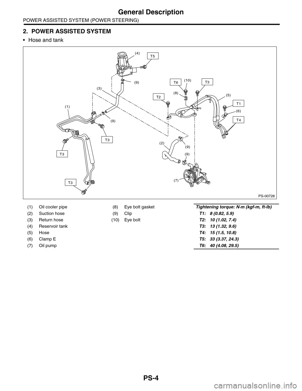
2. POWER ASSISTED SYSTEM
•Hose and tank
(1) Oil cooler pipe (8) Eye bolt gasketTightening torque: N·m (kgf-m, ft-lb)
(2) Suction hose (9) ClipT1: 8 (0.82, 5.9)
(3) Return hose (10) Eye boltT2: 10 (1.02, 7.4)
(4) Reservoir tank T3: 13 (1.32, 9.6)
(5) Hose T4: 15 (1.5, 10.8)
(6) Clamp E T5: 33 (3.37, 24.3)
(7) Oil pump T6: 40 (4.08, 29.5)
PS-00728
T2(8)
T6T3
(5)
T1
T4
(6)
T3
(1)
T3
(7)
T5(4)
T3
(2)
(9)
(9)
(3)
(9)
(9)(10)
Page 886 of 2453

PS-6
General Description
POWER ASSISTED SYSTEM (POWER STEERING)
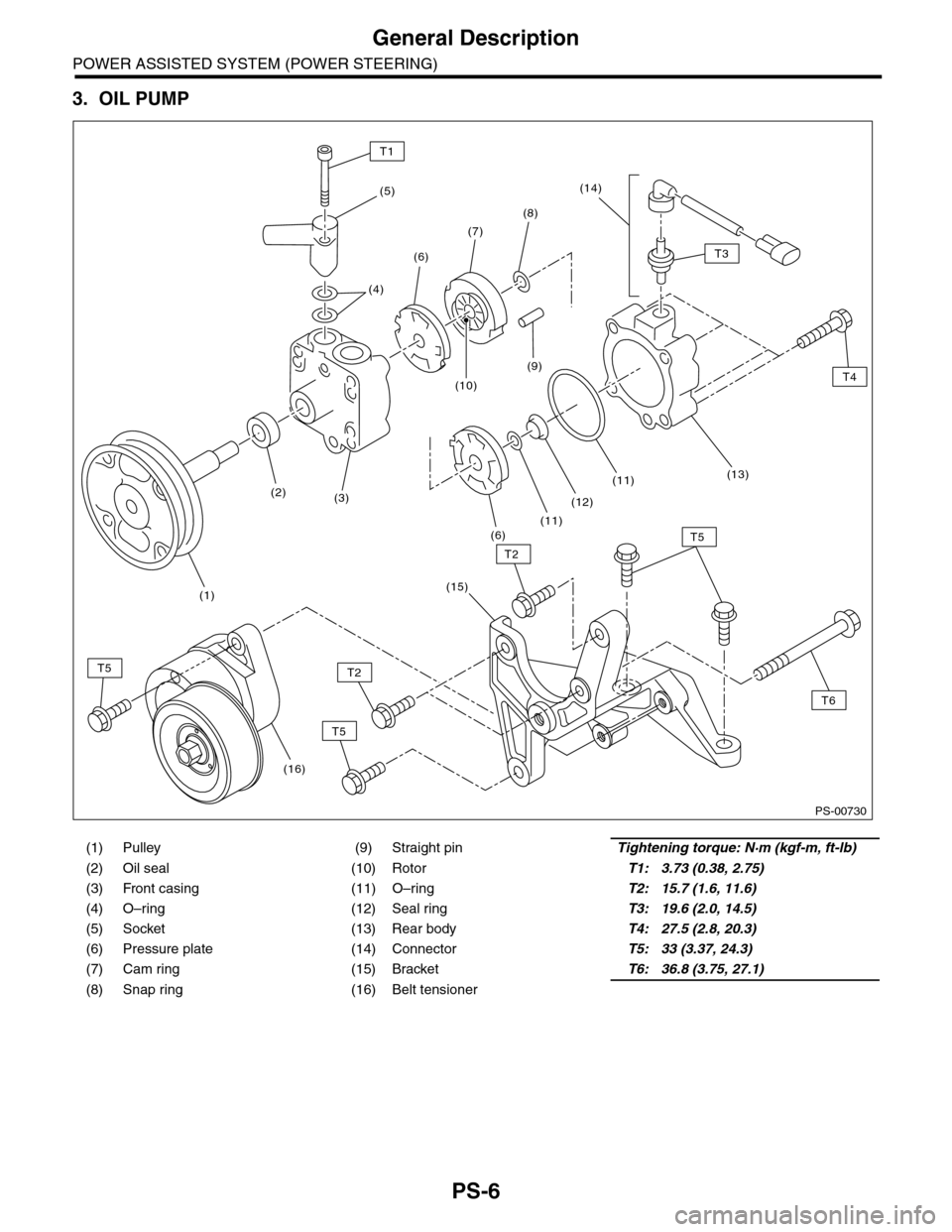
3. OIL PUMP
(1) Pulley (9) Straight pinTightening torque: N·m (kgf-m, ft-lb)
(2) Oil seal (10) RotorT1: 3.73 (0.38, 2.75)
(3) Front casing (11) O–ringT2: 15.7 (1.6, 11.6)
(4) O–ring (12) Seal ringT3: 19.6 (2.0, 14.5)
(5) Socket (13) Rear bodyT4: 27.5 (2.8, 20.3)
(6) Pressure plate (14) ConnectorT5: 33 (3.37, 24.3)
(7) Cam ring (15) BracketT6: 36.8 (3.75, 27.1)
(8) Snap ring (16) Belt tensioner
PS-00730
T1
(5)
(4)
(2)
(1)
(3)
(10)
(9)
(6)
(7)
(8)
(14)
(6)(11)
(12)
(11)(13)
T4
T6
T3
T5
T5
T5
T2
T2
(15)
(16)
Page 891 of 2453

PS-11
General Description
POWER ASSISTED SYSTEM (POWER STEERING)
34199AG090 INSTALLER &
REMOVER
•Used for installing oil seal of valve housing.
•Used for installing ball bearing of valve hous-
ing.
•Used for removing oil seal and ball bearing
from valve housing.
34199XA020 FORMER PISTON
44
•Used for forming seal ring of rack.
•Used with Guide G (26)(34199AG060).
34199XA000 INSTALLER 44 Used for pressing-fit oil seal of gearbox cylinder.
34199AE020 MOUNT Used to remove the oil pump.
34199AE030 INSTALLER Used for installing the oil seal to the oil pump.
ILLUSTRATION TOOL NUMBER DESCRIPTION REMARKS
ST34199AG090
ST34199XA020
ST34199XA000
ST34199AE020
ST34199AE030
Page 918 of 2453

PS-38
Pipe Assembly
POWER ASSISTED SYSTEM (POWER STEERING)
7) Disconnect the suction hose and pressure hose
from oil pump.
8) Disconnect the suction hose and return hose
from the reservoir tank.
9) Remove the oil cooler pipe.
10) Remove the hose bracket and take out the
hose assembly from vehicle.
B: INSTALLATION
1) Install in the reverse order of removal.
Tightening torque:
2) Fill with the specified fluid.
CAUTION:
Never start the engine before feeding the fluid
otherwise the vane pump might be seized.
3) Finally, check the clearance between pipes or
hoses as shown in the figure indicated in “General
Diagnostic Table”.
nostic Table.>
(1) Suction hose
(2) Pressure hose
(1) Reservoir tank
(2) Suction hose
(3) Return hose
PS-00736
(1)
(2)
PS-00737(3)
(2)
(1)
(1) Hose ASSY
(2) Hose bracket
PS-00738
PS-00739
(2)
(1)
Page 919 of 2453

PS-39
Pipe Assembly
POWER ASSISTED SYSTEM (POWER STEERING)
C: INSPECTION
Check all disassembled parts for wear, damage or other problems. Repair or replace the defective parts as
necessary.
CAUTION:
Although the surface layer materials of rubber hoses have excellent weathering resistance, heat re-
sistance and resistance for low temperature brittleness, they are likely to be damaged chemically by
brake fluid, battery electrolyte, engine oil and automatic transmission fluid and their service lives are
to be very shortened. Wipe off hoses immediately if any of these come into contact with the hoses.
Since resistances for heat or low temperature brittleness are gradually declining according to time
accumulation of hot or cold conditions for the hoses and their service lives are shortening accord-
ingly, it is necessary to perform careful inspection frequently when the vehicle is used in hot weather
areas, cold weather areas and a driving condition in which many steering operations are required in
short time.
Particularly continuous work of relief valve over 5 seconds causes to reduce service lives of the hos-
es, the oil pump, the fluid, etc. due to over heat.
Par t Maintenance par ts Corrective action
Pipe
•O–ring fitting surface damage
•Nut damage
•Pipe damage
Replace with a new part.
Clamp • Loose clamps Replace with a new part.
Hose
•Flare surface damage
•Flare nut damage
•Outer surface cracks
•Outer surface wear
•Clip damage
•End coupling or adapter for deformation
Replace with a new part.
Tr o u b l e P o s s i b l e c a u s e C o r r e c t i v e a c t i o n
Pressure hose burst
Excessive holding time of relief status Instruct customers.
Malfunction of the relief valve Replace the oil pump.
Poor cold character istic of fluid R eplace fluid.
Disconnection of the return
hose
Improper connection Repair.
Loosening of the clip Retighten.
Poor cold character istic of fluid R eplace fluid.
Fluid slightly leaking out of
hose
Wrong layout, tensioned Replace the hose.
Excessive play of engine due to deterioration of
engine mounting rubberReplace the parts if defective.
Improper stop position of pitching stopper Replace the parts if defective.
Crack on hose
Excessive holding time of relief statusReplace.
Instruct customers.
Excessive tightening torque for return hose clip Replace.
Power steer ing fluid, engine oil, electrolyte adhere
on the hose surface
Replace.
Be careful during service work.
To o m a n y u s e s i n e x t r e m e l y c o l d w e a t h e rReplace.
Instruct customers.