Page 233 of 2453

EB-14
Front Hood
EXTERIOR BODY PANELS
4) Remove the front fender.
MOVAL, Front Fender.>
5) Remove the bolts of front hood hinge.
5. FRONT HOOD STRIKER
Refer to the front hood lock assembly of SL section.
Assembly.>
6. FRONT HOOD PANEL
1) Remove the front hood insulator.
2) Open the front hood to remove the window
washer hose.
3) Remove the front hood weather strip.
4) Remove the hood lock assembly.
sembly.>
5) Remove the window washer hose and nozzle.
zle.>
6) Remove the front hood damper.
7) Remove the bolt, and remove the front hood
panel from the front hood hinge.
B: INSTALLATION
Install in the reverse order of removal.
NOTE:
Be careful not to catch the window washer hose in.
Tightening torque:
Refer to “COMPONENT” of “General Descrip-
tion”.
NENT, General Description.>
C: ADJUSTMENT
1) Adjust the clearance between front hood panel
and front fender panel. Clearance must be equal at
both sides. For the dimension of clearance, refer to
“SPECIFICATION” in “General Description”.
to EB-2, SPECIFICATION, General Description.>
2) Use the hinge mounting bolts to align the front
hood longitudinal and lateral position.
3) Adjust the height at the front end of hood.
to SL-44, ADJUSTMENT, Front Hood Lock Assem-
bly.>
4) Rotate the hood buffer to adjust lateral height.
D: DISPOSAL
For the disposal procedures of front hood damper
stay, refer to the disposal procedures of rear gate
damper stay.
Gate.>
EB-00286
EB-00285
EB-00285
EB-00287
Page 470 of 2453

LAN(diag)-14
Subaru Select Monitor
LAN SYSTEM (DIAGNOSTICS)
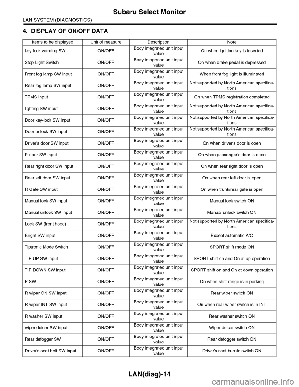
4. DISPLAY OF ON/OFF DATA
Items to be displayed Unit of measure Description Note
key-lock warning SW ON/OFFBody integrated unit input
valueOn when ignition key is inserted
Stop Light Switch ON/OFFBody integrated unit input
valueOn when brake pedal is depressed
Fr o nt fog la mp S W i n pu t O N/O FFBody integrated unit input
valueWhen front fog light is illuminated
Rear fog lamp SW input ON/OFFBody integrated unit input
value
Not supported by North American specifica-
tions
TPMS Input ON/OFFBody integrated unit input
valueOn when TPMS registration completed
lighting SW input ON/OFFBody integrated unit input
value
Not supported by North American specifica-
tions
Door key-lock SW input ON/OFFBody integrated unit input
value
Not supported by North American specifica-
tions
Door unlock SW input ON/OFFBody integrated unit input
value
Not supported by North American specifica-
tions
Driver’s door SW input ON/OFFBody integrated unit input
valueOn when driver’s door is open
P-door SW input ON/OFFBody integrated unit input
valueOn when passenger’s door is open
Rear right door SW input ON/OFFBody integrated unit input
valueOn when rear right door is open
Rear left door SW input ON/OFFBody integrated unit input
valueOn when rear left door is open
R Gate SW input ON/OFFBody integrated unit input
valueOn when trunk/rear gate is open
Manual lock SW input ON/OFFBody integrated unit input
valueManual lock switch ON
Manual unlock SW input ON/OFFBody integrated unit input
valueManual unlock switch ON
Lock SW (front hood) ON/OFFBody integrated unit input
value
Not supported by North American specifica-
tions
Bright SW input ON/OFFBody integrated unit input
valueExcept automatic A/C
Tiptronic Mode Switch ON/OFFBody integrated unit input
valueSPORT shift mode ON
TIP UP SW input ON/OFFBody integrated unit input
valueSPORT shift on and On at up operation
TIP DOWN SW input ON/OFFBody integrated unit input
valueSPORT shift on and On at down operation
P SW ON/OFFBody integrated unit input
valueOn when shift range is in parking
R wiper ON SW input ON/OFFBody integrated unit input
valueRear wiper switch ON
R wiper INT SW input ON/OFFBody integrated unit input
valueOn when rear wiper switch is in INT
R washer SW input ON/OFFBody integrated unit input
valueRear washer switch ON
wiper deicer SW input ON/OFFBody integrated unit input
valueWiper deicer switch ON
Rear defogger SW ON/OFFBody integrated unit input
valueRear defogger switch ON
Driver’s seat belt SW input ON/OFFBody integrated unit input
valueDriver’s seat buckle switch ON
Page 547 of 2453
LI-14
Front Turn Signal Light Bulb
LIGHTING SYSTEM
12.Front Turn Signal Light Bulb
A: REMOVAL
1) Open the front hood.
2) Turn the socket (A) and remove the front turn
signal light bulb.
B: INSTALLATION
Install in the reverse order of removal.
C: INSPECTION
1) Visually check the bulb for blow out.
2) Check the bulb specification.
tion.>
3) If NG, replace the bulb with a new one.
Page 549 of 2453
LI-16
Front Side Marker Light Bulb
LIGHTING SYSTEM
14.Front Side Marker Light Bulb
A: REMOVAL
1) Open the front hood.
2) Turn the socket (A) and remove the front turn
signal light bulb.
B: INSTALLATION
Install in the reverse order of removal.
C: INSPECTION
1) Visually check the bulb for blow out.
2) Check the bulb specification.
tion.>
3) If NG, replace the bulb with a new one.
LI-00508
(A)
Page 633 of 2453
SL-4
General Description
SECURITY AND LOCKS
3. FRONT HOOD LOCK AND REMOTE OPENERS
(A) Fuel lid (B) Hood
(1) Front hood lock assembly (6) Pull handle ASSYTightening torque: N·m (kgf-m, ft-lb)
(2) Cable assembly, front hood (7) Hood operation leverT1: 33.0 (3.36, 24.3)
(3) Cable assembly, fuel T2: 7.5 (0.76, 5.5)
(4) Pull lever T3: 4.5 (0.46, 3.3)
(5) Cover T4: 25 (2.55, 18.4)
SL-00438
(2)
T1
T1
(6)
(3)
(7)
(1)
(5)
(A)(B)
(4)
T2
T3T4
Page 658 of 2453

SL-29
Security System
SECURITY AND LOCKS
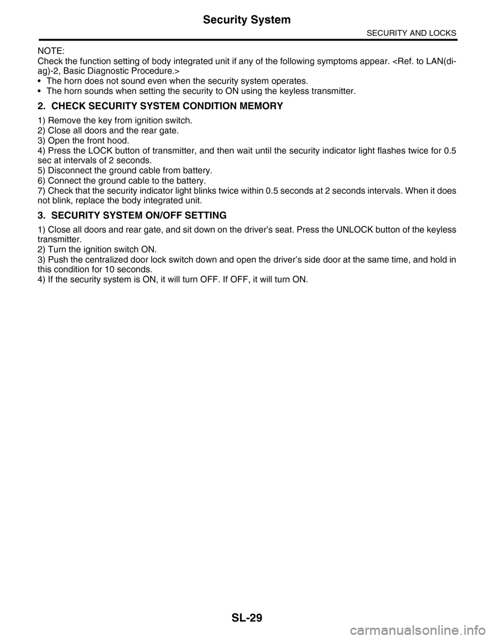
NOTE:
Check the function setting of body integrated unit if any of the following symptoms appear.
ag)-2, Basic Diagnostic Procedure.>
•The horn does not sound even when the security system operates.
•The horn sounds when setting the security to ON using the keyless transmitter.
2. CHECK SECURITY SYSTEM CONDITION MEMORY
1) Remove the key from ignition switch.
2) Close all doors and the rear gate.
3) Open the front hood.
4) Press the LOCK button of transmitter, and then wait until the security indicator light flashes twice for 0.5
sec at intervals of 2 seconds.
5) Disconnect the ground cable from battery.
6) Connect the ground cable to the battery.
7) Check that the security indicator light blinks twice within 0.5 seconds at 2 seconds intervals. When it does
not blink, replace the body integrated unit.
3. SECURITY SYSTEM ON/OFF SETTING
1) Close all doors and rear gate, and sit down on the driver’s seat. Press the UNLOCK button of the keyless
transmitter.
2) Turn the ignition switch ON.
3) Push the centralized door lock switch down and open the driver’s side door at the same time, and hold in
this condition for 10 seconds.
4) If the security system is ON, it will turn OFF. If OFF, it will turn ON.
Page 673 of 2453
SL-44
Front Hood Lock Assembly
SECURITY AND LOCKS
15.Front Hood Lock Assembly
A: REMOVAL
1) Open the front hood.
2) Remove the engine front cover.
3) Remove the bolts, and then detach the front
hood lock assembly.
4) Remove the cable from lock assembly.
B: INSTALLATION
Install in the reverse order of removal.
NOTE:
•Apply grease to the movable part.
•Make sure the cable works correctly after instal-
lation.
C: ADJUSTMENT
Loosen the bolt, and adjust the lock assembly while
moving it up and down.
D: INSPECTION
1) Check the striker for deformation or abnormal
wear.
2) Check the safety lever for improper movement.
3) Check other levers and springs for rust formation
or unsmooth movement.
SL-00450
SL-00451
Page 674 of 2453

SL-45
Remote Openers
SECURITY AND LOCKS
16.Remote Openers
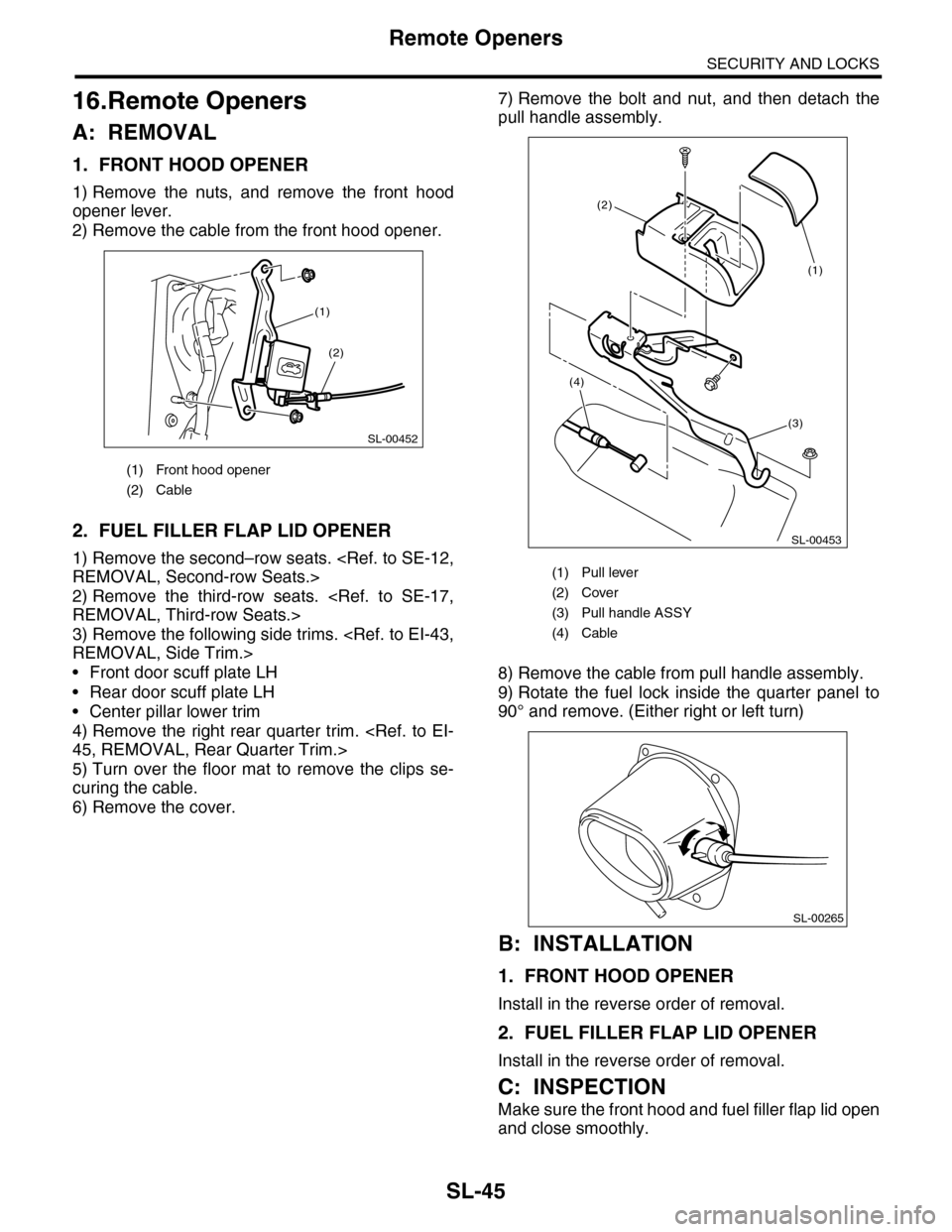
A: REMOVAL
1. FRONT HOOD OPENER
1) Remove the nuts, and remove the front hood
opener lever.
2) Remove the cable from the front hood opener.
2. FUEL FILLER FLAP LID OPENER
1) Remove the second–row seats.
REMOVAL, Second-row Seats.>
2) Remove the third-row seats.
REMOVAL, Third-row Seats.>
3) Remove the following side trims.
REMOVAL, Side Trim.>
•Front door scuff plate LH
•Rear door scuff plate LH
•Center pillar lower trim
4) Remove the right rear quarter trim.
45, REMOVAL, Rear Quarter Trim.>
5) Turn over the floor mat to remove the clips se-
curing the cable.
6) Remove the cover.
7) Remove the bolt and nut, and then detach the
pull handle assembly.
8) Remove the cable from pull handle assembly.
9) Rotate the fuel lock inside the quarter panel to
90° and remove. (Either right or left turn)
B: INSTALLATION
1. FRONT HOOD OPENER
Install in the reverse order of removal.
2. FUEL FILLER FLAP LID OPENER
Install in the reverse order of removal.
C: INSPECTION
Make sure the front hood and fuel filler flap lid open
and close smoothly.
(1) Front hood opener
(2) Cable
SL-00452
(2)
(1)
(1) Pull lever
(2) Cover
(3) Pull handle ASSY
(4) Cable
SL-00453
(3)
(2)
(4)
(1)
SL-00265