2009 SUBARU TRIBECA engine sensor diagram
[x] Cancel search: engine sensor diagramPage 192 of 2453
ET-6
Navigation System
ENTERTAINMENT
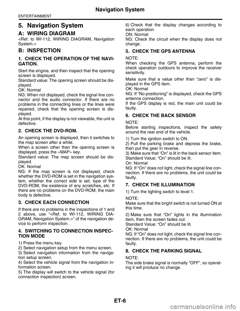
5. Navigation System
A: WIRING DIAGRAM
B: INSPECTION
1. CHECK THE OPERATION OF THE NAVI-
GATION.
Start the engine, and then inspect that the opening
screen is displayed.
Standard value: The opening screen should be dis-
played.
OK: Normal
NG: When not displayed, check the signal line con-
nector and the audio connector. If there are no
problems in the connecting lines or the lines were
repaired, check that the opening screen is dis-
played.
At this point, if the display is not viewable, the unit is
defective.
2. CHECK THE DVD-ROM.
An opening screen is displayed, then it switches to
the map screen after a while.
When a screen other than the opening screen is
displayed, press the «MAP» key.
Standard value: The map screen should be dis-
played.
OK: Normal
NG: If the map screen is not displayed, check
whether the DVD-ROM is set in the navigation sys-
tem, whether the correct side is set, type of the
DVD-ROM, the existence of any scratches, etc. If
there are no problems on the DVD-ROM, the main
body is defective.
3. CHECK EACH CONNECTION
If there are no problems in the inspections of 1 and
2 above, use “
vice to perform inspection.
4. SWITCHING TO CONNECTION INSPEC-
TION MODE
1) Press the menu key.
2) Select navigation setup from the menu screen.
3) Select navigation information from the naviga-
tion setup screen.
4) Select the vehicle signal from the navigation in-
formation screen.
5) The display will switch to the vehicle signal (for
connection inspection) screen.
6) Check that the display changes according to
each operation
ON: Normal
NG: Check the circuit when the display does not
change.
5. CHECK THE GPS ANTENNA
NOTE:
When checking the GPS antenna, perform the
check operation outdoors to improve the receiver
sensitivity.
Make sure that a value other than “zero” is dis-
played in the GPS item.
OK: Normal
NG: If “No positioning” is displayed, check the GPS
antenna connection.
If the GPS display is red, the main unit could be
faulty.
6. CHECK THE BACK SENSOR
NOTE:
Before starting inspections, inspect the safety
around the rear end of the vehicle.
1) Turn the ignition switch to ON.
2) Pull the parking brake and depress the brake,
then put the gear in reverse.
3) Make sure that “On” is lit in the back sensor item.
Standard Value: “On” should be lit.
On: Normal
NG: If “On” does not light, check the signal line con-
nection. If there are no problems, the unit could be
faulty.
7. CHECK THE ILLUMINATION
1) Turn the lighting switch to level 1.
NOTE:
Make sure that the bright switch is not turned ON at
this time.
2) Make sure that “On” lights in the illumination
item, then the screen fades out.
Standard Value: “On” should be lit.
OK: Normal
NG: If “On” does not light, check the signal line con-
nection. If there are no problems, the unit could be
faulty.
8. CHECK THE PARKING SIGNAL
NOTE:
The side brake signal is normally “OFF”, so operat-
ing it will produce no change.
Page 509 of 2453

LAN(diag)-53
Diagnostic Procedure with Diagnostic Trouble Code (DTC)
LAN SYSTEM (DIAGNOSTICS)
K: DTC B0211 CAN-HS ECM DATA ABNORMAL
DTC DETECTING CONDITION:
Defective data from ECM.
TROUBLE SYMPTOM:
“Er HC” or “Er EG” is displayed in odo/trip meter.
WIRING DIAGRAM:
VDCCM & H/U
B310
B20B30
BODY INTEGRATEDUNIT
B280B:
TCM
B54A:
23
B359
YAW R AT ESENSOR
34
20
B231
21
STEERING ANGLESENSOR
B231
1234
B54A:
12 7 8 9563410 11 1219 20 2113 14 15 16 17 1822 23 24
B136B310
B280B:
5467821931022 23111213141524 25 26 2716171828 29192021 30
ECM
B136
27
35
A3A4
TWISTED PAIR LINE
12345678910 11 12 13 14
15 16 17 18 19 2021 22 23 24 25 26 27 2829 30 31 32 33 3435 36 37 38 39403940
27 28394016101112131415252430
9871718192028212223293231
123456
2726333435
LAN00191
Step Check Yes No
1CHECK ECM.
Read the DTC of ECM using Subaru Select
Monitor.
(DTC).>
Is DTC other than “CAN com-
munication” displayed?
Pe r for m t h e d ia g -
nosis according to
DTC.
Replace the ECM.
Engine Control
Module (ECM).>
Page 1007 of 2453
VDC(diag)-15
Control Module I/O Signal
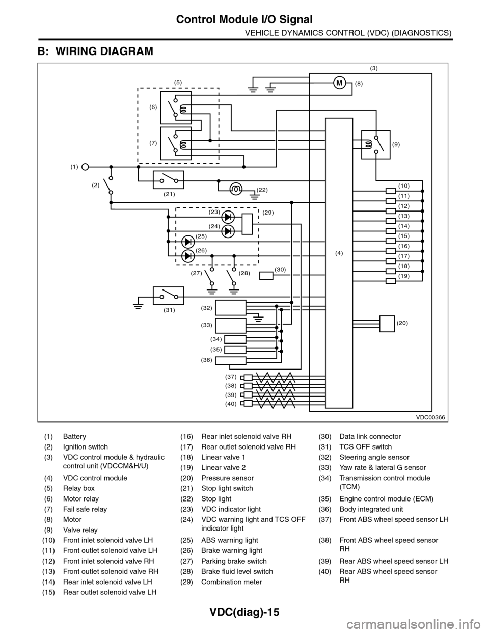
VEHICLE DYNAMICS CONTROL (VDC) (DIAGNOSTICS)
B: WIRING DIAGRAM
(1) Battery (16) Rear inlet solenoid valve RH (30) Data link connector
(2) Ignition switch (17) Rear outlet solenoid valve RH (31) TCS OFF switch
(3) VDC control module & hydraulic
control unit (VDCCM&H/U)
(18) Linear valve 1 (32) Steering angle sensor
(19) Linear valve 2 (33) Yaw rate & lateral G sensor
(4) VDC control module (20) Pressure sensor (34)
Tr a n s m i s s i o n c o n t r o l m o d u l e
(TCM)(5) Relay box (21) Stop light switch
(6) Motor relay (22) Stop light (35) Engine control module (ECM)
(7) Fail safe relay (23) VDC indicator light (36) Body integrated unit
(8) Motor (24) VDC warning light and TCS OFF
indicator light
(37)
Fr o nt A B S w he e l sp ee d se n so r L H
(9) Valve relay
(10) Front inlet solenoid valve LH (25) ABS warning light (38)
Fr o nt A B S w he e l sp e ed se n so r
RH(11) Front outlet solenoid valve LH (26) Brake warning light
(12) Front inlet solenoid valve RH (27) Parking brake switch (39) Rear ABS wheel speed sensor LH
(13) Front outlet solenoid valve RH (28) Brake fluid level switch (40) Rear ABS wheel speed sensor
RH(14) Rear inlet solenoid valve LH (29) Combination meter
(15) Rear outlet solenoid valve LH
VDC00366
M
(17)(4)(16)
(19)
(20)
(18)
(38)
(37)
(32)
(33)
(36)
(34)
(35)
(40)
(39)
(15)
(14)
(13)
(12)
(7)
(22)(21)
(31)
(23)(29)
(24)
(25)
(26)
(27) (28)(30)
(1)
(2)
(6)
(11)
(10)
(9)
(8)
(3)
(5)
Page 1024 of 2453
VDC(diag)-32
Warning Light Illumination Pattern
VEHICLE DYNAMICS CONTROL (VDC) (DIAGNOSTICS)
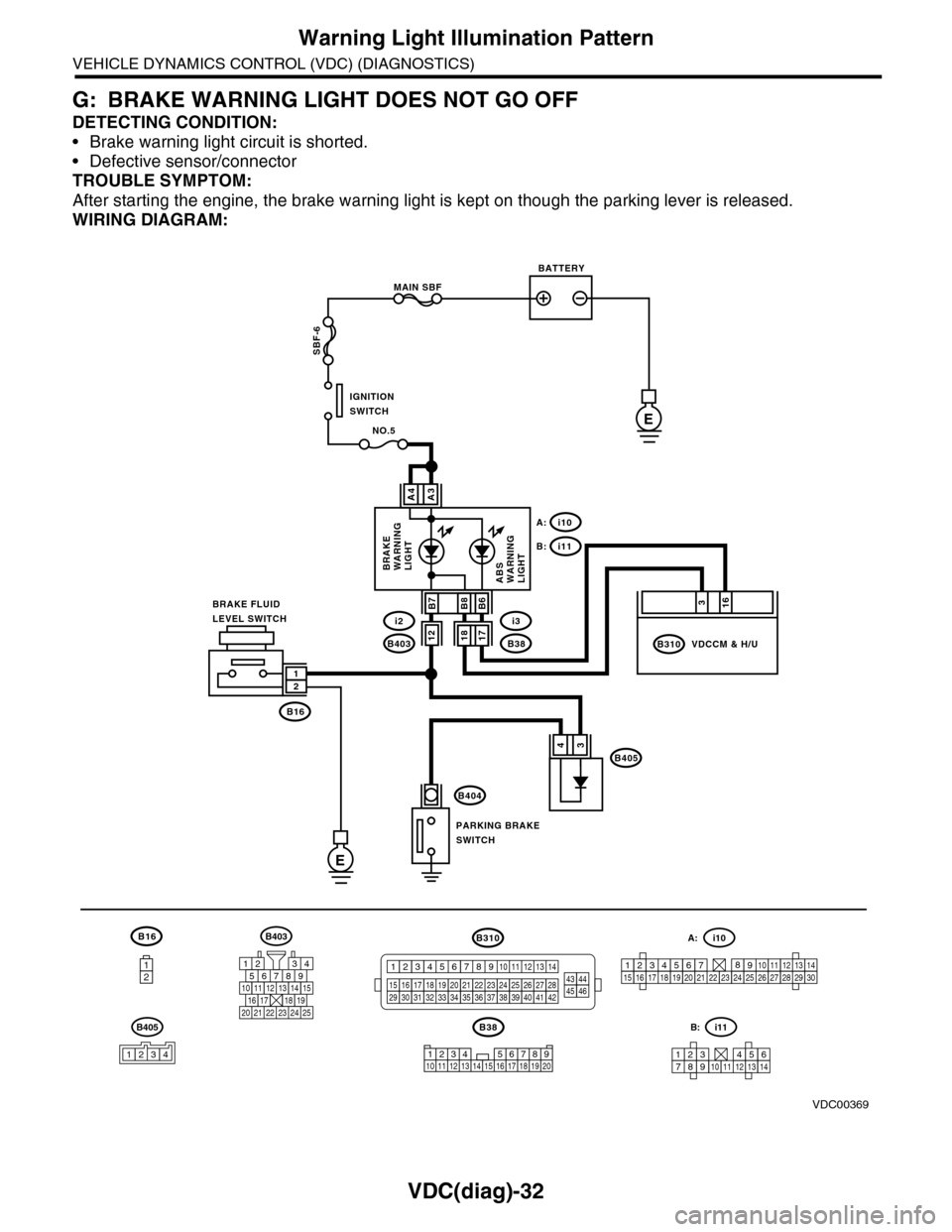
G: BRAKE WARNING LIGHT DOES NOT GO OFF
DETECTING CONDITION:
•Brake warning light circuit is shorted.
•Defective sensor/connector
TROUBLE SYMPTOM:
After starting the engine, the brake warning light is kept on though the parking lever is released.
WIRING DIAGRAM:
B16
12
B38
E
MAIN SBF
SBF-6
E
NO.5
B16
B404
A3A4
12
34B405
1234 5678910 11 12 13 14 15 16 17 18 19 20
BATTERY
IGNITIONSWITCH
BRAKE FLUIDLEVEL SWITCH
PARKING BRAKESWITCH
BRAKEWARNINGLIGHTABSWARNINGLIGHT
316
B310B38
i3
i10A:
i11B:
VDCCM & H/U
B8
1817B403
i2B7B6
VDC00369
12
B405
1234
B403
567821943
10
2422 23 25
1112131415161718192021
B310
1234
1516171819202122232425262728293031323334353637383940414245464344568910 11 12 13 147
1234567891011121314
i11B:
123456789101112131415161718192021222324252627282930
i10A:
Page 1222 of 2453
EN(H6DO)(diag)-61
Diagnostics for Engine Starting Failure
ENGINE (DIAGNOSTICS)
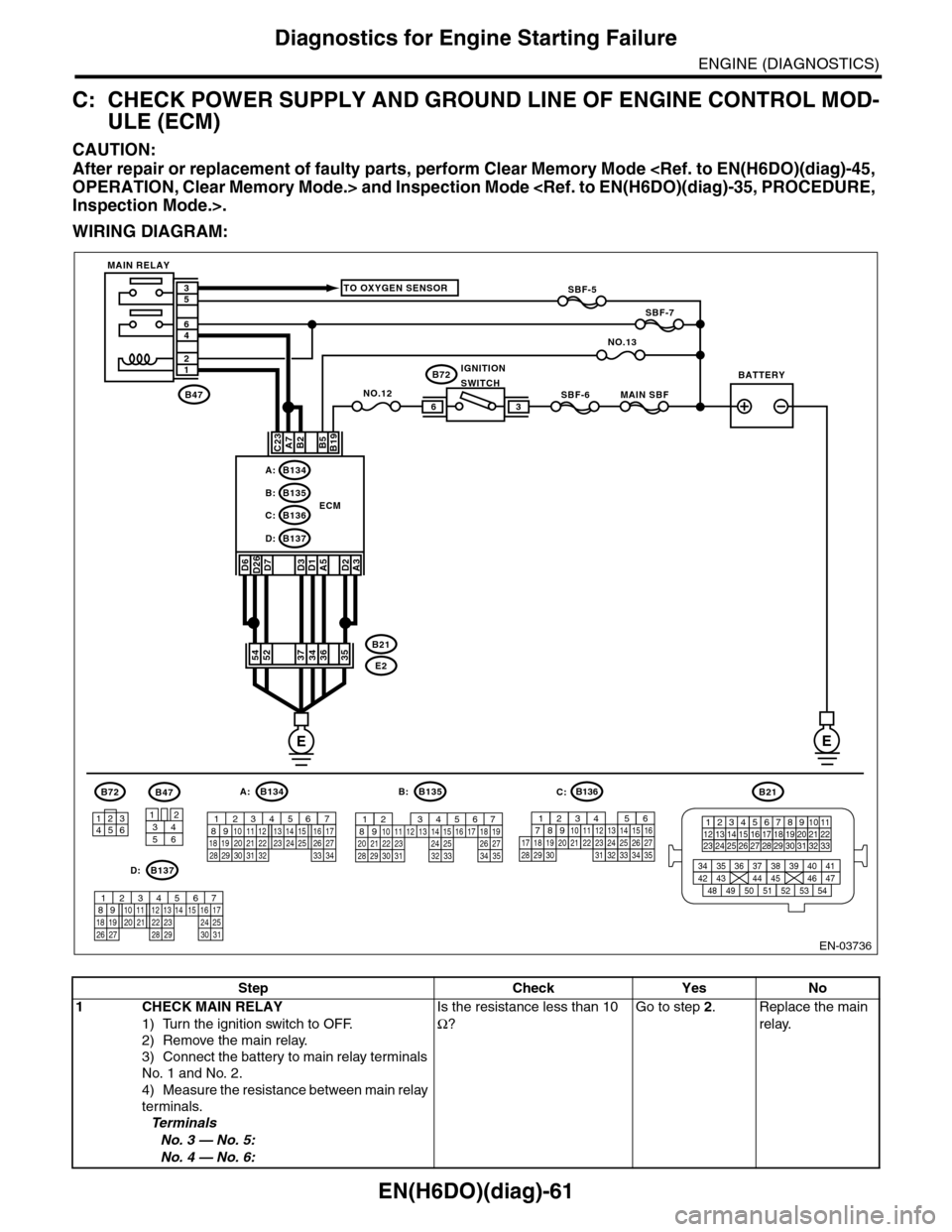
C: CHECK POWER SUPPLY AND GROUND LINE OF ENGINE CONTROL MOD-
ULE (ECM)
CAUTION:
After repair or replacement of faulty parts, perform Clear Memory Mode
WIRING DIAGRAM:
EN-03736
SBF-6MAIN SBF
SBF-7
B72
B2A7C23
D7D3D1A5
B5B19
NO.12B47
E2
B21
12
46
53
ECM
EE
36
B134A:
D:B137
B135B:
B136C:
A3
52373634
3412
56
B47
TO OXYGEN SENSOR
NO.13
D2
35
B21
123412131415567816171819910 1120212223 24 25 2627 28 29 3031 32 33
3534 37363938 41404342 4445 47464948 51505352 54
B72
134562
B134
56 7821943102422 23 2511 12 13 14 1526 2728
16 1718 19 20 2133 34293230 31
A:B135
567821943102422 23 2511 12 13 14 1526 2728
16 17 18 1920 2129 30 31 32 33 34 35
B:
B137
5678219431022 2311 12 13 14 1524 2526
16 1718 19 20 2127 28 29 30 31
D:
SBF-5
D6D26
54
MAIN RELAY
BATTERYIGNITIONSWITCH
B136
16101112131415252430
9871718192028212223293231
123456
2726333435
C:
Step Check Yes No
1CHECK MAIN RELAY
1) Turn the ignition switch to OFF.
2) Remove the main relay.
3) Connect the battery to main relay terminals
No. 1 and No. 2.
4) Measure the resistance between main relay
terminals.
Te r m i n a l s
No. 3 — No. 5:
No. 4 — No. 6:
Is the resistance less than 10
Ω?
Go to step 2.Replace the main
relay.
Page 1224 of 2453
EN(H6DO)(diag)-63
Diagnostics for Engine Starting Failure
ENGINE (DIAGNOSTICS)
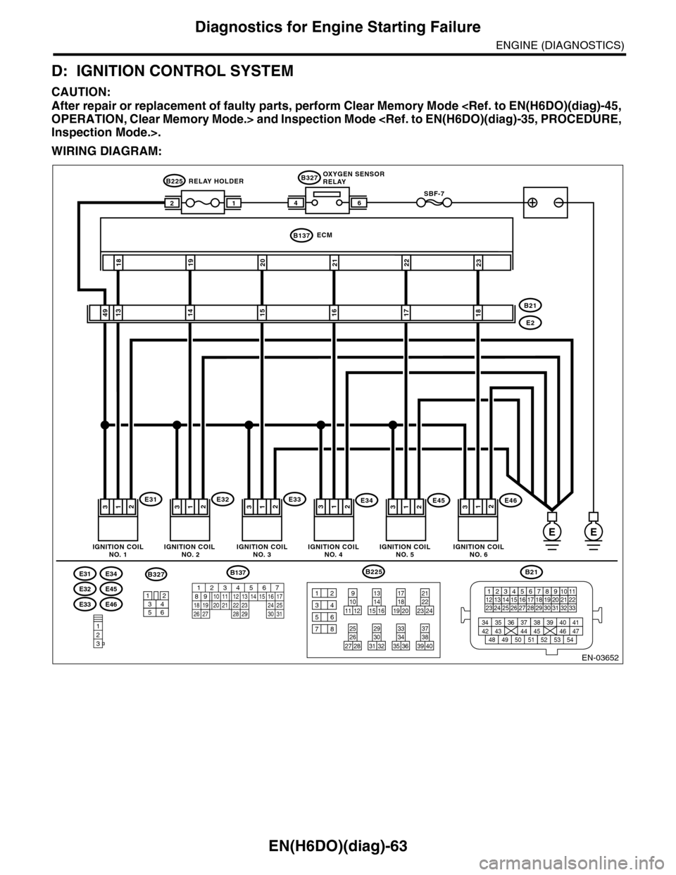
D: IGNITION CONTROL SYSTEM
CAUTION:
After repair or replacement of faulty parts, perform Clear Memory Mode
WIRING DIAGRAM:
EN-03652
E34
E45
E31
E32
E46E33
123
ECMB137
231918212220
SBF-746
B327
E46
E2
B21
E32
1814131617
32312E3432E4532
1549
111E31312E33312
12
B225
B21
123412131415567816171819910 1120212223 24 25 2627 28 29 3031 32 33
3534 37363938 41404342 4445 47464948 51505352 54
91012
34
56
78
11 121415 16
131819 20
172223 24
21
3839 40
373435 36
333031 32
292627 28
25
B225B327
3412
56
EE
OXYGEN SENSORRELAY
IGNITION COILNO. 1
RELAY HOLDER
IGNITION COIL NO. 2IGNITION COILNO. 3IGNITION COILNO. 4IGNITION COILNO. 5IGNITION COILNO. 6
B137
85610 11 12 13 14 157213416
3019 20 2228 29
91718 2521 23 243126 27
Page 1247 of 2453
EN(H6DO)(diag)-86
Diagnostic Procedure with Diagnostic Trouble Code (DTC)
ENGINE (DIAGNOSTICS)
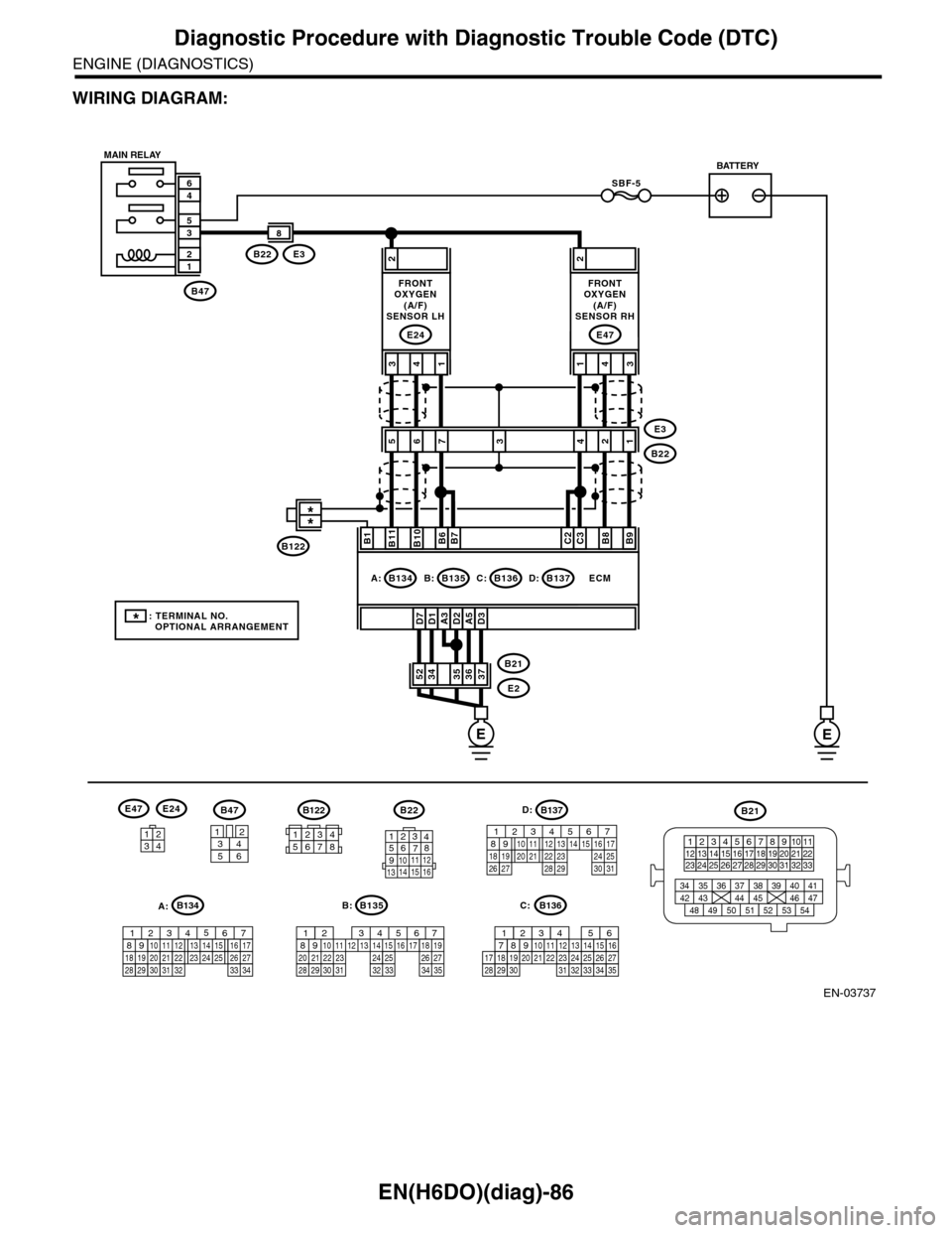
WIRING DIAGRAM:
EN-03737
SBF-5
B47
12
35
46
A3D1D7D2A5D3
2
3736353452B21
E2
ECM
B11B1B10B6B7C2C3B8B9
413
E24
2
431
E47
E3B22
8
56E3
B222134
B47
3456
12
B22
1234567891011 121314 15 16
3412
E47E24
B135
567821943102422 23 2511 12 13 14 1526 2728
16 17 18 1920 2129 30 31 32 33 34 35
B:
B21
123412131415567816171819910 1120212223 24 25 2627 28 29 3031 32 33
3534 37363938 41404342 4445 47464948 51505352 54
EE
B135B:B136C:B137D:B134A:
7
FRONTOXYGEN(A/F)SENSOR LH
FRONTOXYGEN(A/F)SENSOR RH
MAIN RELAYBATTERY
B136
16101112131415252430
9871718192028212223293231
123456
2726333435
C:
B137
85610 11 12 13 14 157213416
3019 20 2228 29
91718 2521 23 243126 27
D:B122
34561278
*: TERMINAL NO. OPTIONAL ARRANGEMENT
**
B122
A:B134
85610 11 12 13 14 157213416
3019 20 2228 29
91718252123 24323126 2733 34
Page 1250 of 2453
EN(H6DO)(diag)-89
Diagnostic Procedure with Diagnostic Trouble Code (DTC)
ENGINE (DIAGNOSTICS)
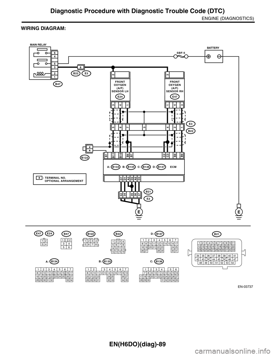
WIRING DIAGRAM:
EN-03737
SBF-5
B47
12
35
46
A3D1D7D2A5D3
2
3736353452B21
E2
ECM
B11B1B10B6B7C2C3B8B9
413
E24
2
431
E47
E3B22
8
56E3
B222134
B47
3456
12
B22
1234567891011 121314 15 16
3412
E47E24
B135
567821943102422 23 2511 12 13 14 1526 2728
16 17 18 1920 2129 30 31 32 33 34 35
B:
B21
123412131415567816171819910 1120212223 24 25 2627 28 29 3031 32 33
3534 37363938 41404342 4445 47464948 51505352 54
EE
B135B:B136C:B137D:B134A:
7
FRONTOXYGEN(A/F)SENSOR LH
FRONTOXYGEN(A/F)SENSOR RH
MAIN RELAYBATTERY
B136
16101112131415252430
9871718192028212223293231
123456
2726333435
C:
B137
85610 11 12 13 14 157213416
3019 20 2228 29
91718 2521 23 243126 27
D:B122
34561278
*: TERMINAL NO. OPTIONAL ARRANGEMENT
**
B122
A:B134
85610 11 12 13 14 157213416
3019 20 2228 29
91718252123 24323126 2733 34