2009 SUBARU TRIBECA Oil pump
[x] Cancel search: Oil pumpPage 1196 of 2453
EN(H6DO)(diag)-35
Inspection Mode
ENGINE (DIAGNOSTICS)
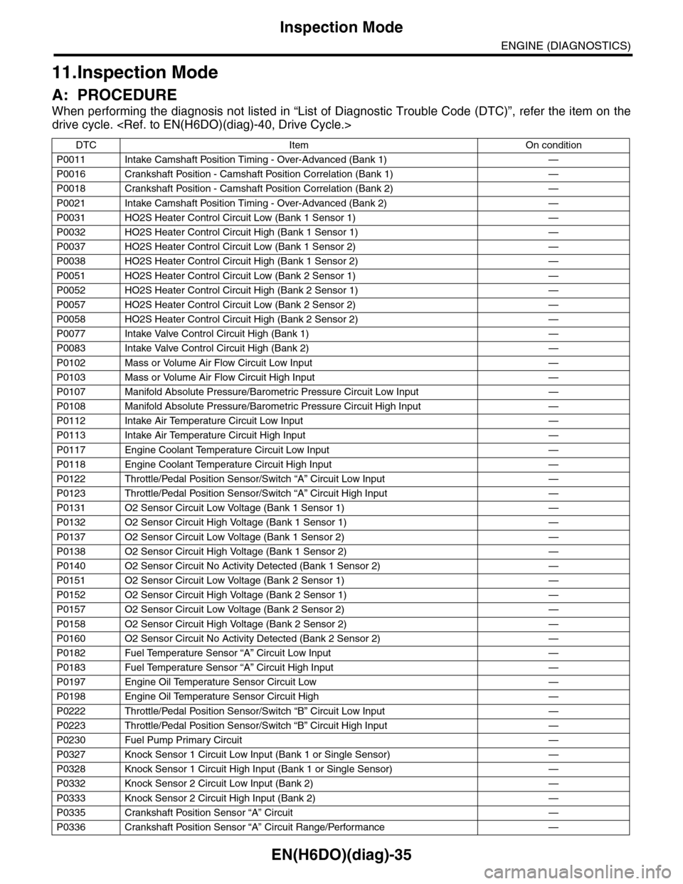
11.Inspection Mode
A: PROCEDURE
When performing the diagnosis not listed in “List of Diagnostic Trouble Code (DTC)”, refer the item on the
drive cycle.
DTC Item On condition
P0011 Intake Camshaft Position Timing - Over-Advanced (Bank 1) —
P0016 Crankshaft Position - Camshaft Position Correlation (Bank 1) —
P0018 Crankshaft Position - Camshaft Position Correlation (Bank 2) —
P0021 Intake Camshaft Position Timing - Over-Advanced (Bank 2) —
P0031 HO2S Heater Control Circuit Low (Bank 1 Sensor 1) —
P0032 HO2S Heater Control Circuit High (Bank 1 Sensor 1) —
P0037 HO2S Heater Control Circuit Low (Bank 1 Sensor 2) —
P0038 HO2S Heater Control Circuit High (Bank 1 Sensor 2) —
P0051 HO2S Heater Control Circuit Low (Bank 2 Sensor 1) —
P0052 HO2S Heater Control Circuit High (Bank 2 Sensor 1) —
P0057 HO2S Heater Control Circuit Low (Bank 2 Sensor 2) —
P0058 HO2S Heater Control Circuit High (Bank 2 Sensor 2) —
P0077 Intake Valve Control Circuit High (Bank 1) —
P0083 Intake Valve Control Circuit High (Bank 2) —
P0102 Mass or Volume Air Flow Circuit Low Input —
P0103 Mass or Volume Air Flow Circuit High Input —
P0107 Manifold Absolute Pressure/Barometric Pressure Circuit Low Input —
P0108 Manifold Absolute Pressure/Barometric Pressure Circuit High Input —
P0112 Intake Air Temperature Circuit Low Input —
P0113 Intake Air Temperature Circuit High Input —
P0117 Engine Coolant Temperature Circuit Low Input —
P0118 Engine Coolant Temperature Circuit High Input —
P0122 Throttle/Pedal Position Sensor/Switch “A” Circuit Low Input —
P0123 Throttle/Pedal Position Sensor/Switch “A” Circuit High Input —
P0131 O2 Sensor Circuit Low Voltage (Bank 1 Sensor 1) —
P0132 O2 Sensor Circuit High Voltage (Bank 1 Sensor 1) —
P0137 O2 Sensor Circuit Low Voltage (Bank 1 Sensor 2) —
P0138 O2 Sensor Circuit High Voltage (Bank 1 Sensor 2) —
P0140 O2 Sensor Circuit No Activity Detected (Bank 1 Sensor 2) —
P0151 O2 Sensor Circuit Low Voltage (Bank 2 Sensor 1) —
P0152 O2 Sensor Circuit High Voltage (Bank 2 Sensor 1) —
P0157 O2 Sensor Circuit Low Voltage (Bank 2 Sensor 2) —
P0158 O2 Sensor Circuit High Voltage (Bank 2 Sensor 2) —
P0160 O2 Sensor Circuit No Activity Detected (Bank 2 Sensor 2) —
P0182 Fuel Temperature Sensor “A” Circuit Low Input —
P0183 Fuel Temperature Sensor “A” Circuit High Input —
P0197 Engine Oil Temperature Sensor Circuit Low —
P0198 Engine Oil Temperature Sensor Circuit High —
P0222 Throttle/Pedal Position Sensor/Switch “B” Circuit Low Input —
P0223 Throttle/Pedal Position Sensor/Switch “B” Circuit High Input —
P0230 Fuel Pump Primary Circuit —
P0327 Knock Sensor 1 Circuit Low Input (Bank 1 or Single Sensor) —
P0328 Knock Sensor 1 Circuit High Input (Bank 1 or Single Sensor) —
P0332 Knock Sensor 2 Circuit Low Input (Bank 2) —
P0333 Knock Sensor 2 Circuit High Input (Bank 2) —
P0335 Crankshaft Position Sensor “A” Circuit —
P0336 Crankshaft Position Sensor “A” Circuit Range/Performance —
Page 1225 of 2453
EN(H6DO)(diag)-64
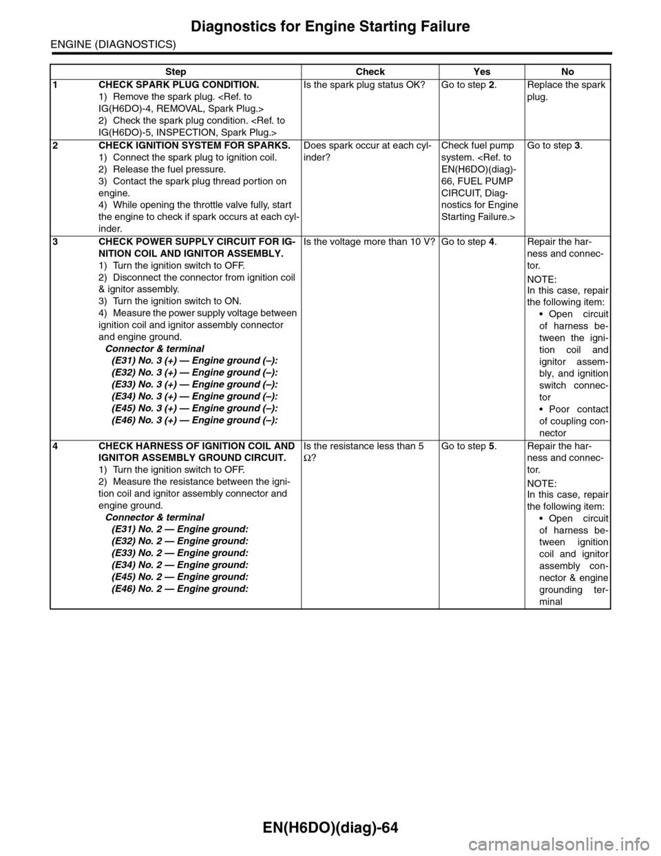
Diagnostics for Engine Starting Failure
ENGINE (DIAGNOSTICS)
Step Check Yes No
1CHECK SPARK PLUG CONDITION.
1) Remove the spark plug.
2) Check the spark plug condition.
Is the spark plug status OK? Go to step 2.Replace the spark
plug.
2CHECK IGNITION SYSTEM FOR SPARKS.
1) Connect the spark plug to ignition coil.
2) Release the fuel pressure.
3) Contact the spark plug thread portion on
engine.
4) While opening the throttle valve fully, start
the engine to check if spark occurs at each cyl-
inder.
Does spark occur at each cyl-
inder?
Check fuel pump
system.
66, FUEL PUMP
CIRCUIT, Diag-
nostics for Engine
Starting Failure.>
Go to step 3.
3CHECK POWER SUPPLY CIRCUIT FOR IG-
NITION COIL AND IGNITOR ASSEMBLY.
1) Turn the ignition switch to OFF.
2) Disconnect the connector from ignition coil
& ignitor assembly.
3) Turn the ignition switch to ON.
4) Measure the power supply voltage between
ignition coil and ignitor assembly connector
and engine ground.
Connector & terminal
(E31) No. 3 (+) — Engine ground (–):
(E32) No. 3 (+) — Engine ground (–):
(E33) No. 3 (+) — Engine ground (–):
(E34) No. 3 (+) — Engine ground (–):
(E45) No. 3 (+) — Engine ground (–):
(E46) No. 3 (+) — Engine ground (–):
Is the voltage more than 10 V? Go to step 4.Repair the har-
ness and connec-
tor.
NOTE:
In this case, repair
the following item:
•Open circuit
of harness be-
tween the igni-
tion coil and
ignitor assem-
bly, and ignition
switch connec-
tor
•Poor contact
of coupling con-
nector
4CHECK HARNESS OF IGNITION COIL AND
IGNITOR ASSEMBLY GROUND CIRCUIT.
1) Turn the ignition switch to OFF.
2) Measure the resistance between the igni-
tion coil and ignitor assembly connector and
engine ground.
Connector & terminal
(E31) No. 2 — Engine ground:
(E32) No. 2 — Engine ground:
(E33) No. 2 — Engine ground:
(E34) No. 2 — Engine ground:
(E45) No. 2 — Engine ground:
(E46) No. 2 — Engine ground:
Is the resistance less than 5
Ω?
Go to step 5.Repair the har-
ness and connec-
tor.
NOTE:
In this case, repair
the following item:
•Open circuit
of harness be-
tween ignition
coil and ignitor
assembly con-
nector & engine
grounding ter-
minal
Page 1226 of 2453
EN(H6DO)(diag)-65
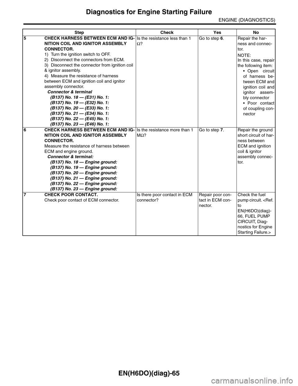
Diagnostics for Engine Starting Failure
ENGINE (DIAGNOSTICS)
5CHECK HARNESS BETWEEN ECM AND IG-
NITION COIL AND IGNITOR ASSEMBLY
CONNECTOR.
1) Turn the ignition switch to OFF.
2) Disconnect the connectors from ECM.
3) Disconnect the connector from ignition coil
& ignitor assembly.
4) Measure the resistance of harness
between ECM and ignition coil and ignitor
assembly connector.
Connector & terminal
(B137) No. 18 — (E31) No. 1:
(B137) No. 19 — (E32) No. 1:
(B137) No. 20 — (E33) No. 1:
(B137) No. 21 — (E34) No. 1:
(B137) No. 22 — (E45) No. 1:
(B137) No. 23 — (E46) No. 1:
Is the resistance less than 1
Ω?
Go to step 6.Repair the har-
ness and connec-
tor.
NOTE:In this case, repair
the following item:
•Open circuit
of harness be-
tween ECM and
ignition coil and
ignitor assem-
bly connector
•Poor contact
of coupling con-
nector
6CHECK HARNESS BETWEEN ECM AND IG-
NITION COIL AND IGNITOR ASSEMBLY
CONNECTOR.
Measure the resistance of harness between
ECM and engine ground.
Connector & terminal:
(B137) No. 18 — Engine ground:
(B137) No. 19 — Engine ground:
(B137) No. 20 — Engine ground:
(B137) No. 21 — Engine ground:
(B137) No. 22 — Engine ground:
(B137) No. 23 — Engine ground:
Is the resistance more than 1
MΩ?
Go to step 7.Repair the ground
short circuit of har-
ness between
ECM and ignition
coil & ignitor
assembly connec-
tor.
7CHECK POOR CONTACT.
Check poor contact of ECM connector.
Is there poor contact in ECM
connector?
Repair poor con-
tact in ECM con-
nector.
Check the fuel
pump circuit.
EN(H6DO)(diag)-
66, FUEL PUMP
CIRCUIT, Diag-
nostics for Engine
Starting Failure.>
Step Check Yes No
Page 1233 of 2453
EN(H6DO)(diag)-72
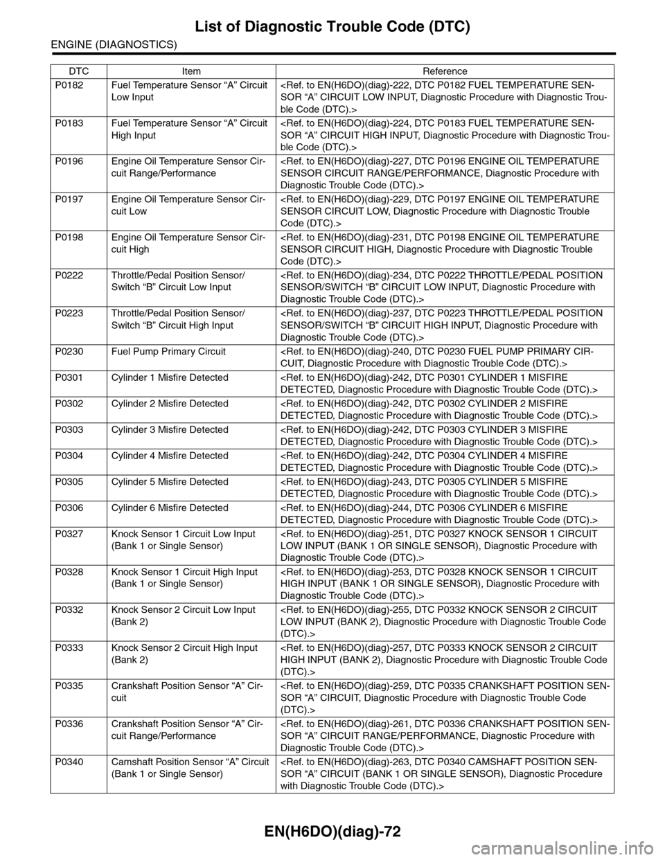
List of Diagnostic Trouble Code (DTC)
ENGINE (DIAGNOSTICS)
P0182 Fuel Temperature Sensor “A” Circuit
Low Input
ble Code (DTC).>
P0183 Fuel Temperature Sensor “A” Circuit
High Input
ble Code (DTC).>
P0196 Engine Oil Temperature Sensor Cir-
cuit Range/Performance
Diagnostic Trouble Code (DTC).>
P0197 Engine Oil Temperature Sensor Cir-
cuit Low
Code (DTC).>
P0198 Engine Oil Temperature Sensor Cir-
cuit High
Code (DTC).>
P0222 Throttle/Pedal Position Sensor/
Switch “B” Circuit Low Input
Diagnostic Trouble Code (DTC).>
P0223 Throttle/Pedal Position Sensor/
Switch “B” Circuit High Input
Diagnostic Trouble Code (DTC).>
P0230 Fuel Pump Primary Circuit
P0301 Cylinder 1 Misfire Detected
P0302 Cylinder 2 Misfire Detected
P0303 Cylinder 3 Misfire Detected
P0304 Cylinder 4 Misfire Detected
P0305 Cylinder 5 Misfire Detected
P0306 Cylinder 6 Misfire Detected
P0327 Knock Sensor 1 Circuit Low Input
(Bank 1 or Single Sensor)
Diagnostic Trouble Code (DTC).>
P0328 Knock Sensor 1 Circuit High Input
(Bank 1 or Single Sensor)
Diagnostic Trouble Code (DTC).>
P0332 Knock Sensor 2 Circuit Low Input
(Bank 2)
(DTC).>
P0333 Knock Sensor 2 Circuit High Input
(Bank 2)
(DTC).>
P0335 Crankshaft Position Sensor “A” Cir-
cuit
(DTC).>
P0336 Crankshaft Position Sensor “A” Cir-
cuit Range/Performance
Diagnostic Trouble Code (DTC).>
P0340 Camshaft Position Sensor “A” Circuit
(Bank 1 or Single Sensor)
with Diagnostic Trouble Code (DTC).>
DTC Item Reference
Page 1553 of 2453
EN(H6DO)(diag)-392
General Diagnostic Table
ENGINE (DIAGNOSTICS)
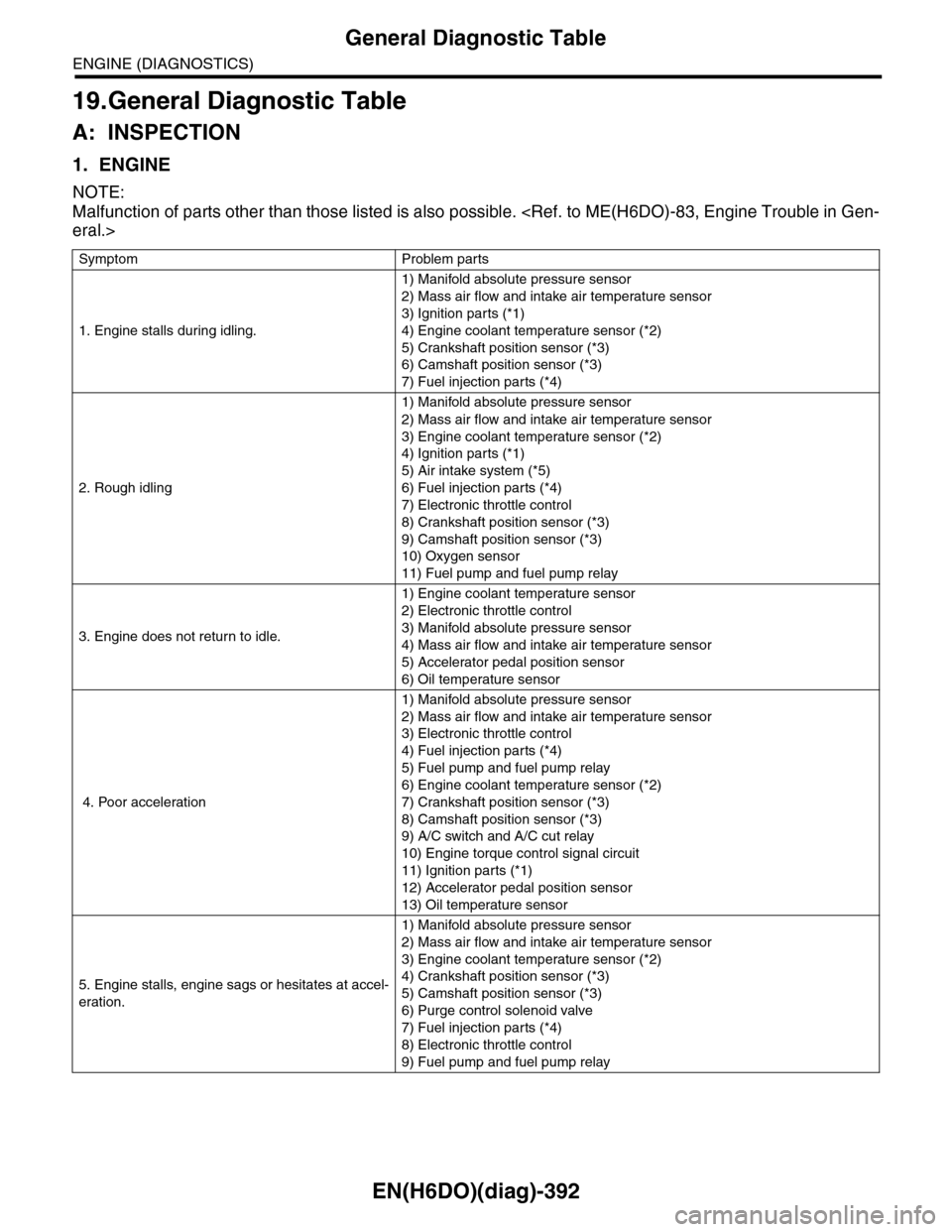
19.General Diagnostic Table
A: INSPECTION
1. ENGINE
NOTE:
Malfunction of parts other than those listed is also possible.
Symptom Problem parts
1. Engine stalls during idling.
1) Manifold absolute pressure sensor
2) Mass air flow and intake air temperature sensor
3) Ignition parts (*1)
4) Engine coolant temperature sensor (*2)
5) Crankshaft position sensor (*3)
6) Camshaft position sensor (*3)
7) Fuel injection parts (*4)
2. Rough idling
1) Manifold absolute pressure sensor
2) Mass air flow and intake air temperature sensor
3) Engine coolant temperature sensor (*2)
4) Ignition parts (*1)
5) Air intake system (*5)
6) Fuel injection parts (*4)
7) Electronic throttle control
8) Crankshaft position sensor (*3)
9) Camshaft position sensor (*3)
10) Oxygen sensor
11) Fuel pump and fuel pump relay
3. Engine does not return to idle.
1) Engine coolant temperature sensor
2) Electronic throttle control
3) Manifold absolute pressure sensor
4) Mass air flow and intake air temperature sensor
5) Accelerator pedal position sensor
6) Oil temperature sensor
4. Poor acceleration
1) Manifold absolute pressure sensor
2) Mass air flow and intake air temperature sensor
3) Electronic throttle control
4) Fuel injection parts (*4)
5) Fuel pump and fuel pump relay
6) Engine coolant temperature sensor (*2)
7) Crankshaft position sensor (*3)
8) Camshaft position sensor (*3)
9) A/C switch and A/C cut relay
10) Engine torque control signal circuit
11) Ignition parts (*1)
12) Accelerator pedal position sensor
13) Oil temperature sensor
5. Engine stalls, engine sags or hesitates at accel-
eration.
1) Manifold absolute pressure sensor
2) Mass air flow and intake air temperature sensor
3) Engine coolant temperature sensor (*2)
4) Crankshaft position sensor (*3)
5) Camshaft position sensor (*3)
6) Purge control solenoid valve
7) Fuel injection parts (*4)
8) Electronic throttle control
9) Fuel pump and fuel pump relay
Page 1554 of 2453
EN(H6DO)(diag)-393
General Diagnostic Table
ENGINE (DIAGNOSTICS)
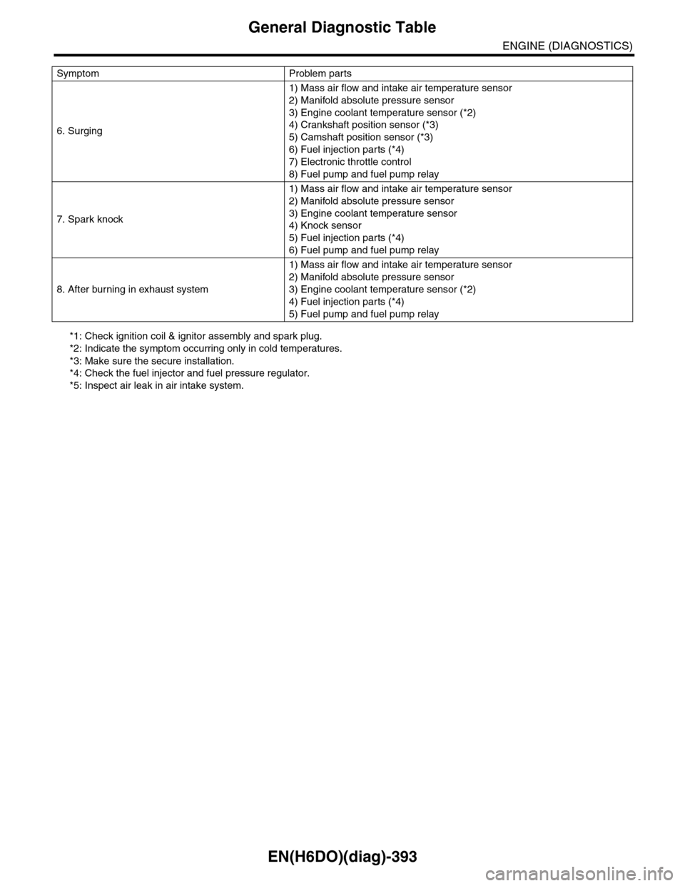
*1: Check ignition coil & ignitor assembly and spark plug.
*2: Indicate the symptom occurring only in cold temperatures.
*3: Make sure the secure installation.
*4: Check the fuel injector and fuel pressure regulator.
*5: Inspect air leak in air intake system.
6. Surging
1) Mass air flow and intake air temperature sensor
2) Manifold absolute pressure sensor
3) Engine coolant temperature sensor (*2)
4) Crankshaft position sensor (*3)
5) Camshaft position sensor (*3)
6) Fuel injection parts (*4)
7) Electronic throttle control
8) Fuel pump and fuel pump relay
7. Spark knock
1) Mass air flow and intake air temperature sensor
2) Manifold absolute pressure sensor
3) Engine coolant temperature sensor
4) Knock sensor
5) Fuel injection parts (*4)
6) Fuel pump and fuel pump relay
8. After burning in exhaust system
1) Mass air flow and intake air temperature sensor
2) Manifold absolute pressure sensor
3) Engine coolant temperature sensor (*2)
4) Fuel injection parts (*4)
5) Fuel pump and fuel pump relay
Symptom Problem parts
Page 1616 of 2453
GD(H6DO)-4
List of Diagnostic Trouble Code (DTC)
GENERAL DESCRIPTION
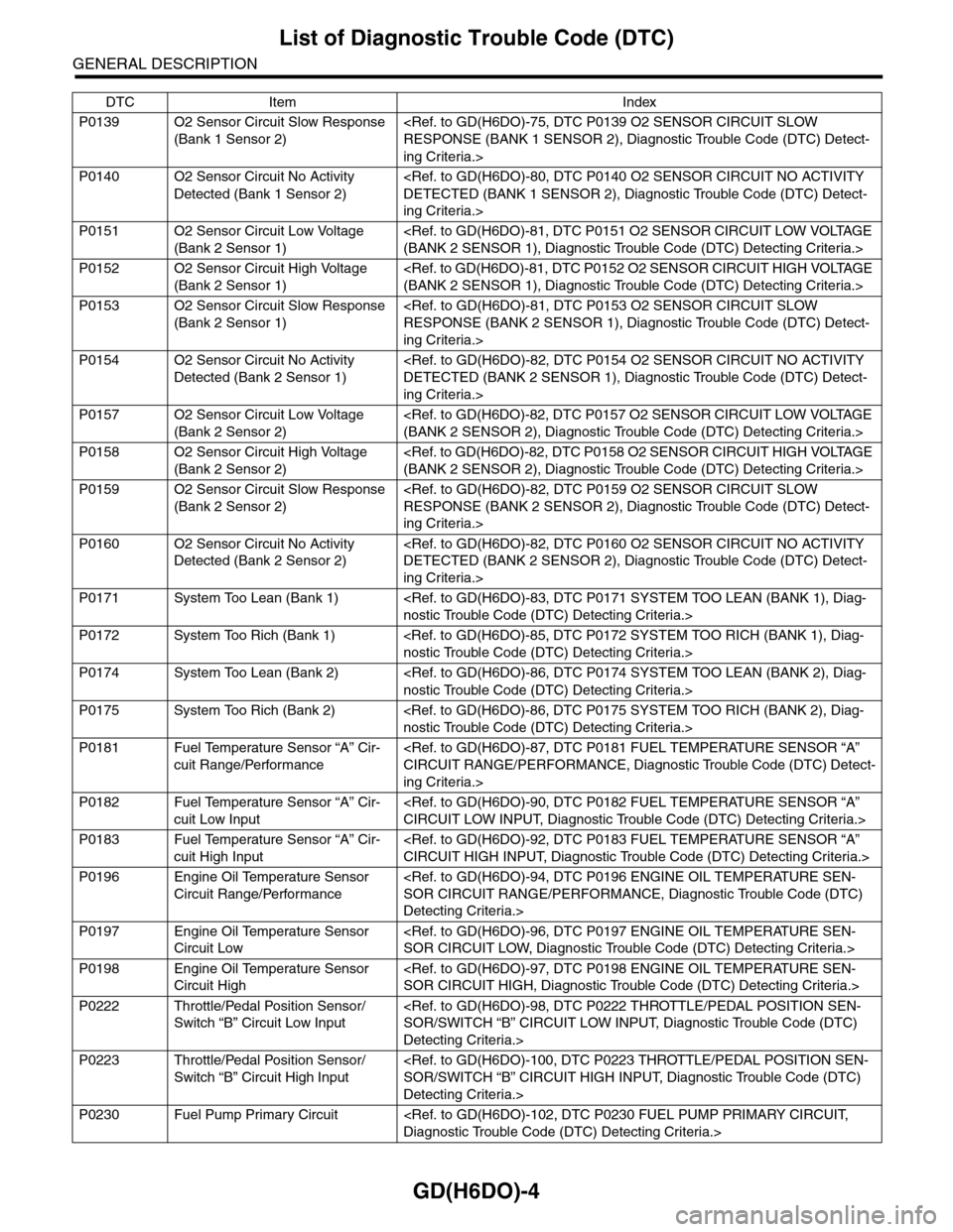
P0139 O2 Sensor Circuit Slow Response
(Bank 1 Sensor 2)
ing Criteria.>
P0140 O2 Sensor Circuit No Activity
Detected (Bank 1 Sensor 2)
ing Criteria.>
P0151 O2 Sensor Circuit Low Voltage
(Bank 2 Sensor 1)
P0152 O2 Sensor Circuit High Voltage
(Bank 2 Sensor 1)
P0153 O2 Sensor Circuit Slow Response
(Bank 2 Sensor 1)
ing Criteria.>
P0154 O2 Sensor Circuit No Activity
Detected (Bank 2 Sensor 1)
ing Criteria.>
P0157 O2 Sensor Circuit Low Voltage
(Bank 2 Sensor 2)
P0158 O2 Sensor Circuit High Voltage
(Bank 2 Sensor 2)
P0159 O2 Sensor Circuit Slow Response
(Bank 2 Sensor 2)
ing Criteria.>
P0160 O2 Sensor Circuit No Activity
Detected (Bank 2 Sensor 2)
ing Criteria.>
P0171 System Too Lean (Bank 1)
P0172 System Too Rich (Bank 1)
P0174 System Too Lean (Bank 2)
P0175 System Too Rich (Bank 2)
P0181 Fuel Temperature Sensor “A” Cir-
cuit Range/Performance
ing Criteria.>
P0182 Fuel Temperature Sensor “A” Cir-
cuit Low Input
P0183 Fuel Temperature Sensor “A” Cir-
cuit High Input
P0196 Engine Oil Temperature Sensor
Circuit Range/Performance
Detecting Criteria.>
P0197 Engine Oil Temperature Sensor
Circuit Low
P0198 Engine Oil Temperature Sensor
Circuit High
P0222 Throttle/Pedal Position Sensor/
Switch “B” Circuit Low Input
Detecting Criteria.>
P0223 Throttle/Pedal Position Sensor/
Switch “B” Circuit High Input
Detecting Criteria.>
P0230 Fuel Pump Primary Circuit
DTC Item Index
Page 1851 of 2453
LU(H6DO)-2
General Description
LUBRICATION
1. General Description
A: SPECIFICATION
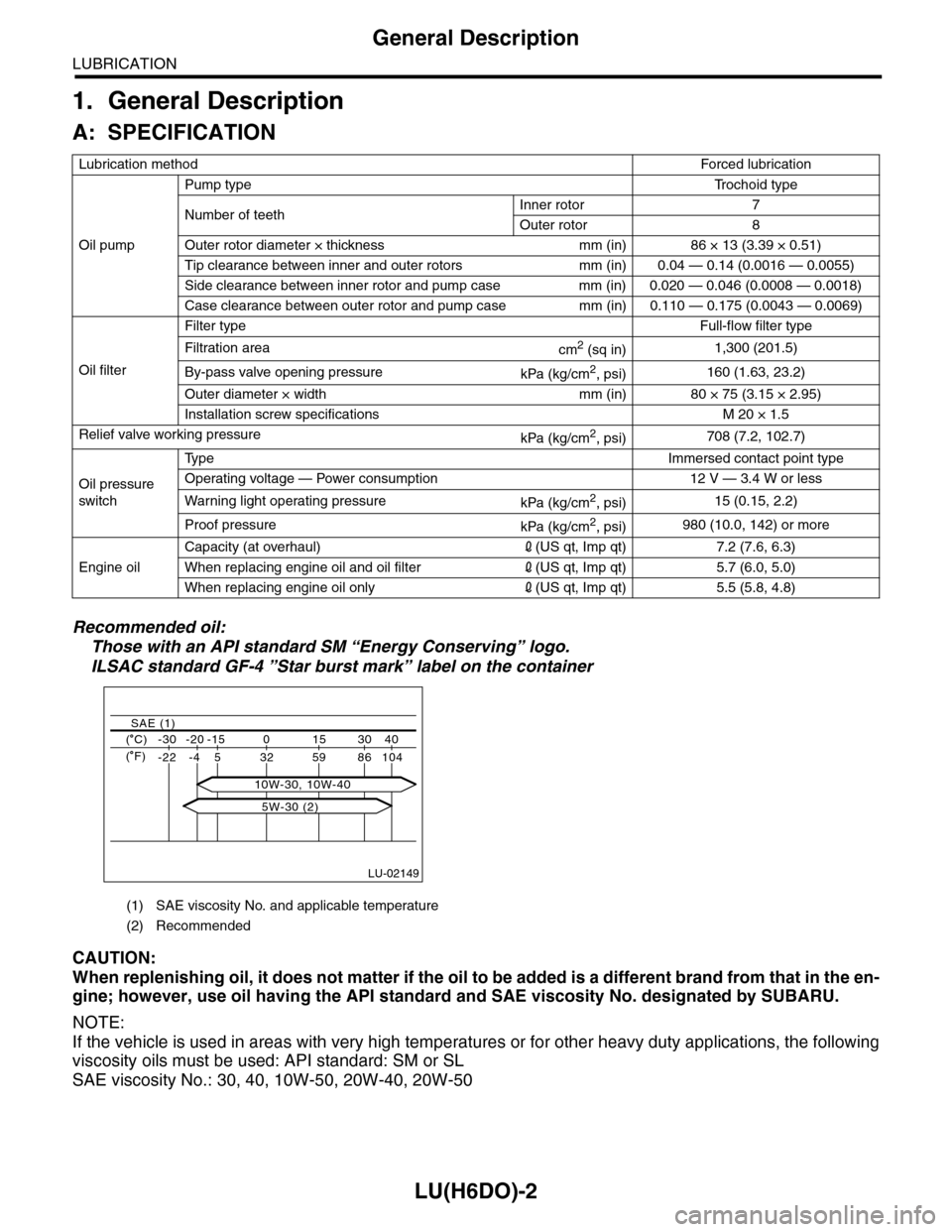
Recommended oil:
Those with an API standard SM “Energy Conserving” logo.
ILSAC standard GF-4 ”Star burst mark” label on the container
CAUTION:
When replenishing oil, it does not matter if the oil to be added is a different brand from that in the en-
gine; however, use oil having the API standard and SAE viscosity No. designated by SUBARU.
NOTE:
If the vehicle is used in areas with very high temperatures or for other heavy duty applications, the following
viscosity oils must be used: API standard: SM or SL
SAE viscosity No.: 30, 40, 10W-50, 20W-40, 20W-50
Lubrication methodForced lubr ication
Oil pump
Pump typeTr o c h o i d t y p e
Number of teethInner rotor 7
Outer rotor 8
Outer rotor diameter × thickness mm (in) 86 × 13 (3.39 × 0.51)
Tip clearance between inner and outer rotors mm (in) 0.04 — 0.14 (0.0016 — 0.0055)
Side clearance between inner rotor and pump case mm (in) 0.020 — 0.046 (0.0008 — 0.0018)
Case clearance between outer rotor and pump case mm (in) 0.110 — 0.175 (0.0043 — 0.0069)
Oil filter
Filter typeFull-flow filter type
Filtration areacm2 (sq in)1,300 (201.5)
By-pass valve opening pressurekPa (kg/cm2, psi)160 (1.63, 23.2)
Outer diameter × width mm (in) 80 × 75 (3.15 × 2.95)
Installation screw specifications M 20 × 1.5
Relief valve working pressurekPa (kg/cm2, psi)708 (7.2, 102.7)
Oil pressure
switch
Ty p eImmersed contact point type
Operating voltage — Power consumption 12 V — 3.4 W or less
Wa r ni n g l ig h t o p era t i ng pr e ss ur ekPa (kg/cm2, psi)15 (0.15, 2.2)
Proof pressurekPa (kg/cm2, psi)980 (10.0, 142) or more
Engine oil
Capacity (at overhaul)2(US qt, Imp qt) 7.2 (7.6, 6.3)
When replacing engine oil and oil filter2(US qt, Imp qt) 5.7 (6.0, 5.0)
When replacing engine oil only2(US qt, Imp qt) 5.5 (5.8, 4.8)
(1) SAE viscosity No. and applicable temperature
(2) Recommended
LU-02149
( C) -30 -20 -15 0 15 30 40
-22 -4 5 32 59 86 104
SAE (1)
( F)
5W-30 (2)
10W-30, 10W-40