Page 2033 of 2453
5AT-17
General Description
AUTOMATIC TRANSMISSION
C: CAUTION
•Wear work clothing, including a cap, protective goggles and protective shoes during operation.
•Remove contamination including dirt and corrosion before removal, installation or disassembly.
•Keep the disassembled parts in order and protect them from dust and dirt.
•Until the oil pan is removed, do not place with the oil pan side facing up to prevent foreign matter from en-
tering the valve body.
•Before removal, installation or disassembly, be sure to clarify the failure. Avoid unnecessary removal, dis-
assembly and replacement.
•When disassembling the case and other light alloy parts, disassemble them by slightly tapping with a plas-
tic hammer. Do not pry apart with screwdrivers or other tools.
•Be careful not to burn yourself, because each part on the vehicle is hot after running.
•Use SUBARU genuine gear oil, grease or the equivalent. Do not mix them with that of another grade or
from other manufacturers.
•Be sure to tighten bolts and nuts to the specified torque.
•Place shop jacks or rigid racks at the specified points.
•Apply gear oil onto sliding or revolution surfaces before installation.
•Replace deformed or damaged snap rings with new parts.
•Before installing O-rings or oil seals, apply sufficient amount of ATF fluid to avoid damage and deforma-
tion.
•Be careful not to incorrectly install or fail to install O-rings, snap rings and other such parts.
•Before securing a part on a vise, place cushioning material such as wood blocks, aluminum plate, or cloth
between the part and the vise.
•Avoid damaging the mating surface of the case.
•Before applying liquid gasket, completely remove the old seal.
D: PREPARATION TOOL
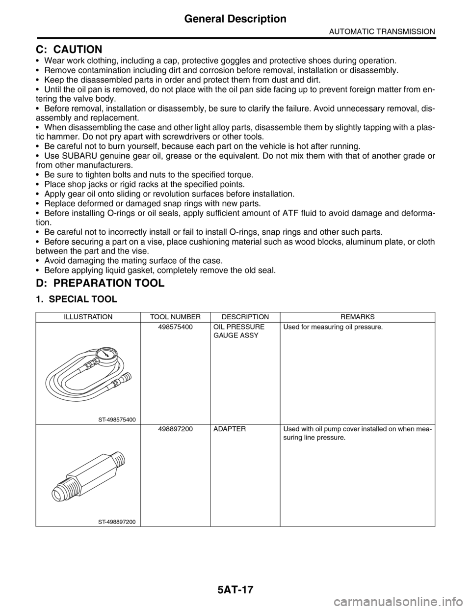
1. SPECIAL TOOL
ILLUSTRATION TOOL NUMBER DESCRIPTION REMARKS
498575400 OIL PRESSURE
GAUGE ASSY
Used for measuring oil pressure.
498897200 ADAPTER Used with oil pump cover installed on when mea-
suring line pressure.
ST-498575400
ST-498897200
Page 2041 of 2453
5AT-25
General Description
AUTOMATIC TRANSMISSION
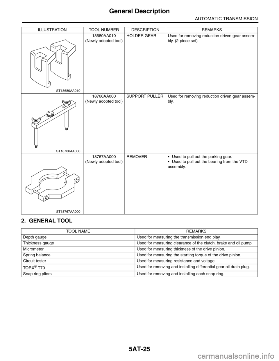
2. GENERAL TOOL
18680AA010
(Newly adopted tool)
HOLDER GEAR Used for removing reduction driven gear assem-
bly. (2-piece set)
18766AA000
(Newly adopted tool)
SUPPORT PULLER Used for removing reduction driven gear assem-
bly.
18767AA000
(Newly adopted tool)
REMOVER • Used to pull out the parking gear.
•Used to pull out the bearing from the VTD
assembly.
TO OL N AM E RE MA R KS
Depth gauge Used for measuring the transmission end play.
Thickness gauge Used for measuring clearance of the clutch, brake and oil pump.
Micrometer Used for measuring thickness of the drive pinion.
Spring balance Used for measuring the starting torque of the drive pinion.
Circuit tester Used for measuring resistance and voltage.
TO RX® T70Used for removing and installing differential gear oil drain plug.
Snap ring pliers Used for removing and installing each snap ring.
ILLUSTRATION TOOL NUMBER DESCRIPTION REMARKS
ST18680AA010
ST18766AA000
ST18767AA000
Page 2055 of 2453
5AT-39
Automatic Transmission Assembly
AUTOMATIC TRANSMISSION
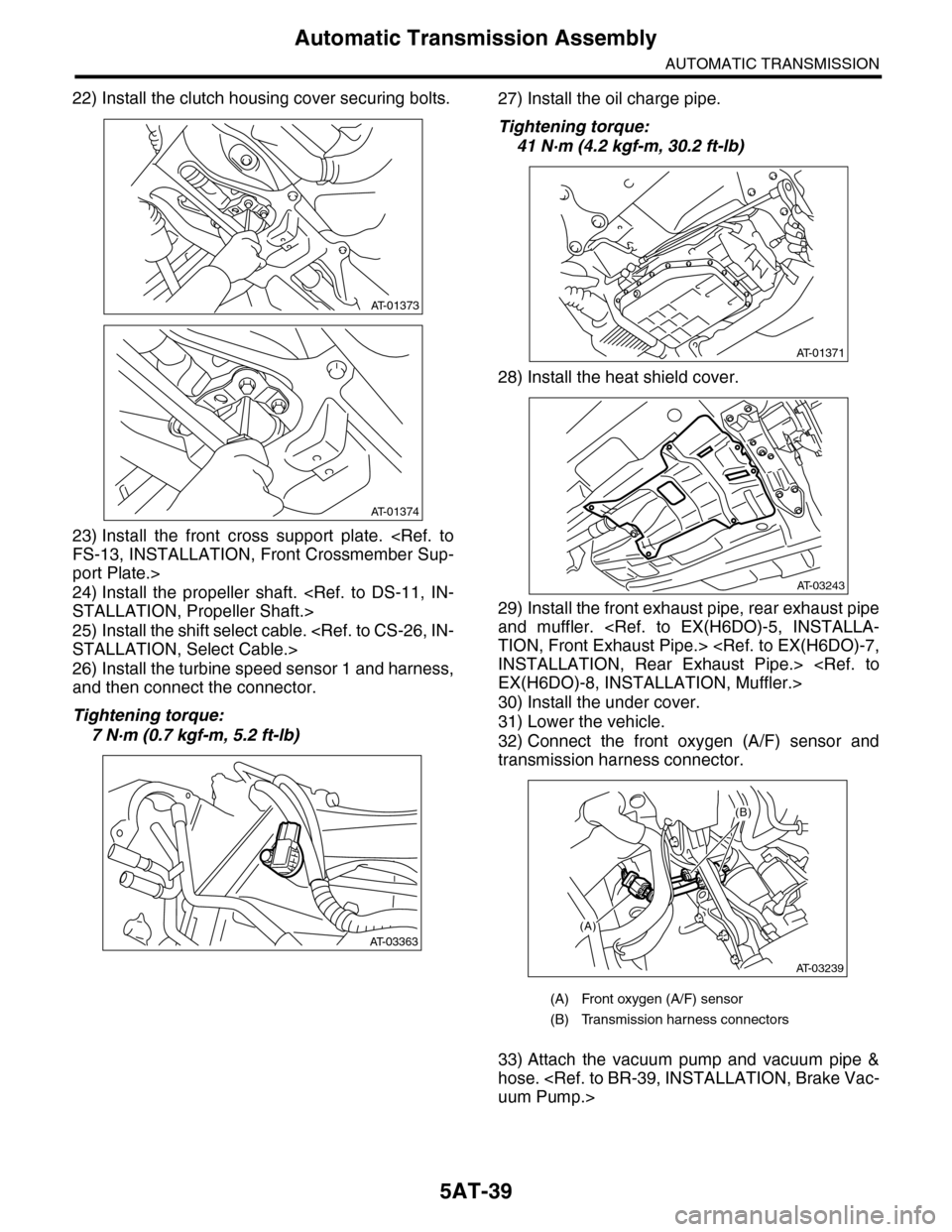
22) Install the clutch housing cover securing bolts.
23) Install the front cross support plate.
FS-13, INSTALLATION, Front Crossmember Sup-
port Plate.>
24) Install the propeller shaft.
STALLATION, Propeller Shaft.>
25) Install the shift select cable.
STALLATION, Select Cable.>
26) Install the turbine speed sensor 1 and harness,
and then connect the connector.
Tightening torque:
7 N·m (0.7 kgf-m, 5.2 ft-lb)
27) Install the oil charge pipe.
Tightening torque:
41 N·m (4.2 kgf-m, 30.2 ft-lb)
28) Install the heat shield cover.
29) Install the front exhaust pipe, rear exhaust pipe
and muffler.
TION, Front Exhaust Pipe.>
INSTALLATION, Rear Exhaust Pipe.>
EX(H6DO)-8, INSTALLATION, Muffler.>
30) Install the under cover.
31) Lower the vehicle.
32) Connect the front oxygen (A/F) sensor and
transmission harness connector.
33) Attach the vacuum pump and vacuum pipe &
hose.
uum Pump.>
AT-01373
AT-01374
AT-03363
(A) Front oxygen (A/F) sensor
(B) Transmission harness connectors
AT-01371
AT-03243
(A)
(B)
AT-03239
Page 2078 of 2453
5AT-62
Torque Converter Assembly
AUTOMATIC TRANSMISSION
23.Torque Converter Assembly
A: REMOVAL
1) Remove the transmission assembly from vehicle
body.
Transmission Assembly.>
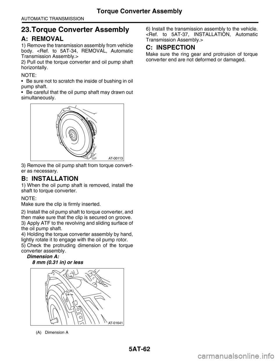
2) Pull out the torque converter and oil pump shaft
horizontally.
NOTE:
•Be sure not to scratch the inside of bushing in oil
pump shaft.
•Be careful that the oil pump shaft may drawn out
simultaneously.
3) Remove the oil pump shaft from torque convert-
er as necessary.
B: INSTALLATION
1) When the oil pump shaft is removed, install the
shaft to torque converter.
NOTE:
Make sure the clip is firmly inserted.
2) Install the oil pump shaft to torque converter, and
then make sure that the clip is secured on groove.
3) Apply ATF to the revolving and sliding surface of
the oil pump shaft.
4) Holding the torque converter assembly by hand,
lightly rotate it to engage with the oil pump rotor.
5) Check the protruding dimension of the torque
converter assembly.
Dimension A:
8 mm (0.31 in) or less
6) Install the transmission assembly to the vehicle.
Transmission Assembly.>
C: INSPECTION
Make sure the ring gear and protrusion of torque
converter end are not deformed or damaged.
(A) Dimension A
AT-00113
AT-01641
(A)
Page 2093 of 2453
5AT-77
Oil Pump Cover
AUTOMATIC TRANSMISSION
31.Oil Pump Cover
A: REMOVAL
1) Remove the transmission assembly from vehicle
body.
Transmission Assembly.>
2) Pull out the torque converter assembly.
5AT-62, REMOVAL, Torque Converter Assembly.>
3) Remove the transmission harness connector
from stay.
4) Remove the oil charge pipe.
REMOVAL, Oil Charge Pipe.>
5) Remove the ATF filter inlet and outlet pipes.
Hose.>
6) Separate the converter case and transmission
case.
Case.>
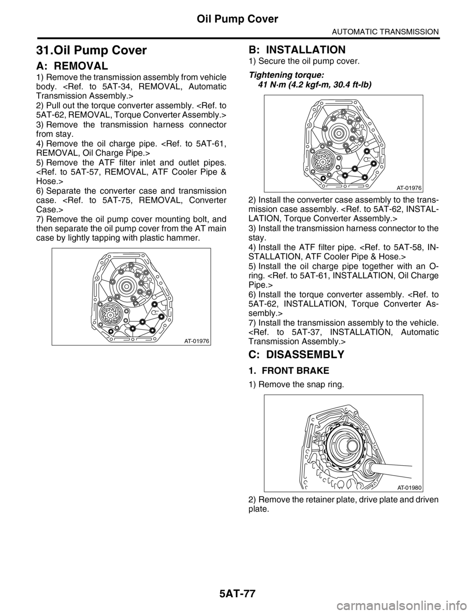
7) Remove the oil pump cover mounting bolt, and
then separate the oil pump cover from the AT main
case by lightly tapping with plastic hammer.
B: INSTALLATION
1) Secure the oil pump cover.
Tightening torque:
41 N·m (4.2 kgf-m, 30.4 ft-lb)
2) Install the converter case assembly to the trans-
mission case assembly.
LATION, Torque Converter Assembly.>
3) Install the transmission harness connector to the
stay.
4) Install the ATF filter pipe.
STALLATION, ATF Cooler Pipe & Hose.>
5) Install the oil charge pipe together with an O-
ring.
Pipe.>
6) Install the torque converter assembly.
5AT-62, INSTALLATION, Torque Converter As-
sembly.>
7) Install the transmission assembly to the vehicle.
Transmission Assembly.>
C: DISASSEMBLY
1. FRONT BRAKE
1) Remove the snap ring.
2) Remove the retainer plate, drive plate and driven
plate.
AT-01976
AT-01976
AT-01980
Page 2094 of 2453
5AT-78
Oil Pump Cover
AUTOMATIC TRANSMISSION
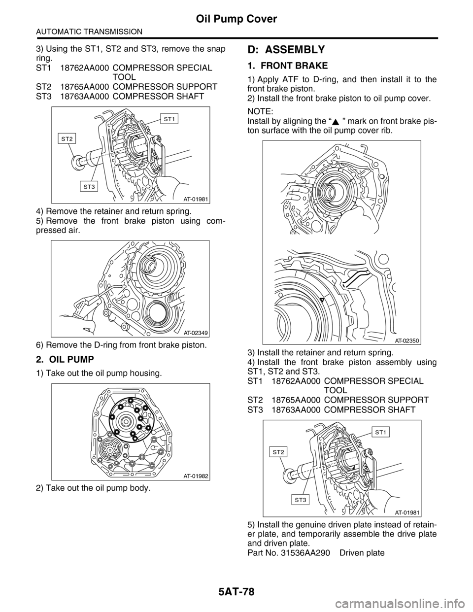
3) Using the ST1, ST2 and ST3, remove the snap
ring.
ST1 18762AA000 COMPRESSOR SPECIAL
TOOL
ST2 18765AA000 COMPRESSOR SUPPORT
ST3 18763AA000 COMPRESSOR SHAFT
4) Remove the retainer and return spring.
5) Remove the front brake piston using com-
pressed air.
6) Remove the D-ring from front brake piston.
2. OIL PUMP
1) Take out the oil pump housing.
2) Take out the oil pump body.
D: ASSEMBLY
1. FRONT BRAKE
1) Apply ATF to D-ring, and then install it to the
front brake piston.
2) Install the front brake piston to oil pump cover.
NOTE:
Install by aligning the “ ” mark on front brake pis-
ton surface with the oil pump cover rib.
3) Install the retainer and return spring.
4) Install the front brake piston assembly using
ST1, ST2 and ST3.
ST1 18762AA000 COMPRESSOR SPECIAL
TOOL
ST2 18765AA000 COMPRESSOR SUPPORT
ST3 18763AA000 COMPRESSOR SHAFT
5) Install the genuine driven plate instead of retain-
er plate, and temporarily assemble the drive plate
and driven plate.
Part No. 31536AA290 Driven plate
AT-01981
ST1
ST2
ST3
AT-02349
AT-01982
AT-02350
AT-01981
ST1
ST2
ST3
Page 2095 of 2453
5AT-79
Oil Pump Cover
AUTOMATIC TRANSMISSION
6) Install the snap ring.
7) Measure the clearance between retainer plate
and snap ring, and then select the suitable retainer
plate from table.
Front brake clearance specification:
0.7 — 1.1 mm (0.028 — 0.043 in)
8) Remove the snap ring, replace the driven plate
used in measurement of clearance with the retainer
plate, and then reassemble.
2. OIL PUMP
1) Apply ATF to oil pump assembly, and then install
it to oil pump housing.
2) Install the O-ring to oil pump cover.
3) Install the oil pump housing to the oil pump cov-
er.
Tightening torque:
10 N·m (1.0 kgf-m, 7.4 ft-lb)
Front brake retainer plate
Par t No. Thickness mm (in)
31567AB130 3.4 (0.134)
31567AB140 3.6 (0.142)
31567AB150 3.8 (0.150)
31567AB160 4.0 (0.157)
AT-01980
AT-01983
AT-01982
Page 2096 of 2453
5AT-80
Oil Pump Cover
AUTOMATIC TRANSMISSION
E: INSPECTION
1. FRONT BRAKE
Check the following items.
•Drive plate facing for wear and damage
•Snap ring for wear, return spring for damage,
and retainer for damage
•Piston for damage
•D-ring for damage
2. OIL PUMP
Check the following items.
•Oil pump cover and oil seal for breakage or dam-
age
•Oil pump body for scratch or damage
1) Check the seal ring and oil seal for breaks and
damage.
2) Check other parts for dents or faults.
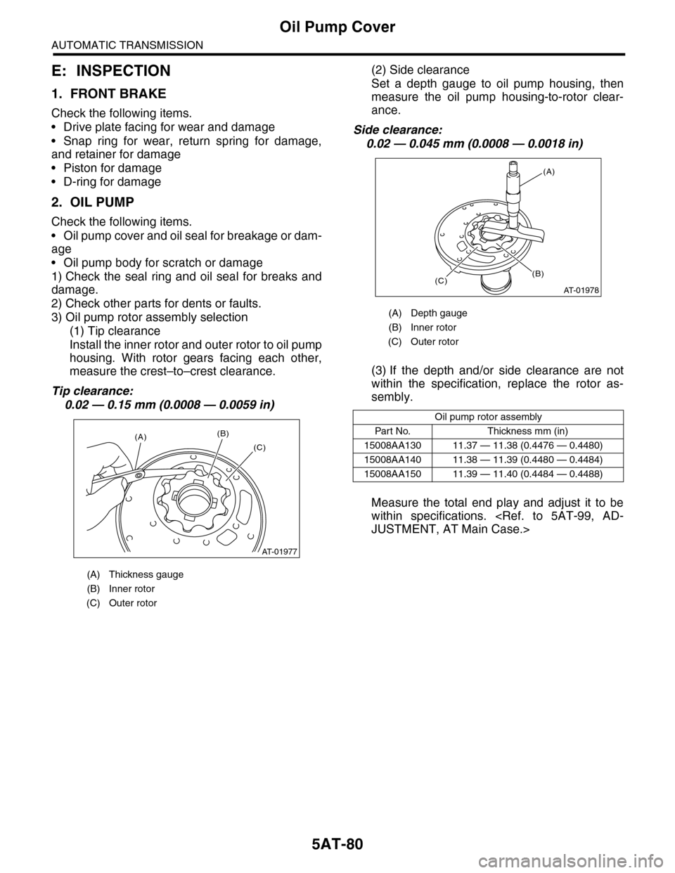
3) Oil pump rotor assembly selection
(1) Tip clearance
Install the inner rotor and outer rotor to oil pump
housing. With rotor gears facing each other,
measure the crest–to–crest clearance.
Tip clearance:
0.02 — 0.15 mm (0.0008 — 0.0059 in)
(2) Side clearance
Set a depth gauge to oil pump housing, then
measure the oil pump housing-to-rotor clear-
ance.
Side clearance:
0.02 — 0.045 mm (0.0008 — 0.0018 in)
(3) If the depth and/or side clearance are not
within the specification, replace the rotor as-
sembly.
Measure the total end play and adjust it to be
within specifications.
JUSTMENT, AT Main Case.>
(A) Thickness gauge
(B) Inner rotor
(C) Outer rotor
AT-01977
(A)(B)
(C)
(A) Depth gauge
(B) Inner rotor
(C) Outer rotor
Oil pump rotor assembly
Par t No. Thickness mm (in)
15008AA130 11.37 — 11.38 (0.4476 — 0.4480)
15008AA140 11.38 — 11.39 (0.4480 — 0.4484)
15008AA150 11.39 — 11.40 (0.4484 — 0.4488)
AT-01978
(A)
(C)(B)