2009 SUBARU TRIBECA Oil pump
[x] Cancel search: Oil pumpPage 2097 of 2453
5AT-81
Drive Pinion Shaft Assembly
AUTOMATIC TRANSMISSION
32.Drive Pinion Shaft Assembly
A: REMOVAL
1) Remove the transmission assembly from vehicle
body.
2) Pull out the torque converter assembly.
3) Remove the transmission harness connector
from stay.
4) Disconnect the air breather hose.
5) Remove the oil charge pipe.
6) Remove the ATF filter inlet and outlet pipes.
7) Separate the converter case and transmission
case.
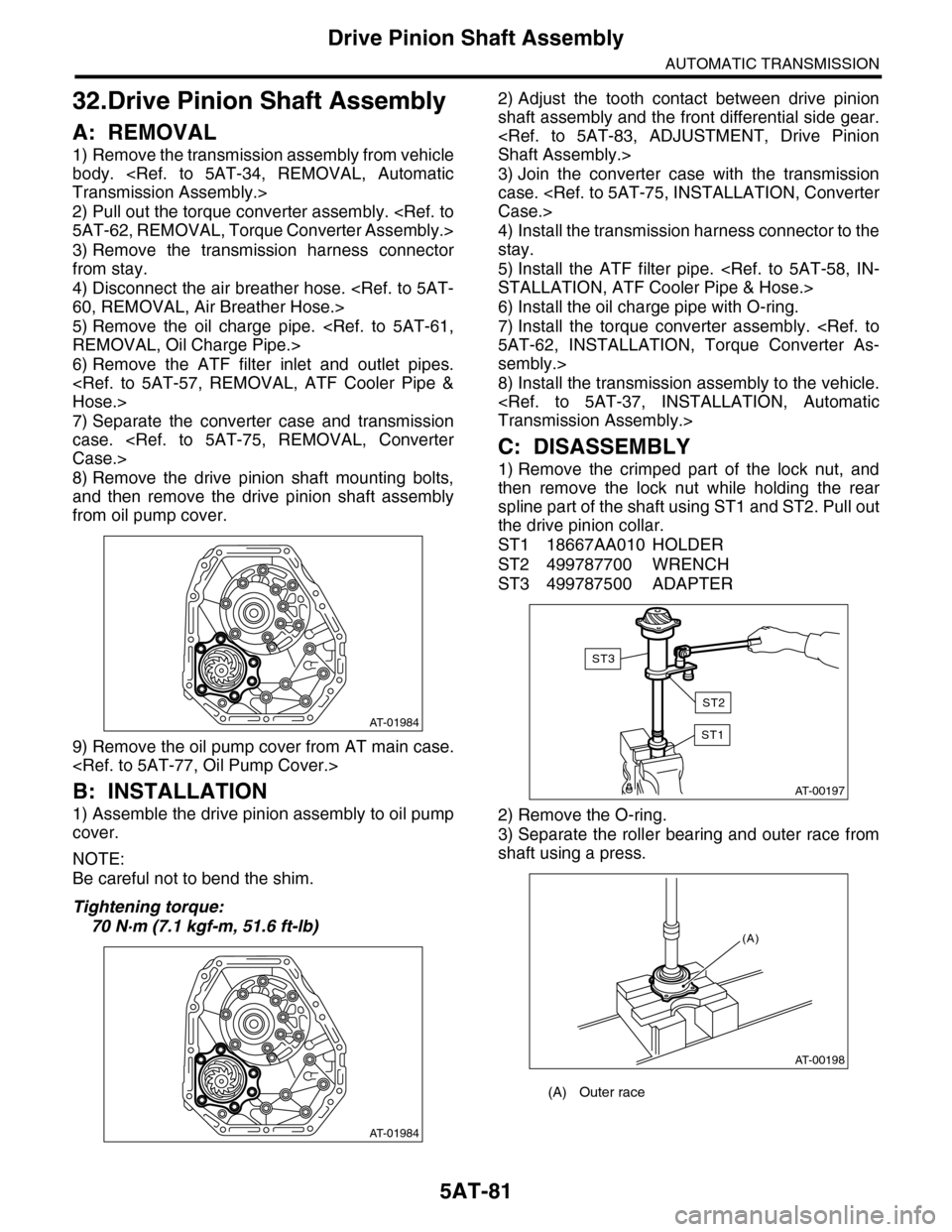
8) Remove the drive pinion shaft mounting bolts,
and then remove the drive pinion shaft assembly
from oil pump cover.
9) Remove the oil pump cover from AT main case.
B: INSTALLATION
1) Assemble the drive pinion assembly to oil pump
cover.
NOTE:
Be careful not to bend the shim.
Tightening torque:
70 N·m (7.1 kgf-m, 51.6 ft-lb)
2) Adjust the tooth contact between drive pinion
shaft assembly and the front differential side gear.
3) Join the converter case with the transmission
case.
4) Install the transmission harness connector to the
stay.
5) Install the ATF filter pipe.
6) Install the oil charge pipe with O-ring.
7) Install the torque converter assembly.
sembly.>
8) Install the transmission assembly to the vehicle.
C: DISASSEMBLY
1) Remove the crimped part of the lock nut, and
then remove the lock nut while holding the rear
spline part of the shaft using ST1 and ST2. Pull out
the drive pinion collar.
ST1 18667AA010 HOLDER
ST2 499787700 WRENCH
ST3 499787500 ADAPTER
2) Remove the O-ring.
3) Separate the roller bearing and outer race from
shaft using a press.
AT-01984
AT-01984
(A) Outer race
AT-00197
ST1
ST3
ST2
AT-00198
(A)
Page 2099 of 2453
5AT-83
Drive Pinion Shaft Assembly
AUTOMATIC TRANSMISSION
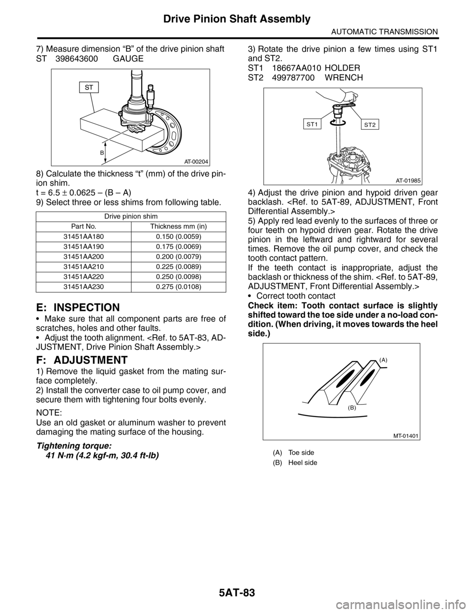
7) Measure dimension “B” of the drive pinion shaft
ST 398643600 GAUGE
8) Calculate the thickness “t” (mm) of the drive pin-
ion shim.
t = 6.5 ± 0.0625 – (B – A)
9) Select three or less shims from following table.
E: INSPECTION
•Make sure that all component parts are free of
scratches, holes and other faults.
•Adjust the tooth alignment.
F: ADJUSTMENT
1) Remove the liquid gasket from the mating sur-
face completely.
2) Install the converter case to oil pump cover, and
secure them with tightening four bolts evenly.
NOTE:
Use an old gasket or aluminum washer to prevent
damaging the mating surface of the housing.
Tightening torque:
41 N·m (4.2 kgf-m, 30.4 ft-lb)
3) Rotate the drive pinion a few times using ST1
and ST2.
ST1 18667AA010 HOLDER
ST2 499787700 WRENCH
4) Adjust the drive pinion and hypoid driven gear
backlash.
5) Apply red lead evenly to the surfaces of three or
four teeth on hypoid driven gear. Rotate the drive
pinion in the leftward and rightward for several
times. Remove the oil pump cover, and check the
tooth contact pattern.
If the teeth contact is inappropriate, adjust the
backlash or thickness of the shim.
•Correct tooth contact
Check item: Tooth contact surface is slightly
shifted toward the toe side under a no-load con-
dition. (When driving, it moves towards the heel
side.)
Drive pinion shim
Par t No. Thickness mm (in)
31451AA180 0.150 (0.0059)
31451AA190 0.175 (0.0069)
31451AA200 0.200 (0.0079)
31451AA210 0.225 (0.0089)
31451AA220 0.250 (0.0098)
31451AA230 0.275 (0.0108)
B
AT-00204
(A) Toe side
(B) Heel side
AT-01985
ST2ST1
MT-01401
(A)
(B)
Page 2105 of 2453
5AT-89
Front Differential Assembly
AUTOMATIC TRANSMISSION
2. SIDE RETAINER
NOTE:
Install the oil seal and O-ring of side retainer after
the adjustment of backlash and tooth contact.
1) Install the bearing outer race to side retainer.
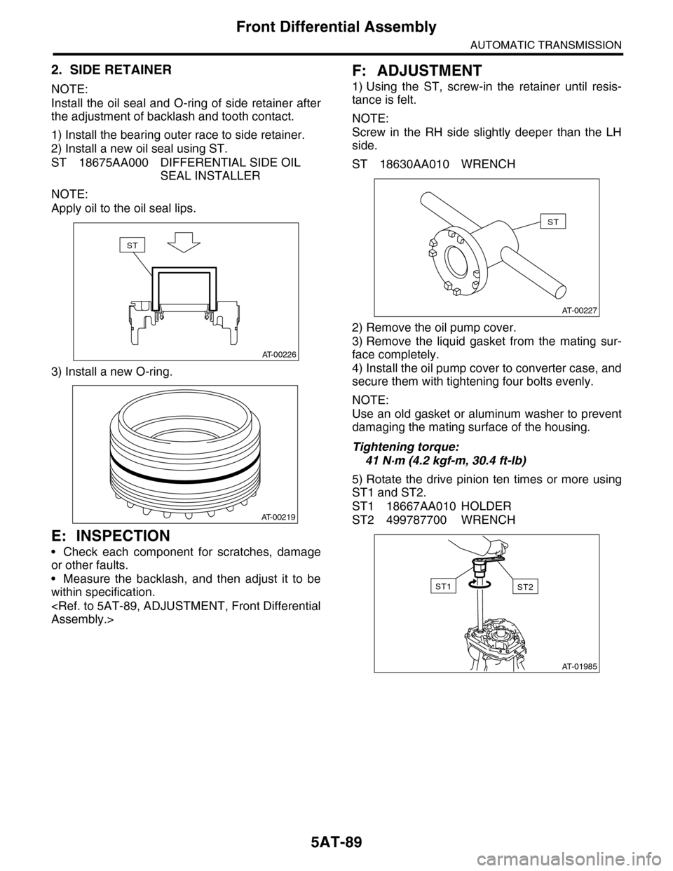
2) Install a new oil seal using ST.
ST 18675AA000 DIFFERENTIAL SIDE OIL
SEAL INSTALLER
NOTE:
Apply oil to the oil seal lips.
3) Install a new O-ring.
E: INSPECTION
•Check each component for scratches, damage
or other faults.
•Measure the backlash, and then adjust it to be
within specification.
F: ADJUSTMENT
1) Using the ST, screw-in the retainer until resis-
tance is felt.
NOTE:
Screw in the RH side slightly deeper than the LH
side.
ST 18630AA010 WRENCH
2) Remove the oil pump cover.
3) Remove the liquid gasket from the mating sur-
face completely.
4) Install the oil pump cover to converter case, and
secure them with tightening four bolts evenly.
NOTE:
Use an old gasket or aluminum washer to prevent
damaging the mating surface of the housing.
Tightening torque:
41 N·m (4.2 kgf-m, 30.4 ft-lb)
5) Rotate the drive pinion ten times or more using
ST1 and ST2.
ST1 18667AA010 HOLDER
ST2 499787700 WRENCH
AT-00226
ST
AT-00219
AT-00227
ST
AT-01985
ST2ST1
Page 2107 of 2453
5AT-91
AT Main Case
AUTOMATIC TRANSMISSION
34.AT Main Case
A: REMOVAL
1) Remove the transmission assembly from vehicle
body.
2) Pull out the torque converter assembly.
3) Remove the transmission harness connector
from stay.
4) Disconnect the air breather hose.
5) Remove the oil charge pipe.
6) Remove the ATF filter inlet and outlet pipes.
7) Remove the extension case.
8) Remove the center differential carrier.
9) Remove the reduction driven gear.
10) Separate the converter case from the transmis-
sion case.
11) Remove the control valve body.
12) Remove the oil pump cover.
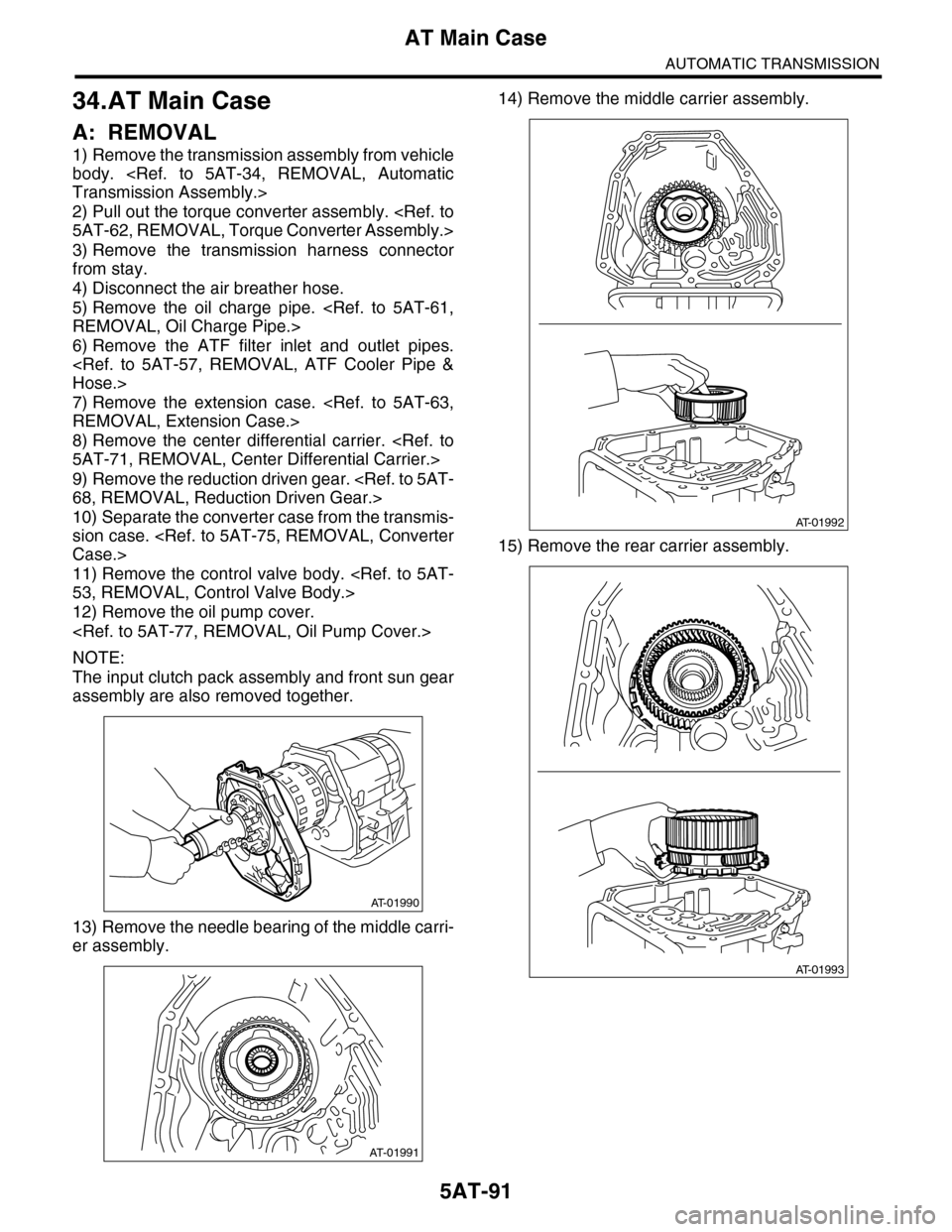
NOTE:
The input clutch pack assembly and front sun gear
assembly are also removed together.
13) Remove the needle bearing of the middle carri-
er assembly.
14) Remove the middle carrier assembly.
15) Remove the rear carrier assembly.
AT-01990
AT-01991
AT-01992
AT-01993
Page 2112 of 2453
5AT-96
AT Main Case
AUTOMATIC TRANSMISSION
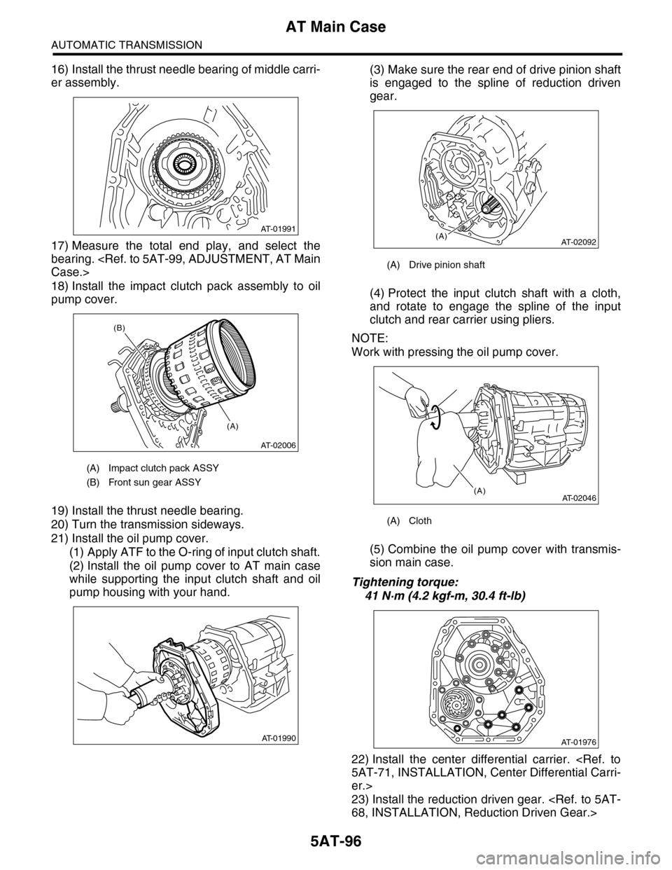
16) Install the thrust needle bearing of middle carri-
er assembly.
17) Measure the total end play, and select the
bearing.
18) Install the impact clutch pack assembly to oil
pump cover.
19) Install the thrust needle bearing.
20) Turn the transmission sideways.
21) Install the oil pump cover.
(1) Apply ATF to the O-ring of input clutch shaft.
(2) Install the oil pump cover to AT main case
while supporting the input clutch shaft and oil
pump housing with your hand.
(3) Make sure the rear end of drive pinion shaft
is engaged to the spline of reduction driven
gear.
(4) Protect the input clutch shaft with a cloth,
and rotate to engage the spline of the input
clutch and rear carrier using pliers.
NOTE:
Work with pressing the oil pump cover.
(5) Combine the oil pump cover with transmis-
sion main case.
Tightening torque:
41 N·m (4.2 kgf-m, 30.4 ft-lb)
22) Install the center differential carrier.
er.>
23) Install the reduction driven gear.
(A) Impact clutch pack ASSY
(B) Front sun gear ASSY
AT-01991
AT-02006
(A)
(B)
AT-01990
(A) Drive pinion shaft
(A) Cloth
AT-02092(A)
AT-02046(A)
AT-01976
Page 2115 of 2453
5AT-99
AT Main Case
AUTOMATIC TRANSMISSION
F: ADJUSTMENT
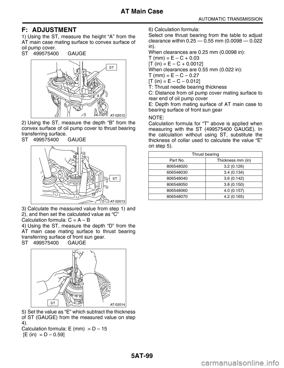
1) Using the ST, measure the height “A” from the
AT main case mating surface to convex surface of
oil pump cover.
ST 499575400 GAUGE
2) Using the ST, measure the depth “B” from the
convex surface of oil pump cover to thrust bearing
transferring surface.
ST 499575400 GAUGE
3) Calculate the measured value from step 1) and
2), and then set the calculated value as “C”
Calculation formula: C = A – B
4) Using the ST, measure the depth “D” from the
AT main case mating surface to thrust bearing
transferring surface of front sun gear.
ST 499575400 GAUGE
5) Set the value as “E” which subtract the thickness
of ST (GAUGE) from the measured value on step
4).
Calculation formula: E (mm) = D – 15
[E (in) = D – 0.59]
6) Calculation formula:
Select one thrust bearing from the table to adjust
clearance within 0.25 — 0.55 mm (0.0098 — 0.022
in).
When clearances are 0.25 mm (0.0098 in):
T (mm) = E – C + 0.03
[T (in) = E – C + 0.0012]
When clearances are 0.55 mm (0.022 in):
T (mm) = E – C – 0.27
[T (in) = E – C – 0.012]
T: Thrust needle bearing thickness
C: Distance from oil pump cover mating surface to
rear end of oil pump cover
E: Depth from mating surface of AT main case to
bearing surface of front sun gear
NOTE:
Calculation formula for “T” above is applied when
measuring with the ST (499575400 GAUGE). In
the calculation without using ST, substitute the
thickness of collar used to calculate the value “E”
on step 5).
AT-02012
ST
A
AT-02013
STB
AT-02014ST
D
Thrust bearing
Par t N o. Thickness mm (in)
806548020 3.2 (0.126)
606548030 3.4 (0.134)
806548040 3.6 (0.142)
806548050 3.8 (0.150)
806548060 4.0 (0.157)
806548070 4.2 (0.165)
Page 2316 of 2453
WI-32
Engine Electrical System
WIRING SYSTEM
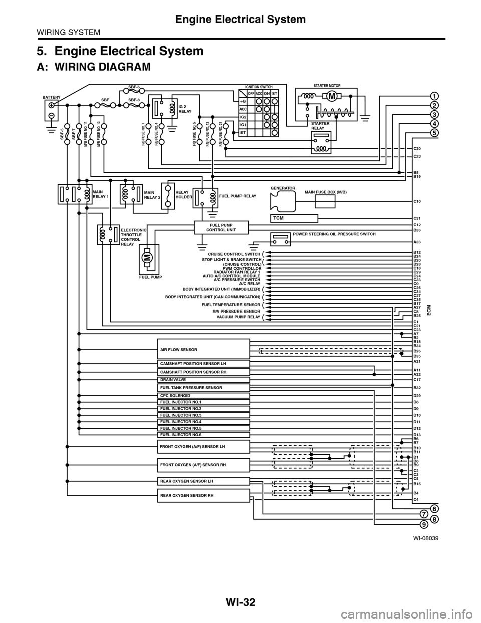
5. Engine Electrical System
A: WIRING DIAGRAM
WI-08039
678
1
2
3
4
5
C20
C32
C31
B5B19
B33
A33
C10
ECMC1B25C8A27
C21C23A7
D29
B2
BATTERY
M/B FUSE NO. 11SBF-7
SBF
SBF-5
SBF-8
SBF-6
STARTERRELAY
IG 2RELAY
IGNITION SWITCHOFF+B
ACC
IG2
IG1
ACCONST
ST
STARTER MOTOR
MAINRELAY 1
ELECTRONICTHROTTLECONTROLRELAY
FUEL PUMP RELAY
FUEL PUMP
FUEL PUMPCONTROL UNIT
MAINRELAY 2RELAYHOLDER
A21
A11A22
B34
B35
B7B6
B11B10
B9B8
C2
B26AIR FLOW SENSOR
CAMSHAFT POSITION SENSOR LH
CPC SOLENOID
B1
C3C5B15
B4C4
POWER STEERING OIL PRESSURE SWITCH
C12
MAIN FUSE BOX (M/B)GENERATOR
B18
TCM
D8FUEL INJECTOR NO.1D9D10D11
PWM CONTROLLORAUTO A/C CONTROL MODULE
A/C RELAY
BODY INTEGRATED UNIT (CAN COMMUNICATION)
FUEL TEMPERATURE SENSOR
VACUUM PUMP RELAY
BODY INTEGRATED UNIT (IMMOBILIZER)
C18C29C24C33
C27
B24B12
B20B28
C26C34
C35B17
CRUISE CONTROL SWITCH
FUEL INJECTOR NO.2FUEL INJECTOR NO.3
C17DRAIN VALVE
FUEL INJECTOR NO.4D12D13FUEL INJECTOR NO.5FUEL INJECTOR NO.6
FRONT OXYGEN (A/F) SENSOR RH
REAR OXYGEN SENSOR RH
REAR OXYGEN SENSOR LH
FRONT OXYGEN (A/F) SENSOR LH
A/C PRESSURE SWITCH
M/V PRESSURE SENSOR
RADIATOR FAN RELAY 1
STOP LIGHT & BRAKE SWITCH(CRUISE CONTROL)
C9
FUEL TANK PRESSURE SENSORB32
M/B FUSE NO. 13F/B FUSE NO. 7F/B FUSE NO. 4F/B FUSE NO. 5F/B FUSE NO. 12F/B FUSE NO. 21
CAMSHAFT POSITION SENSOR RH
9
Page 2445 of 2453
WI-161
Rear Wiring Harness
WIRING SYSTEM
60.Rear Wiring Harness
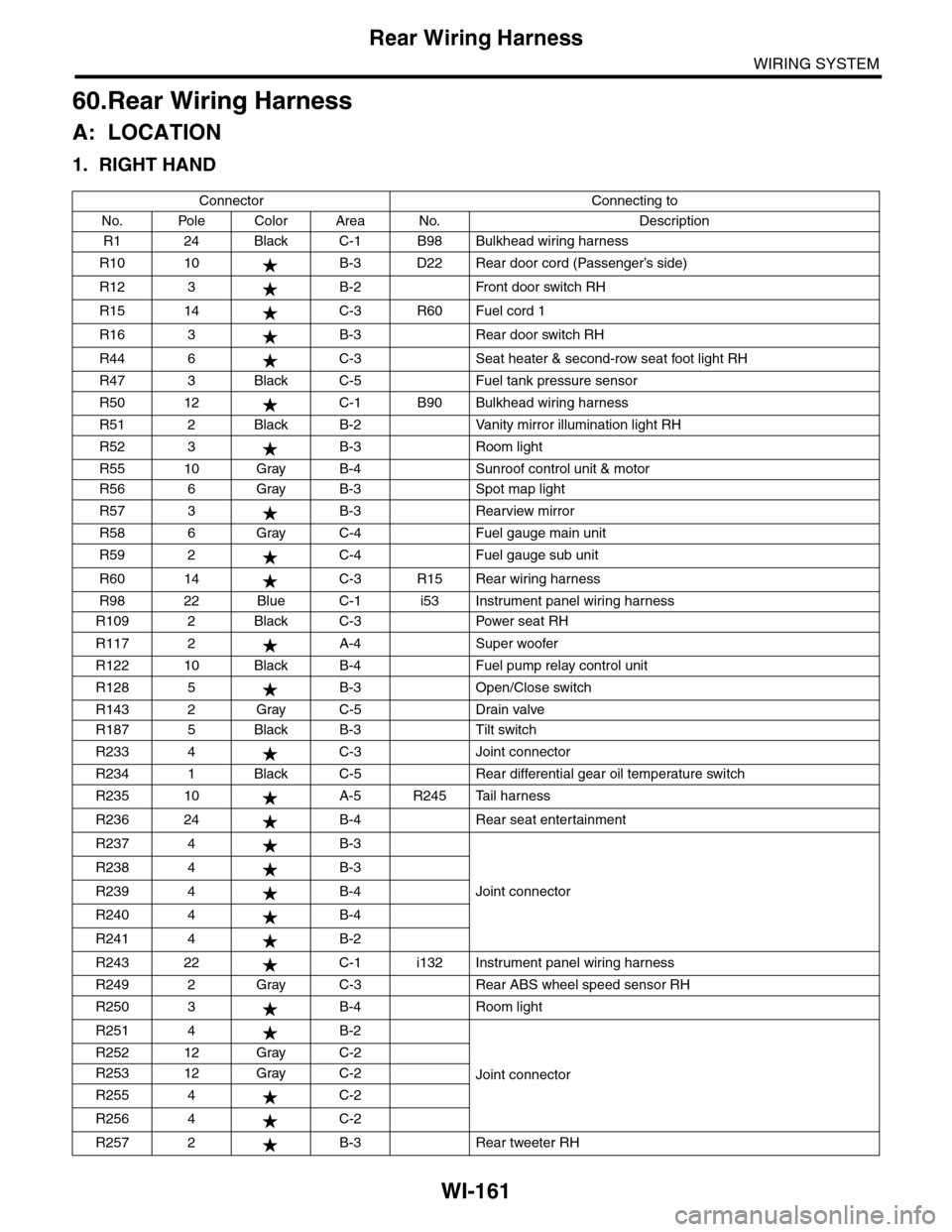
A: LOCATION
1. RIGHT HAND
Connector Connecting to
No. Pole Color Area No. Description
R1 24 Black C-1 B98 Bulkhead wiring harness
R10 10 B-3 D22 Rear door cord (Passenger’s side)
R12 3 B-2 Front door switch RH
R15 14 C-3 R60 Fuel cord 1
R16 3 B-3 Rear door switch RH
R44 6 C-3 Seat heater & second-row seat foot light RH
R47 3 Black C-5 Fuel tank pressure sensor
R50 12 C-1 B90 Bulkhead wiring harness
R51 2 Black B-2 Vanity mirror illumination light RH
R52 3 B-3 Room light
R55 10 Gray B-4 Sunroof control unit & motor
R56 6 Gray B-3 Spot map light
R57 3 B-3 Rearview mirror
R58 6 Gray C-4 Fuel gauge main unit
R59 2 C-4 Fuel gauge sub unit
R60 14 C-3 R15 Rear wiring harness
R98 22 Blue C-1 i53 Instrument panel wiring harness
R109 2 Black C-3 Power seat RH
R117 2 A-4 Super woofer
R122 10 Black B-4 Fuel pump relay control unit
R128 5 B-3 Open/Close switch
R143 2 Gray C-5 Drain valve
R187 5 Black B-3 Tilt switch
R233 4 C-3 Joint connector
R234 1 Black C-5 Rear differential gear oil temperature switch
R235 10 A-5 R245 Tail harness
R236 24 B-4 Rear seat entertainment
R237 4 B-3
Joint connector
R238 4 B-3
R239 4 B-4
R240 4 B-4
R241 4 B-2
R243 22 C-1 i132 Instrument panel wiring harness
R249 2 Gray C-3 Rear ABS wheel speed sensor RH
R250 3 B-4 Room light
R251 4 B-2
Joint connector
R252 12 Gray C-2
R253 12 Gray C-2
R255 4 C-2
R256 4 C-2
R257 2 B-3 Rear tweeter RH