Page 1853 of 2453

LU(H6DO)-4
General Description
LUBRICATION
C: CAUTION
•Wear work clothing, including a cap, protective goggles and protective shoes during operation.
•Remove contamination including dirt and corrosion before removal, installation or disassembly.
•Keep the disassembled parts in order and protect them from dust and dirt.
•Before removal, installation or disassembly, be sure to clarify the failure. Avoid unnecessary removal, in-
stallation, disassembly and replacement.
•Be careful not to burn yourself, because each part on the vehicle is hot after running.
•Be sure to tighten fasteners including bolts and nuts to the specified torque.
•Place shop jacks or rigid racks at the specified points.
•Before disconnecting connectors of sensors or units, be sure to disconnect the ground cable from battery.
D: PREPARATION TOOL
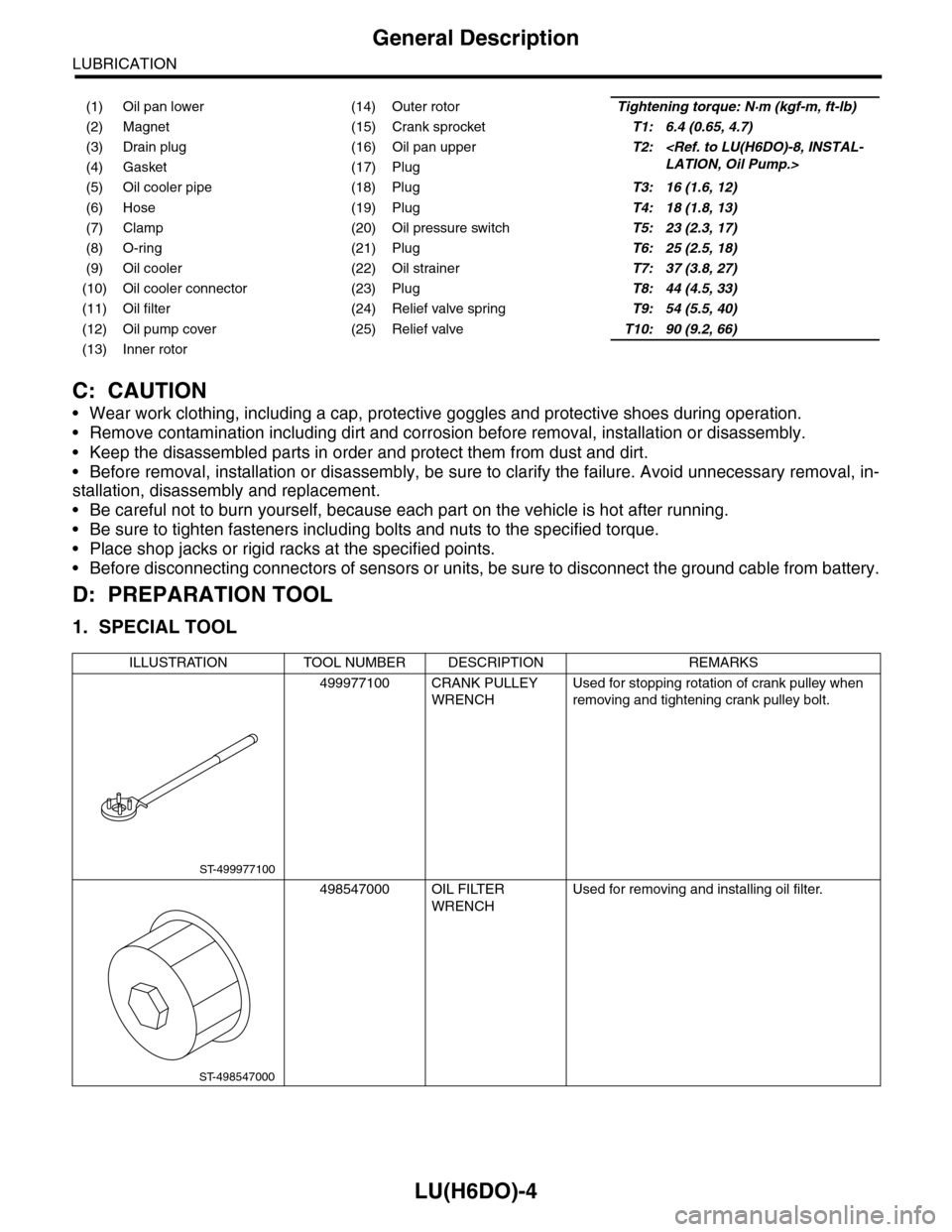
1. SPECIAL TOOL
(1) Oil pan lower (14) Outer rotorTightening torque: N·m (kgf-m, ft-lb)
(2) Magnet (15) Crank sprocketT1: 6.4 (0.65, 4.7)
(3) Drain plug (16) Oil pan upperT2:
LATION, Oil Pump.>(4) Gasket (17) Plug
(5) Oil cooler pipe (18) PlugT3: 16 (1.6, 12)
(6) Hose (19) PlugT4: 18 (1.8, 13)
(7) Clamp (20) Oil pressure switchT5: 23 (2.3, 17)
(8) O-ring (21) PlugT6: 25 (2.5, 18)
(9) Oil cooler (22) Oil strainerT7: 37 (3.8, 27)
(10) Oil cooler connector (23) PlugT8: 44 (4.5, 33)
(11) Oil filter (24) Relief valve springT9: 54 (5.5, 40)
(12) Oil pump cover (25) Relief valveT10: 90 (9.2, 66)
(13) Inner rotor
ILLUSTRATION TOOL NUMBER DESCRIPTION REMARKS
499977100 CRANK PULLEY
WRENCH
Used for stopping rotation of crank pulley when
removing and tightening crank pulley bolt.
498547000 OIL FILTER
WRENCH
Used for removing and installing oil filter.
ST-499977100
ST-498547000
Page 1857 of 2453

LU(H6DO)-8
Oil Pump
LUBRICATION
4. Oil Pump
A: REMOVAL
1) Remove the collector cover.
2) Disconnect the ground cable from battery.
3) Lift-up the vehicle.
4) Remove the under cover.
5) Drain engine coolant.
DRAINING OF ENGINE COOLANT, REPLACE-
MENT, Engine Coolant.>
6) Lower the vehicle.
7) Remove the radiator.
REMOVAL, Radiator.>
8) Remove the V-belts.
REMOVAL, V-belt.>
9) Remove the front chain cover.
ME(H6DO)-42, REMOVAL, Front Chain Cover.>
10) Remove the timing chain.
44, REMOVAL, Timing Chain Assembly.>
11) Remove the crank sprocket.
12) Remove the oil pump cover.
13) Remove the inner rotor and outer rotor.
B: INSTALLATION
1) Apply a coat of engine oil to the whole area of in-
ner rotor and outer rotor.
2) Set the inner rotor onto opening edge of crank
shaft, and install the inner rotor, and then assemble
the outer rotor.
3) Install the oil pump cover.
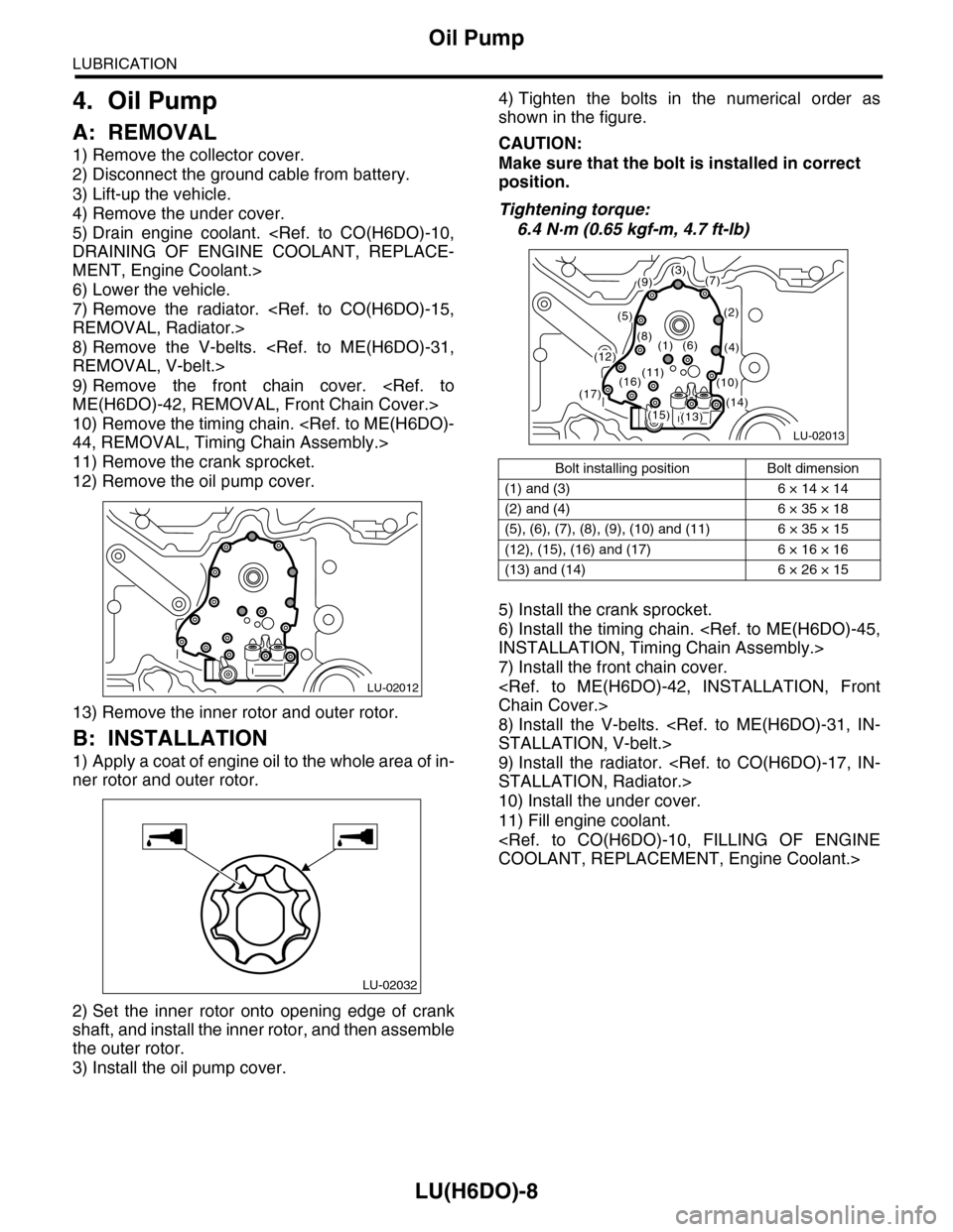
4) Tighten the bolts in the numerical order as
shown in the figure.
CAUTION:
Make sure that the bolt is installed in correct
position.
Tightening torque:
6.4 N·m (0.65 kgf-m, 4.7 ft-lb)
5) Install the crank sprocket.
6) Install the timing chain.
INSTALLATION, Timing Chain Assembly.>
7) Install the front chain cover.
Chain Cover.>
8) Install the V-belts.
STALLATION, V-belt.>
9) Install the radiator.
STALLATION, Radiator.>
10) Install the under cover.
11) Fill engine coolant.
COOLANT, REPLACEMENT, Engine Coolant.>
LU-02012
LU-02032
Bolt installing position Bolt dimension
(1) and (3) 6 × 14 × 14
(2) and (4) 6 × 35 × 18
(5), (6), (7), (8), (9), (10) and (11) 6 × 35 × 15
(12), (15), (16) and (17) 6 × 16 × 16
(13) and (14) 6 × 26 × 15
LU-02013
(3)(7)
(2)
(4)
(9)
(5)
(8)(1)(6)(12)
(13)(14)(15)
(16)(17)
(11)(10)
Page 1858 of 2453
LU(H6DO)-9
Oil Pump
LUBRICATION
C: INSPECTION
1. TIP CLEARANCE
Measure the tip clearance of rotors. If the clearance
exceeds specification, replace the rotors as a
matched set.
Tip clearance:
Specification
0.04 — 0.14 mm (0.0016 — 0.0055 in)
2. CASE CLEARANCE
Measure the clearance between the outer rotor and
rear chain cover rotor housing. If the clearance ex-
ceeds the standard value, replace the outer rotor.
Case clearance:
Specification
0.110 — 0.175 mm (0.0043 — 0.0069 in)
3. SIDE CLEARANCE
Measure the clearance between oil pump inner ro-
tor and rear chain cover. If the clearance exceeds
specification, replace the rotors as a matched set.
Side clearance:
Specification
0.020 — 0.046 mm (0.0008 — 0.0018 in)
4. OIL PUMP CASE
Check the worn shaft hole, clogged oil passage,
crank and other parts for faults.
LU-02014
LU-02015
LU-02016
Page 1859 of 2453

LU(H6DO)-10
Oil Pump Relief Valve
LUBRICATION
5. Oil Pump Relief Valve
A: REMOVAL
1. REAR CHAIN COVER SIDE
Oil pump relief valve is integrated into oil pump cov-
er as one unit; therefore, refer to “Oil Pump” for re-
moval procedure.
REMOVAL, Oil Pump.>
2. OIL PAN UPPER SIDE
1) Remove the oil pan.
MOVAL, Oil Pan and Strainer.>
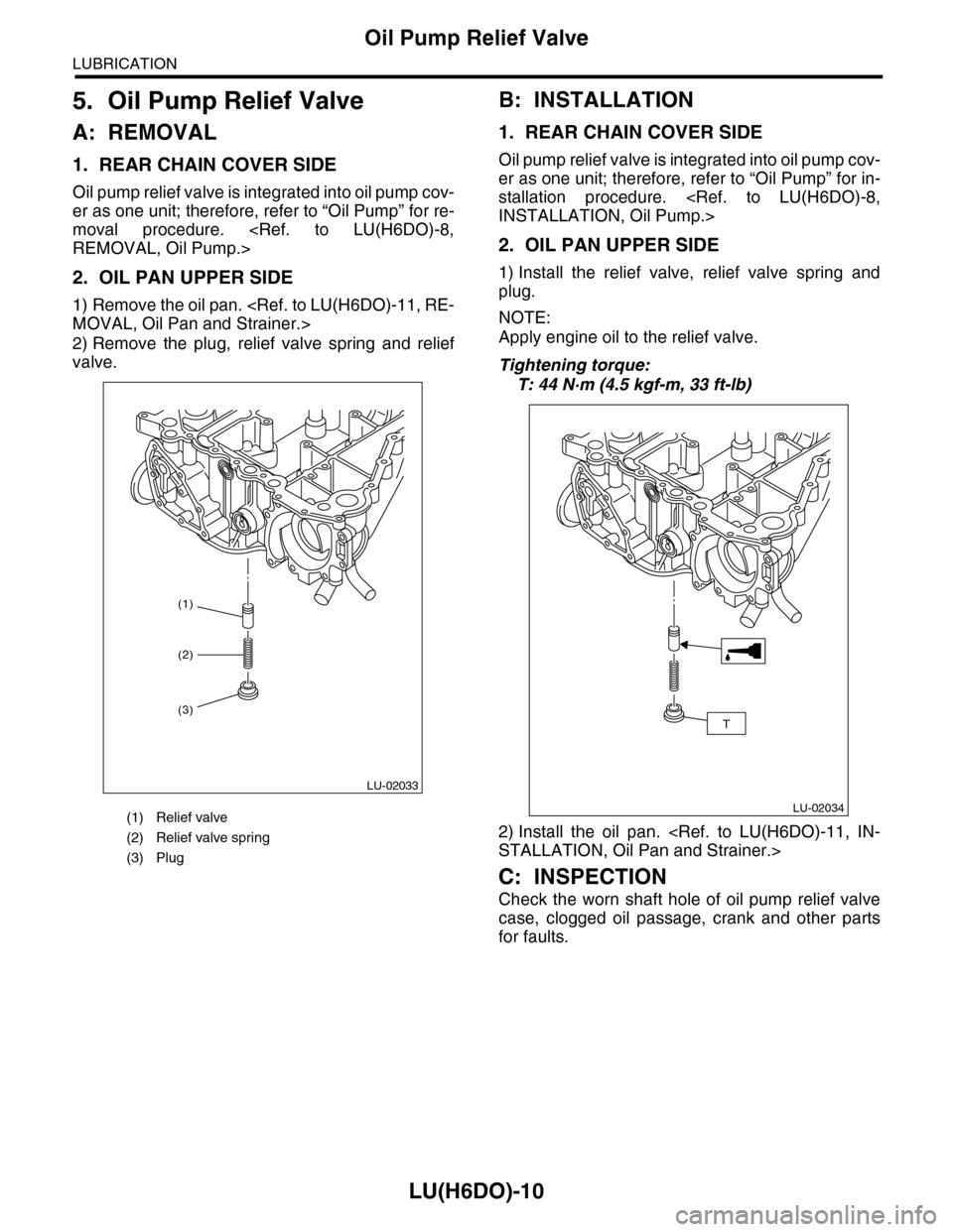
2) Remove the plug, relief valve spring and relief
valve.
B: INSTALLATION
1. REAR CHAIN COVER SIDE
Oil pump relief valve is integrated into oil pump cov-
er as one unit; therefore, refer to “Oil Pump” for in-
stallation procedure.
INSTALLATION, Oil Pump.>
2. OIL PAN UPPER SIDE
1) Install the relief valve, relief valve spring and
plug.
NOTE:
Apply engine oil to the relief valve.
Tightening torque:
T: 44 N·m (4.5 kgf-m, 33 ft-lb)
2) Install the oil pan.
STALLATION, Oil Pan and Strainer.>
C: INSPECTION
Check the worn shaft hole of oil pump relief valve
case, clogged oil passage, crank and other parts
for faults.
(1) Relief valve
(2) Relief valve spring
(3) Plug
(1)
LU-02033
(2)
(3)
LU-02034
T
Page 1866 of 2453

LU(H6DO)-17
General Diagnostics Table
LUBRICATION
10.General Diagnostics Table
A: INSPECTION
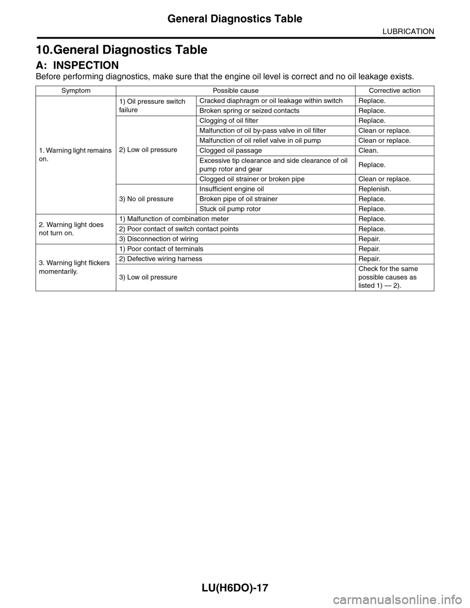
Before performing diagnostics, make sure that the engine oil level is correct and no oil leakage exists.
Symptom Possible cause Corrective action
1. Warning light remains
on.
1) Oil pressure switch
failure
Cracked diaphragm or oil leakage within switch Replace.
Broken spring or seized contacts Replace.
2) Low oil pressure
Clogging of oil filter Replace.
Malfunction of oil by-pass valve in oil filter Clean or replace.
Malfunction of oil relief valve in oil pump Clean or replace.
Clogged oil passage Clean.
Excessive tip clearance and side clearance of oil
pump rotor and gearReplace.
Clogged oil strainer or broken pipe Clean or replace.
3) No oil pressure
Insufficient engine oil Replenish.
Broken pipe of oil strainer Replace.
Stuck oil pump rotor Replace.
2. Warning light does
not turn on.
1) Malfunction of combination meter Replace.
2) Poor contact of switch contact points Replace.
3) Disconnection of wiring Repair.
3. Warning light flickers
momentarily.
1) Poor contact of terminals Repair.
2) Defective wiring harness Repair.
3) Low oil pressure
Check for the same
possible causes as
listed 1) — 2).
Page 1872 of 2453
ME(H6DO)-6
General Description
MECHANICAL
2. TIMING CHAIN COVER
(1) Crank pulley coverTightening torque: N·m (kgf-m, ft-lb)
(2) O-ringT1:
Pulley.>(3) Crank pulley
(4) Sealing washerT2:
Chain Cover.>(5) Oil seal
(6) Front chain cover T3:
Chain Cover.>(7) Rear chain cover
(8) Water pump gasket T4: 6.4 (0.65, 4.7)
ME-02021
T2
T2
T2
T2
T3T3
T3
T3
T3
(4)
(6)
(7)
(8)
(5)
T1
T4
(1)
(3)
(2)
Page 1873 of 2453
ME(H6DO)-7
General Description
MECHANICAL
3. TIMING CHAIN
(1) Crank sprocket (13) Chain tensioner lever (LH) (24) Idler sprocket (upper)
(2) Oil relief case (14) Chain tensioner (LH)
(3) Inner rotor (15) Water pumpTightening torque: N·m (kgf-m, ft-lb)
(4) Outer rotor (16) O-ringT1:6.4 (0.65, 4.7)
(5) Chain guide (center) (17) Chain guide (LH)T2: 7.8 (0.8, 5.8)
(6) Intake cam sprocket (RH) (18) Chain guide (LH: between cams)T3:
Sprocket.>(7) Exhaust cam sprocket (RH) (19) Timing chain (LH)
(8) Chain guide (RH: between cams) (20) Intake cam sprocket (LH)T4: 16 (1.6, 12)
(9) Timing chain (RH) (21) Exhaust cam sprocket (LH)T5: 69 (7.0, 50.6)
(10) Chain guide (RH) (22) Idler sprocket (lower)T6:
Pump.>(11) Chain tensioner lever (RH) (23) Idler sprocket collar
(12) Chain tensioner (RH)
ME-02380
T6
(2)
(8)
(9)
(10)
(11)
(12)
(13)
(14)
(15)(16)
(17)
(18)(19)
(5)
T3
T3
T5
T2
T1
T1
T1
T4
T4
T4
T4
T4
(7)
(21)
(20)
(22)
(23)
(23)
(24)
(6)
(1)
(3)
(4)
Page 1891 of 2453
ME(H6DO)-25
Engine Oil Pressure
MECHANICAL
6. Engine Oil Pressure
A: INSPECTION
1) Remove the oil pressure switch from cylinder
block.
Pressure Switch.>
2) Connect the oil pressure gauge hose to cylinder
block.
3) Connect the ground cable to the battery.
4) Start the engine, and measure the oil pressure.
OIL PRESSURE (at oil temperature of 80°C
(176°F)):
Standard:
135 kPa (1.4 kgf/cm2, 20 psi) or more (at
600 rpm)
500 kPa (5.1 kgf/cm2, 73 psi) or more (at
5,000 rpm)
CAUTION:
•If the oil pressure is out of specification,
check oil pump, oil filter and lubrication line.
Diagnostics Table.>
•If the oil pressure warning light is turned ON
and oil pressure is in specification, replace the
oil pressure switch.
SPECTION, General Diagnostics Table.>
5) After measuring the oil pressure, install the oil
pressure switch.
LATION, Oil Pressure Switch.>
Tightening torque:
25 N·m (2.5 kgf-m, 18 ft-lb)