2009 SUBARU TRIBECA coolant temperature
[x] Cancel search: coolant temperaturePage 391 of 2453

AC(diag)-14
Diagnostic Chart for Self-diagnosis
HVAC SYSTEM (AUTO A/C) (DIAGNOSTICS)
4. SENSOR CHECK TABLE
NOTE:
When the sunload sensor check is performed indoors or in the shade, it could be diagnosed as having an
open circuit. Always check the sunload sensor with the sun shining on it.
*1: “AUTO” display does not blink when past malfunction occurred. Past malfunction means that abnormal signals were contin-
uously input for a certain time in the past.
*2: Present malfunction only is displayed for sunload sensor open circuit.
5. OPERATING MODE TABLE
*Same opening angle for both driver’s and passenger’s side
Display screen (Malfunction at
present) *1Sensor Trouble contents
21/AUTO BlinkIn-vehicle sensorOpen
–21/AUTO BlinkShort
22/AUTO Blink Ambient sensor Sensor trouble or communication malfunction
23/AUTO BlinkEvaporator sensorOpen
–23/AUTO BlinkShort
24/AUTO Blink Engine coolant temperature sensor Sensor trouble or communication malfunction
25 BlinkSunload sensorOpen *2
–25/AUTO BlinkShort
26/AUTO BlinkDriver's side air mix door actuator
potentiometer
COOL
27/AUTO BlinkHOT
–26/AUTO BlinkPassenger’s side air mix door actua-
tor potentiometer
COOL
–27/AUTO BlinkHOT
28/AUTO BlinkMode door actuator potentiometerFA C E
29/AUTO BlinkDEF
41/AUTO BlinkSeat heater thermistor (Driver’s
side)
Open
–41/AUTO BlinkShort
42/AUTO BlinkSeat heater thermistor (Passenger’s
side)
Open
–42/AUTO BlinkShort
20 Blink When all conditions are normal
Display screenFRESH/RECIRC
doorMode door Air mix door* Blower fanA/C compressor (Mag-
net clutch)
31 FRESH FACE Maximum cool LO OFF
32 RECIRC FACE Maximum cool LO ON
33 RECIRC FACE Maximum cool M1 ON
34 FRESH B/L 50% M1 ON
35 FRESH HEAT 50% M1 ON
36 FRESH HEAT Maximum hot M3 ON
37 FRESH D/H Maximum hot M3 ON
38 FRESH DEF Maximum hot HI ON
Page 441 of 2453

IDI-2
General Description
INSTRUMENTATION/DRIVER INFO
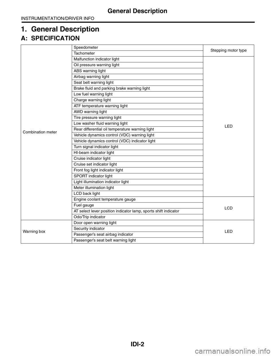
1. General Description
A: SPECIFICATION
Combination meter
SpeedometerStepping motor typeTa c h o m e t e r
Malfunction indicator light
LED
Oil pressure warning light
ABS warning light
Airbag warning light
Seat belt warning light
Brake fluid and parking brake warning light
Low fuel warning light
Charge warning light
AT F t e m p e r a t u r e w a r n i n g l i g h t
AW D war n in g l i gh t
Tire pressure warning light
Low washer fluid warning light
Rear differential oil temperature warning light
Ve h i c l e d y n a m i c s c o n t r o l ( V D C ) w a r n i n g l i g h t
Ve h i c l e d y n a m i c s c o n t r o l ( V D C ) i n d i c a t o r l i g h t
Tu r n s i g n a l i n d i c a t o r l i g h t
HI-beam indicator light
Cruise indicator light
Cruise set indicator light
Fr o nt fog li g ht i nd i ca to r li g ht
SPORT indicator light
Light illumination indicator light
Meter illumination light
LCD back light
Engine coolant temperature gauge
LCDFuel gauge
AT s e l e c t l e v e r p o s i t i o n i n d i c a t o r l a m p , s p o r t s s h i f t i n d i c a t o r
Odo/Trip indicator
Wa r ni n g b ox
Door open warning light
LEDSecurity indicator
Passenger’s seat airbag indicator
Passenger’s seat belt war ning light
Page 446 of 2453

IDI-7
Combination Meter System
INSTRUMENTATION/DRIVER INFO
3. SYMPTOM CHART
CAUTION:
When measuring the voltage and resistance of each control module or sensor, use a tapered pin with
a diameter of less than 0.64 mm (0.025 in) in order to avoid poor contact. Do not insert the pin more
than 2 mm (0.08 in).
4. CHECK POWER SUPPLY AND GROUND CIRCUIT
Symptom Repair order Note
Combination meter assembly does not
operate.
1. Power supply
2. Ground circuit
3. Combination meter
Combination Meter System.>
Speedometer does not operate. 1. VDCCM
2. Harness
3. Combination meter
tem.>
Ta c h o m e t e r d o e s n o t o p e r a t e . 1 . E C M
2. Harness
3. Combination meter
Combination Meter System.>
Fuel gauge does not operate. 1. Communication circuit
2. Fuel level sensor
3. Harness
4. Combination meter
Meter System.>
Engine coolant temperature gauge does
not operate.
1. Communication circuit
2. Engine coolant temperature sensor
3. Harness
4. Combination meter
INSPECTION, Combination Meter Sys-
tem.>
Error display is shown on the odo/trip
meter.
Communication circuit
nation Meter System.>
Step Check Yes No
1CHECK POWER SUPPLY FOR COMBINA-
TION METER.
1) Remove the combination meter.
2) Disconnect the combination meter harness
connector.
3) Turn the ignition switch to ON.
4) Measure the voltage between combination
meter connector and chassis ground.
Connector & terminal
(i10) No. 3, 4 (+) — Chassis ground (–):
Is the voltage more than 10 V? Go to step 2.Check the harness
for open or shor t
between the igni-
tion switch and
combination
meter.
2CHECK POWER SUPPLY FOR COMBINA-
TION METER.
Measure the voltage between combination
meter connector and chassis ground.
Connector & terminal
(i10) No. 1, 2 (+) — Chassis ground (–):
Is the voltage more than 10 V? Go to step 3.Check the harness
for open or shor t
between the fuse
and combination
meter.
3CHECK GROUND CIRCUIT OF COMBINA-
TION METER.
1) Turn the ignition switch to OFF.
2) Measure the resistance of harness
between combination meter connector and
chassis ground.
Connector & terminal
(i10) No. 15, 16 — Chassis ground:
Is the resistance less than 10
Ω?
Replace the meter
case assembly.
Repair the wiring
harness.
Page 449 of 2453

IDI-10
Combination Meter System
INSTRUMENTATION/DRIVER INFO
8. CHECK ENGINE COOLANT TEMPERATURE SENSOR.
9. COMMUNICATION ERROR DISPLAY
When the following error code is displayed in the
odo/trip meter, inspect the communication circuit
since the communication malfunction is generated
between each control module.
10.DTC DISPLAY MODE
When DTC display mode is operated, {ECM}, {TCM} is displayed repeatedly in this order by pressing the trip
knob. DTC is displayed in the following table according to type of control module, receiving DTC, DTC de-
tected, No DTC. If CAN communication has some trouble, “-----” is displayed.
Step Check Yes No
1CHECK COMMUNICATION ERROR DIS-
PLAY.
1) Turn the ignition switch to ON.
2) Check that the error code is displayed in
odo/trip meter.
Is the error code “Er xx” dis-
played in odo/trip meter?
Check the commu-
nication circuit.
TION ERROR
DISPLAY,
INSPECTION,
Combination
Meter System.>
Go to step 2.
2CHECK ENGINE COOLANT TEMPERATURE
SENSOR.
Check the engine coolant temperature sensor.
Is the engine coolant tempera-
ture sensor OK?
Replace the meter
case assembly.
Replace the
engine coolant
temperature sen-
sor.
IDI00188
Error code Description
Er IUMalfunction in integrated
module
Er ––
Simultaneous malfunction of
high/low speed CAN com-
munication
Er HCHigh speed CAN communi-
cation malfunction
Er LCMalfunction of low-speed
CAN communication
Er EGEGI Communication mal-
function
Er TCTCM Communication mal-
function
Er AbVDCCM communication
malfunction
Er SP
VDCCM DTC information
and vehicle speed pulse
malfunction
Er SSWheel speed data malfunc-
tion
Er bbVa c u u m p u m p s y s t e m m a l -
function
Control module Condition Display
ECM
Receiving DTC Trip “A” + “P (Blink)”
DTC detected Trip “A” + “P xxxx”
No DTC Trip “A” + “P ----”
TCM
Receiving DTC Trip “B” + “P (Blink)”
DTC detected Trip “B” + “P xxxx”
No DTC Trip “B” + “P ----”
When CAN communication error
is occurred—“-----”
Page 455 of 2453

IDI-16
Engine Coolant Temperature Gauge
INSTRUMENTATION/DRIVER INFO
7. Engine Coolant Temperature
Gauge
A: SPECIFICATION
Since the meter case assembly cannot be disas-
sembled, do not remove or inspect the temperature
gauge alone. (Do not remove the cover on the back
side.)
Page 459 of 2453

LAN(diag)-3
Check List for Interview
LAN SYSTEM (DIAGNOSTICS)
2. Check List for Interview
A: CHECK
Inspect the following item about the vehicle’s state.
1. DISPLAY OF COMMUNICATION ERROR
2. DISPLAY IN COMBINATION METER
Communication error is
displayed in odo/trip meter.
When and how often are they displayed?
Always
Sometimes
Only once
Which communication error is displayed? (Record them all)
Er IU (Fail in the body integrated unit)
Er HC (Fail of high-speed CAN)
Er LC (Fail of low-speed CAN)
Er –– (Fails of both high-speed and low-speed CAN)
Er EG (Fail of EGI communication data)
Er TC (fail of TCM communication data)
Er Ab (Fail of vehicle dynamics control (VDC)/ABS communication data)
Er bb (Fail of brake vacuum system)
Ignition key position OFF
ACC
ON (Before starting engine)
START
ON (After starting Engine, engine is running)
ON (After starting Engine, engine is at a standstill)
Timing Immediately after turning the ignition to ON.
Immediately after turning the ignition to START.
Display in combination
meter
a) Display of engine coolant temperature gauge OK / NG
b) Display of fuel gauge OK / NG
Display of other indicators c) Malfunction indicator light ON / OFF
d) SPORT indicator light (AT warning light) ON / OFF
e) ABS warning light/Vehicle dynamics control (VDC) warning
light ON / OFF
f) Security indicator light ON / Blink / OFF
g) Seat belt warning light (Driver’s seat) ON / OFF
h) Seat belt warning light (Passenger’s seat) ON / OFF
Page 469 of 2453
![SUBARU TRIBECA 2009 1.G Service Workshop Manual LAN(diag)-13
Subaru Select Monitor
LAN SYSTEM (DIAGNOSTICS)
2. READ CURRENT DATA
1) On the «Main Menu» display screen, select the {Each System Check} and press the [YES] key.
2) On the «System Sele SUBARU TRIBECA 2009 1.G Service Workshop Manual LAN(diag)-13
Subaru Select Monitor
LAN SYSTEM (DIAGNOSTICS)
2. READ CURRENT DATA
1) On the «Main Menu» display screen, select the {Each System Check} and press the [YES] key.
2) On the «System Sele](/manual-img/17/7322/w960_7322-468.png)
LAN(diag)-13
Subaru Select Monitor
LAN SYSTEM (DIAGNOSTICS)
2. READ CURRENT DATA
1) On the «Main Menu» display screen, select the {Each System Check} and press the [YES] key.
2) On the «System Selection Menu» display screen, select the {Integ. Unit mode} and press the [YES] key.
3) On the «Integ. unit mode failure diag» display screen, select the {Current Data Display & Save} and press
the [YES] key.
4) On the «Current Data Display & Save» display screen, select the {12 Data Display} and press the [YES]
key.
5) Using the scroll key, scroll the display screen up or down until the desired data is shown.
•A support list contains both of analog and digital data, and they are shown in the following table.
3. DISPLAY OF ANALOG DATA
Items to be displayed Unit of measure Description Note
BATT Voltage (Control) 10 — 15 VBody integrated unit input
valueAlways
BATT Voltage (BACK UP) 10 — 15 VBody integrated unit input
valueAlways
IG power supply voltage 10 — 15 VBody integrated unit input
valueIgnition switch ON
ACC voltage 10 — 15 VBody integrated unit input
valueIgnition switch ACC
Illumination VR voltage 0 — 5 VBody integrated unit out-
put valueSmall light switch ON
Illumi. output d-ratio 0 — 100%Body integrated unit input
value
Small light ON
Illumination volume is other than bright.
Ambient temp sensor V 0 — 5 VBody integrated unit out-
put valueIgnition switch ON
Ambient temperature –40 — 87.5°CBody integrated unit out-
put valueIgnition switch ON
Fuel level voltage 0 — 8 VBody integrated unit input
valueIgnition switch ON
Fuel level resistance 0 — 102.3 ΩBody integrated unit input
valueIgnition switch ON
key-lock solenoid V 6 — 12 VBody integrated unit out-
put value
Other than parking range
Ignition ON
number of regist. 0 — 4 Key No. to register
Fr o nt W he e l S p ee d km / h C A N d a t a i np u t val u e R ec ep t io n f r o m V DC u ni t
VDC/ABS latest f-codeDTC display (Tempo-
rarily)CAN data input value
It is normal when DTC is not been input
even if this code is displayed.
Reception from VDC
Blower fan steps 0 — 2 levels CAN data input value0: OFF, 1: Low, 2: 2 levels or more
Reception from air conditioner ECM
Fuel level resistance2 0 — 102.3 ΩCAN data output value Reception from body integrated unit
Fuel consumption cc/s CAN data input valueReception from ECM and transmission to
center monitor
Coolant Temp. 40 — 130°C CAN data input value Reception from ECM
Ve h i c l e l a t e r a l Gm/s2CAN data input value Reception from VDC unit
SPORT Shift Stages 0 — 7 levels CAN data input value
(0: Light OFF; 1 — 5: Gear display; 6: Fail; 7:
AT F t e m p e r a t u r e H i g h / L o w )
Reception from TCM
Shift Position 0 — 7 levels CAN data input value
0: 1; 1: 2; 2: 3; 3: 4; 4: D; 5: N; 6: R; 7: P shift
position (There is no 8 input.)
Reception from TCM
Off delay timeOFF, Short, Normal,
Long
Body integrated unit set-
ting itemsCustomize setting
Auto lock time20, 30, 40, 50, 60 sec-
onds
Body integrated unit set-
ting itemsCustomize setting
Page 1017 of 2453

VDC(diag)-25
Warning Light Illumination Pattern
VEHICLE DYNAMICS CONTROL (VDC) (DIAGNOSTICS)
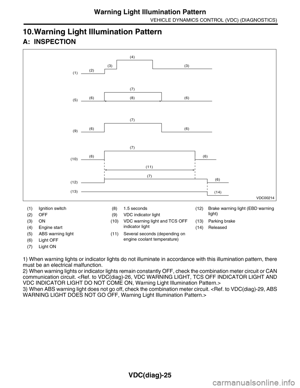
10.Warning Light Illumination Pattern
A: INSPECTION
1) When warning lights or indicator lights do not illuminate in accordance with this illumination pattern, there
must be an electrical malfunction.
2) When warning lights or indicator lights remain constantly OFF, check the combination meter circuit or CAN
communication circuit.
3) When ABS warning light does not go off, check the combination meter circuit.
(1) Ignition switch (8) 1.5 seconds (12) Brake warning light (EBD warning
light)(2) OFF (9) VDC indicator light
(3) ON (10) VDC warning light and TCS OFF
indicator light
(13) Parking brake
(4) Engine start (14) Released
(5) ABS warning light (11) Several seconds (depending on
engine coolant temperature)(6) Light OFF
(7) Light ON
VDC00214
(2)
(6) (6)
(7)
(6) (6)
(7)
(8)
(6) (6)
(7)
(11)
(3) (3)
(4)
(1)
(5)
(9)
(10)
(6)(7)
(12)
(14)(13)