2009 SUBARU TRIBECA coolant temperature
[x] Cancel search: coolant temperaturePage 1018 of 2453
VDC(diag)-26
Warning Light Illumination Pattern
VEHICLE DYNAMICS CONTROL (VDC) (DIAGNOSTICS)
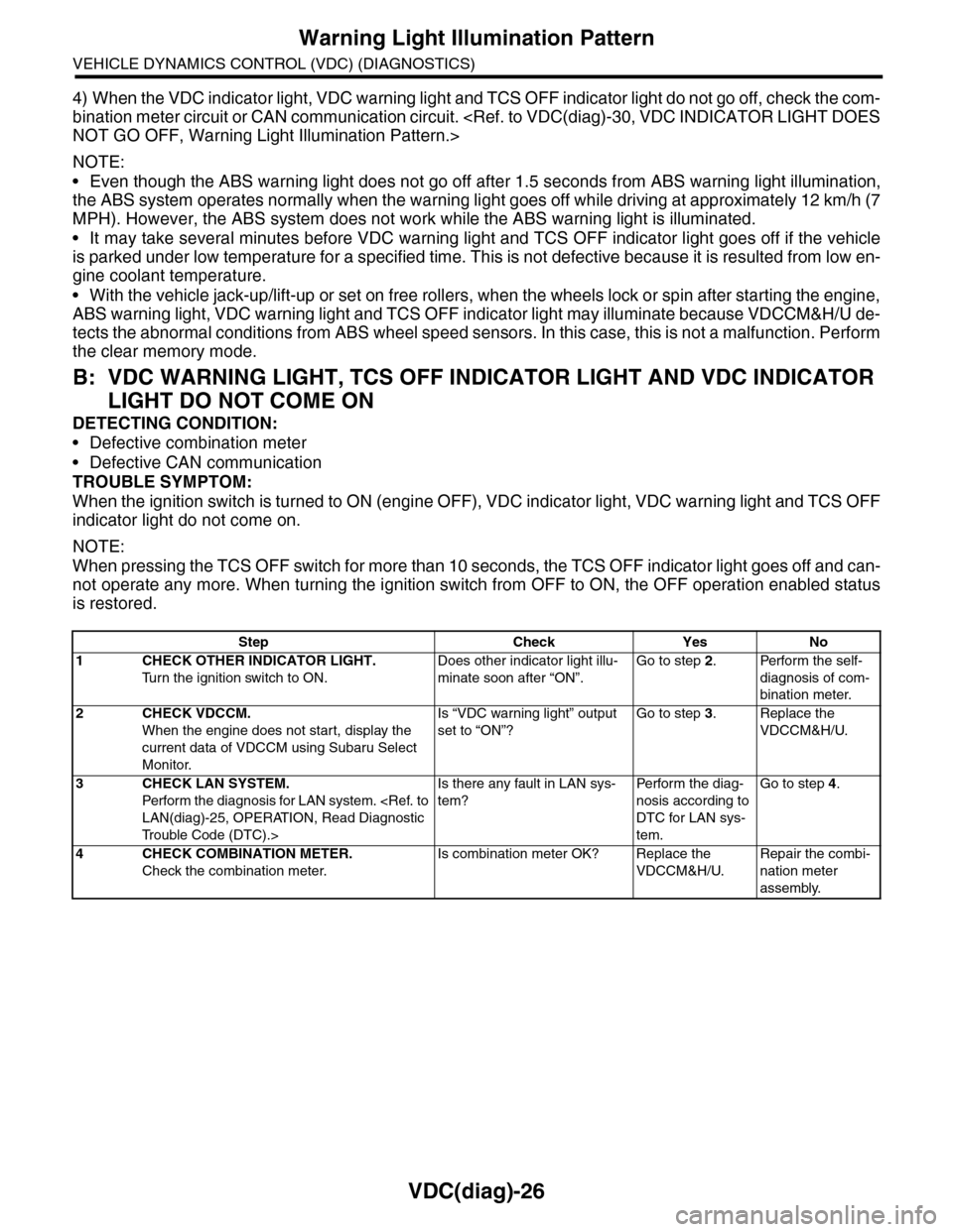
4) When the VDC indicator light, VDC warning light and TCS OFF indicator light do not go off, check the com-
bination meter circuit or CAN communication circuit.
NOTE:
•Even though the ABS warning light does not go off after 1.5 seconds from ABS warning light illumination,
the ABS system operates normally when the warning light goes off while driving at approximately 12 km/h (7
MPH). However, the ABS system does not work while the ABS warning light is illuminated.
•It may take several minutes before VDC warning light and TCS OFF indicator light goes off if the vehicle
is parked under low temperature for a specified time. This is not defective because it is resulted from low en-
gine coolant temperature.
•With the vehicle jack-up/lift-up or set on free rollers, when the wheels lock or spin after starting the engine,
ABS warning light, VDC warning light and TCS OFF indicator light may illuminate because VDCCM&H/U de-
tects the abnormal conditions from ABS wheel speed sensors. In this case, this is not a malfunction. Perform
the clear memory mode.
B: VDC WARNING LIGHT, TCS OFF INDICATOR LIGHT AND VDC INDICATOR
LIGHT DO NOT COME ON
DETECTING CONDITION:
•Defective combination meter
•Defective CAN communication
TROUBLE SYMPTOM:
When the ignition switch is turned to ON (engine OFF), VDC indicator light, VDC warning light and TCS OFF
indicator light do not come on.
NOTE:
When pressing the TCS OFF switch for more than 10 seconds, the TCS OFF indicator light goes off and can-
not operate any more. When turning the ignition switch from OFF to ON, the OFF operation enabled status
is restored.
Step Check Yes No
1CHECK OTHER INDICATOR LIGHT.
Tu r n t h e i g n i t i o n s w i t c h t o O N .
Does other indicator light illu-
minate soon after “ON”.
Go to step 2.Perform the self-
diagnosis of com-
bination meter.
2CHECK VDCCM.
When the engine does not start, display the
current data of VDCCM using Subaru Select
Monitor.
Is “VDC warning light” output
set to “ON”?
Go to step 3.Replace the
VDCCM&H/U.
3CHECK LAN SYSTEM.
Perfor m the diagnosis for LAN system.
Tr o u b l e C o d e ( D T C ) . >
Is there any fault in LAN sys-
tem?
Pe r for m t h e d ia g -
nosis according to
DTC for LAN sys-
tem.
Go to step 4.
4CHECK COMBINATION METER.
Check the combination meter.
Is combination meter OK? Replace the
VDCCM&H/U.
Repair the combi-
nation meter
assembly.
Page 1121 of 2453
CO(H6DO)-2
General Description
COOLING
1. General Description
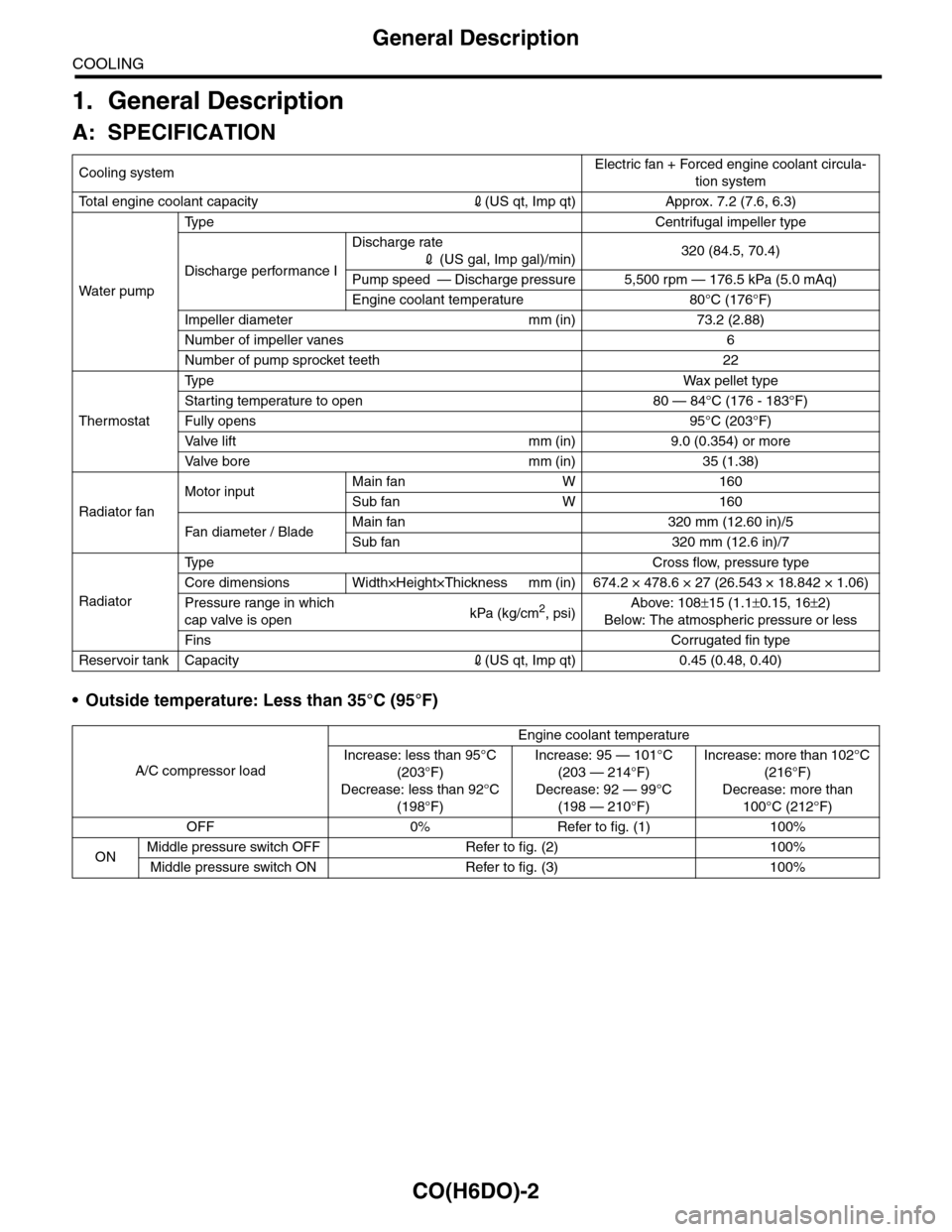
A: SPECIFICATION
•Outside temperature: Less than 35°C (95°F)
Cooling systemElectric fan + Forced engine coolant circula-
tion system
To t a l e n g i n e c o o l a n t c a p a c i t y2(US qt, Imp qt) Approx. 7.2 (7.6, 6.3)
Wa t er p u mp
Ty p e C e n t r i f u g a l i m p e l l e r t y p e
Discharge performance I
Discharge rate
2 (US gal, Imp gal)/min)320 (84.5, 70.4)
Pump speed — Discharge pressure 5,500 rpm — 176.5 kPa (5.0 mAq)
Engine coolant temperature 80°C (176°F)
Impeller diameter mm (in) 73.2 (2.88)
Number of impeller vanes 6
Number of pump sprocket teeth 22
Thermostat
Ty p eWa x p el l et t yp e
Starting temperature to open 80 — 84°C (176 - 183°F)
Fully opens 95°C (203°F)
Va l ve l i f t m m ( i n ) 9 . 0 ( 0 . 3 5 4 ) o r m o r e
Va l ve b o r e m m ( i n ) 3 5 ( 1 . 3 8 )
Radiator fan
Motor inputMain fan W 160
Sub fan W 160
Fan di a me t er / B la deMain fan 320 mm (12.60 in)/5
Sub fan 320 mm (12.6 in)/7
Radiator
Ty p e C r o s s f l o w , p r e s s u r e t y p e
Core dimensions Width×Height×Thickness mm (in) 674.2 × 478.6 × 27 (26.543 × 18.842 × 1.06)
Pressure range in which
cap valve is openkPa (kg/cm2, psi)Above: 108±15 (1.1±0.15, 16±2)
Below: The atmospheric pressure or less
FinsCorrugated fin type
Reservoir tank Capacity2(US qt, Imp qt) 0.45 (0.48, 0.40)
A/C compressor load
Engine coolant temperature
Increase: less than 95°C
(203°F)
Decrease: less than 92°C
(198°F)
Increase: 95 — 101°C
(203 — 214°F)
Decrease: 92 — 99°C
(198 — 210°F)
Increase: more than 102°C
(216°F)
Decrease: more than
100°C (212°F)
OFF 0% Refer to fig. (1) 100%
ONMiddle pressure switch OFF Refer to fig. (2) 100%
Middle pressure switch ON Refer to fig. (3) 100%
Page 1122 of 2453
CO(H6DO)-3
General Description
COOLING
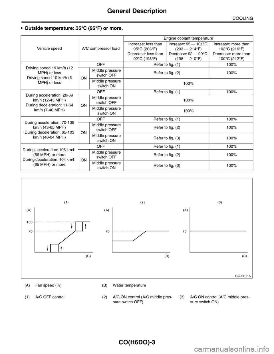
•Outside temperature: 35°C (95°F) or more.
Ve h i c l e s p e e d A / C c o m p r e s s o r l o a d
Engine coolant temperature
Increase: less than
95°C (203°F)
Decrease: less than
92°C (198°F)
Increase: 95 — 101°C
(203 — 214°F)
Decrease: 92 — 99°C
(198 — 210°F)
Increase: more than
102°C (216°F)
Decrease: more than
100°C (212°F)
Driving speed 19 km/h (12
MPH) or less
Driving speed 10 km/h (6
MPH) or less
OFF Refer to fig. (1) 100%
ON
Middle pressure
switch OFFRefer to fig. (2) 100%
Middle pressure
switch ON100%
During acceleration: 20-69
km/h (12-43 MPH)
During deceleration: 11-64
km/h (7-40 MPH)
OFF Refer to fig. (1) 100%
ON
Middle pressure
switch OFF100%
Middle pressure
switch ON100%
During acceleration: 70-105
km/h (43-65 MPH)
During deceleration: 65-103
km/h (40-64 MPH)
OFF Refer to fig. (1) 100%
ON
Middle pressure
switch OFFRefer to fig. (2) 100%
Middle pressure
switch ONRefer to fig. (3) 100%
During acceleration: 106 km/h
(66 MPH) or more
During deceleration: 104 km/h
(65 MPH) or more
OFF Refer to fig. (1) 100%
ON
Middle pressure
switch OFFRefer to fig. (2) 100%
Middle pressure
switch ONRefer to fig. (3) 100%
(A) Fan speed (%) (B) Water temperature
(1) A/C OFF control (2) A/C ON control (A/C middle pres-
sure switch OFF)
(3) A/C ON control (A/C middle pres-
sure switch ON)
CO-02115
100
(1)
70
(A)
(B)
(2)
70
(A)
(B)
(3)
70
(A)
(B)
Page 1127 of 2453
CO(H6DO)-8
Radiator Fan System
COOLING
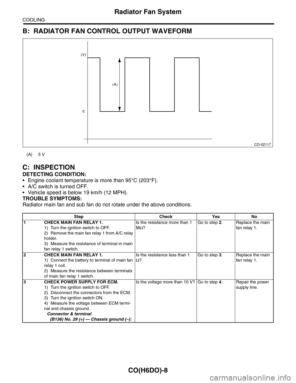
B: RADIATOR FAN CONTROL OUTPUT WAVEFORM
C: INSPECTION
DETECTING CONDITION:
•Engine coolant temperature is more than 95°C (203°F).
•A/C switch is turned OFF.
•Vehicle speed is below 19 km/h (12 MPH).
TROUBLE SYMPTOMS:
Radiator main fan and sub fan do not rotate under the above conditions.
(A) 5 V
Step Check Yes No
1CHECK MAIN FAN RELAY 1.
1) Turn the ignition switch to OFF.
2) Remove the main fan relay 1 from A/C relay
holder.
3) Measure the resistance of terminal in main
fan relay 1 switch.
Is the resistance more than 1
MΩ?
Go to step 2.Replace the main
fan relay 1.
2CHECK MAIN FAN RELAY 1.
1) Connect the battery to terminal of main fan
relay 1 coil.
2) Measure the resistance between terminals
of main fan relay 1 switch.
Is the resistance less than 1
Ω?
Go to step 3.Replace the main
fan relay 1.
3CHECK POWER SUPPLY FOR ECM.
1) Turn the ignition switch to OFF.
2) Disconnect the connectors from the ECM.
3) Turn the ignition switch ON.
4) Measure the voltage between ECM termi-
nal and chassis ground.
Connector & terminal
(B136) No. 29 (+) — Chassis ground (–):
Is the voltage more than 10 V? Go to step 4.Repair the power
supply line.
CO-02117
(V)
0
(A)
Page 1130 of 2453
CO(H6DO)-11
Engine Coolant
COOLING
11) Wait for one minute after the engine stops,
open the radiator cap. If the engine coolant level
drops, add engine coolant into radiator up to the fill-
er neck position.
12) Perform the procedures 10) and 11) again.
13) Attach the radiator cap and reservoir tank cap
properly.
14) Start the engine and operate the heater at max-
imum hot position and the blower speed setting to
“LO.”
15) Run the engine at 2,000 rpm or less until radia-
tor fan starts and stops.
NOTE:
•Be careful with the engine coolant temperature
gauge to prevent overheating.
•If the radiator hose becomes harden with the
pressure of engine coolant, air bleeding operation
seems to be almost completed.
16) Stop the engine and wait until the engine cool-
ant temperature lowers to 30°C (86°F).
17) Open the radiator cap. If the engine coolant lev-
el drops, add engine coolant into radiator up to the
filler neck position and reservoir tank to the “FULL”
level.
18) Attach the radiator cap and reservoir tank cap
properly.
19) Set the heater setting to maximum hot position
and the blower speed setting to “LO” and start the
engine. Perform racing at less than 3,000 rpm. If
the flowing sound is heard at this time, perform the
procedures from 15) again.
B: INSPECTION
1. RELATIONSHIP OF SUBARU COOLANT
CONCENTRATION AND FREEZING TEM-
PERATURE
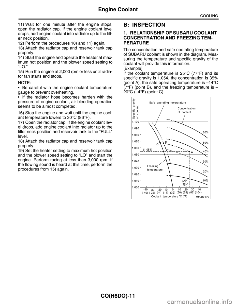
The concentration and safe operating temperature
of SUBARU coolant is shown in the diagram. Mea-
suring the temperature and specific gravity of the
coolant will provide this information.
[Example]
If the coolant temperature is 25°C (77°F) and its
specific gravity is 1.054, the concentration is 35%
(point A), the safe operating temperature is –14°C
(7°F) (point B), and the freezing temperature is –
20°C (–4°F) (point C).
CO-02172
60%
(1.054)
1.000
1.010
1.020
1.030
1.040
1.050
1.060
1.070
1.080
1.090
1.100
Safe operating temperature
Freezingtemperature
Concentrationof coolant
Specific gravityof coolant
Coolant temperature
B
A
C
-40(-40) (-22)(-4)(14)(32)(50) (68) (86)
( F)
(104)-30-20 -10010203040
(77 F)
50%
40%
30%
20%
25 C
10%
C
Page 1131 of 2453
CO(H6DO)-12
Engine Coolant
COOLING
2. PROCEDURE TO ADJUST THE CON-
CENTRATION OF THE COOLANT
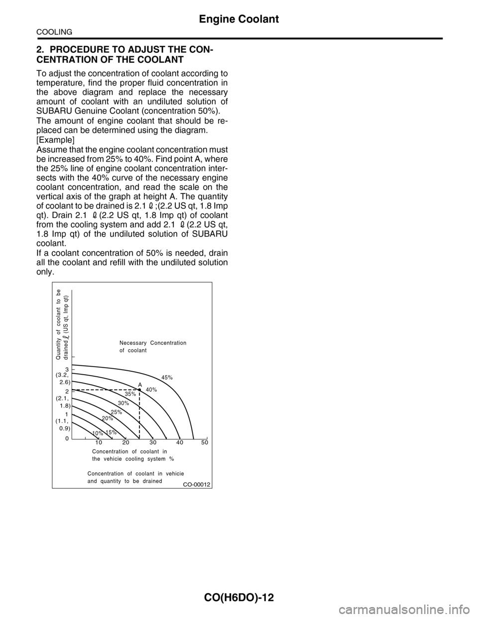
To adjust the concentration of coolant according to
temperature, find the proper fluid concentration in
the above diagram and replace the necessary
amount of coolant with an undiluted solution of
SUBARU Genuine Coolant (concentration 50%).
The amount of engine coolant that should be re-
placed can be determined using the diagram.
[Example]
Assume that the engine coolant concentration must
be increased from 25% to 40%. Find point A, where
the 25% line of engine coolant concentration inter-
sects with the 40% curve of the necessary engine
coolant concentration, and read the scale on the
vertical axis of the graph at height A. The quantity
of coolant to be drained is 2.12;(2.2 US qt, 1.8 Imp
qt). Drain 2.1 2(2.2 US qt, 1.8 Imp qt) of coolant
from the cooling system and add 2.1 2(2.2 US qt,
1.8 Imp qt) of the undiluted solution of SUBARU
coolant.
If a coolant concentration of 50% is needed, drain
all the coolant and refill with the undiluted solution
only.
CO-00012
100
1
2
3
(1.1, 0.9)
(2.1, 1.8)
(3.2, 2.6)
10%15%
25%20%
30%
35%40%
45%A
20 30 40 50
Concentration of coolant in vehicieand quantity to be drained
Quantity of coolant to bedrained (US qt, Imp qt)
Necessary Concentrationof coolant
Concentration of coolant inthe vehicie cooling system %
Page 1133 of 2453
CO(H6DO)-14
Thermostat
COOLING
5. Thermostat
A: REMOVAL
1) Set the vehicle on a lift.
2) Lift-up the vehicle.
3) Remove the under cover.
4) Drain engine coolant completely.
5) Disconnect the radiator hose from thermostat
cover.
6) Remove the thermostat cover, and then remove
the thermostat.
B: INSTALLATION
1) Install a gasket to thermostat.
NOTE:
Use a new gasket.
2) Install the thermostat and thermostat cover.
NOTE:
The thermostat must be installed with the jiggle pin
facing to the up side.
Tightening torque:
6.4 N·m (0.65 kgf-m, 4.7 ft-lb)
3) Connect the radiator hose to thermostat cover.
4) Install the under cover.
5) Lower the vehicle.
6) Fill engine coolant.
MENT, Engine Coolant.>
C: INSPECTION
Replace the thermostat if the valve does not close
completely at an ambient temperature or if the fol-
lowing test shows unsatisfactory results.
•Inspection method
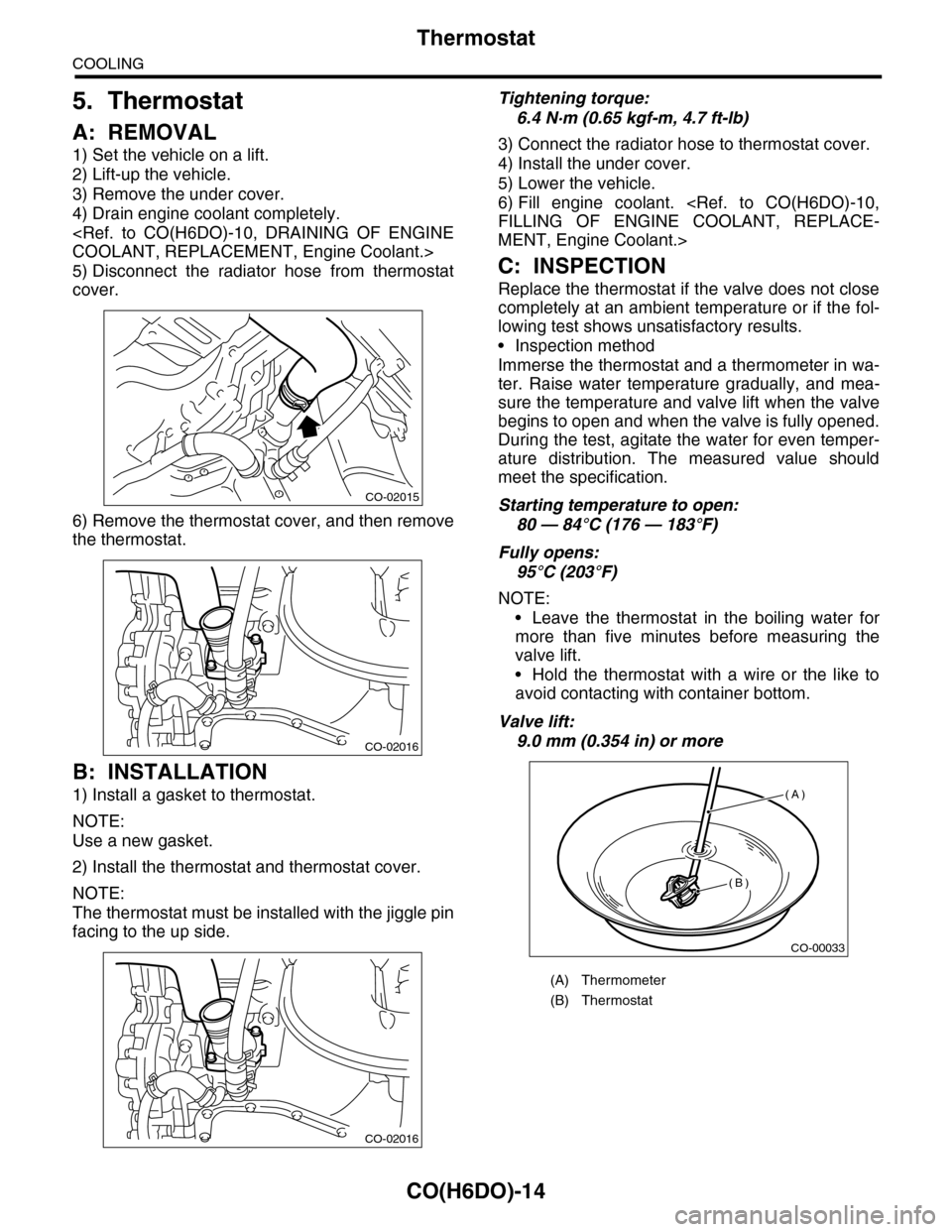
Immerse the thermostat and a thermometer in wa-
ter. Raise water temperature gradually, and mea-
sure the temperature and valve lift when the valve
begins to open and when the valve is fully opened.
During the test, agitate the water for even temper-
ature distribution. The measured value should
meet the specification.
Starting temperature to open:
80 — 84°C (176 — 183°F)
Fully opens:
95°C (203°F)
NOTE:
•Leave the thermostat in the boiling water for
more than five minutes before measuring the
valve lift.
•Hold the thermostat with a wire or the like to
avoid contacting with container bottom.
Valve lift:
9.0 mm (0.354 in) or more
CO-02015
CO-02016
CO-02016
(A) Thermometer
(B) Thermostat
CO-00033
(A)
(B)
Page 1149 of 2453
CO(H6DO)-30
Engine Cooling System Trouble in General
COOLING
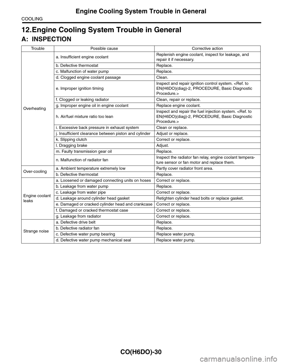
12.Engine Cooling System Trouble in General
A: INSPECTION
Tr o u b l e P o s s i b l e c a u s e C o r r e c t i v e a c t i o n
Overheating
a. Insufficient engine coolantReplenish engine coolant, inspect for leakage, and
repair it if necessary.
b. De fe c ti ve t he r mo st a t Rep la c e.
c. Malfunction of water pump Replace.
d. Clogged engine coolant passage Clean.
e. Improper ignition timing
Inspect and repair ignition control system.
Procedure.>
f. Clogged or leaking radiator Clean, repair or replace.
g. Improper engine oil in engine coolant Replace engine coolant.
h. Air/fuel mixture ratio too lean
Inspect and repair the fuel injection system.
Procedure.>
i. Excessive back pressure in exhaust system Clean or replace.
j. Insufficient clearance between piston and cylinder Adjust or replace.
k. Slipping clutch Correct or replace.
l. Dragging brake Adjust.
m. Faulty transmission gear oil Replace.
n. Malfunction of radiator fanInspect the radiator fan relay, engine coolant tempera-
ture sensor or fan motor and replace them.
Over-coolinga. Ambient temperature extremely low Partly cover radiator front area.
b. De fe c ti ve t he r mo st a t Rep la c e.
Engine coolant
leaks
a. Loosened or damaged connecting units on hoses Correct or replace.
b. L ea k ag e f r o m wat e r pu mp Rep la c e.
c. Leakage from water pipe Correct or replace.
d. Leakage around cylinder head gasket Retighten cylinder head bolts or replace gasket.
e. Damaged or cracked cylinder head and crankcase Correct or replace.
f. Damaged or cracked ther mostat case Correct or replace.
g. Leakage from radiator Correct or replace.
Strange noise
a. Defective drive belt Replace.
b. De fe c ti ve ra di a t or fan Rep la c e.
c. Defective water pump bearing Replace water pump.
d. Defective water pump mechanical seal Replace water pump.