2009 SUBARU TRIBECA Transmission speed sensor
[x] Cancel search: Transmission speed sensorPage 831 of 2453

DS-14
Front Axle
DRIVE SHAFT SYSTEM
11) Remove the front arm ball joint from the front
housing.
12) Remove the PTJ from transmission.
13) Remove the front drive shaft assembly from the
hub. If it is hard to remove, use the ST.
ST1 926470000 AXLE SHAFT PULLER
ST2 28099PA110 AXLE SHAFT PULLER
PLATE
14) After scribing an alignment mark on the camber
adjusting bolt head, remove the bolts which con-
nect the front housing and strut, and disconnect the
front housing from the strut.
15) Remove the front axle.
B: INSTALLATION
1) Align the alignment mark on the camber adjust-
ing bolt head, and affix the front housing and strut
together using a new selflocking nut.
Tightening torque:
175 N·m (17.9 kgf-m, 129 ft-lb)
2) Install the front drive shaft.
3) Install the front arm ball joint to the front housing.
Tightening torque:
50 N·m (5.1 kgf-m, 36.9 ft-lb)
4) Install the ABS wheel speed sensor on the front
housing.
Tightening torque:
7.5 N·m (0.8 kgf-m, 5.5 ft-lb)
5) Install the disc rotor to hub.
6) Install the disc brake caliper to the front housing.
Tightening torque:
120 N·m (12.2 kgf-m, 88.5 ft-lb)
7) Install the stabilizer link.
8) Connect the tie-rod end ball joint to the knuckle
arm with a castle nut.
Tightening torque:
27.0 N·m (2.75 kgf-m, 19.9 ft-lb)
CAUTION:
When connecting the tie–rod, do not hit the cap
at bottom of tie–rod end with a hammer.
9) Tighten the castle nut to specified torque and
tighten further within 60° until the pin hole is aligned
with the slot in nut. Bend the cotter pin to lock.
FS-00106
DS-00145
ST2
ST1
DS-00356
(A) Cotter pin
(B) Castle nut
(C) Tie–rod
DS-00042
(C)
(B)
(A)
Page 1003 of 2453
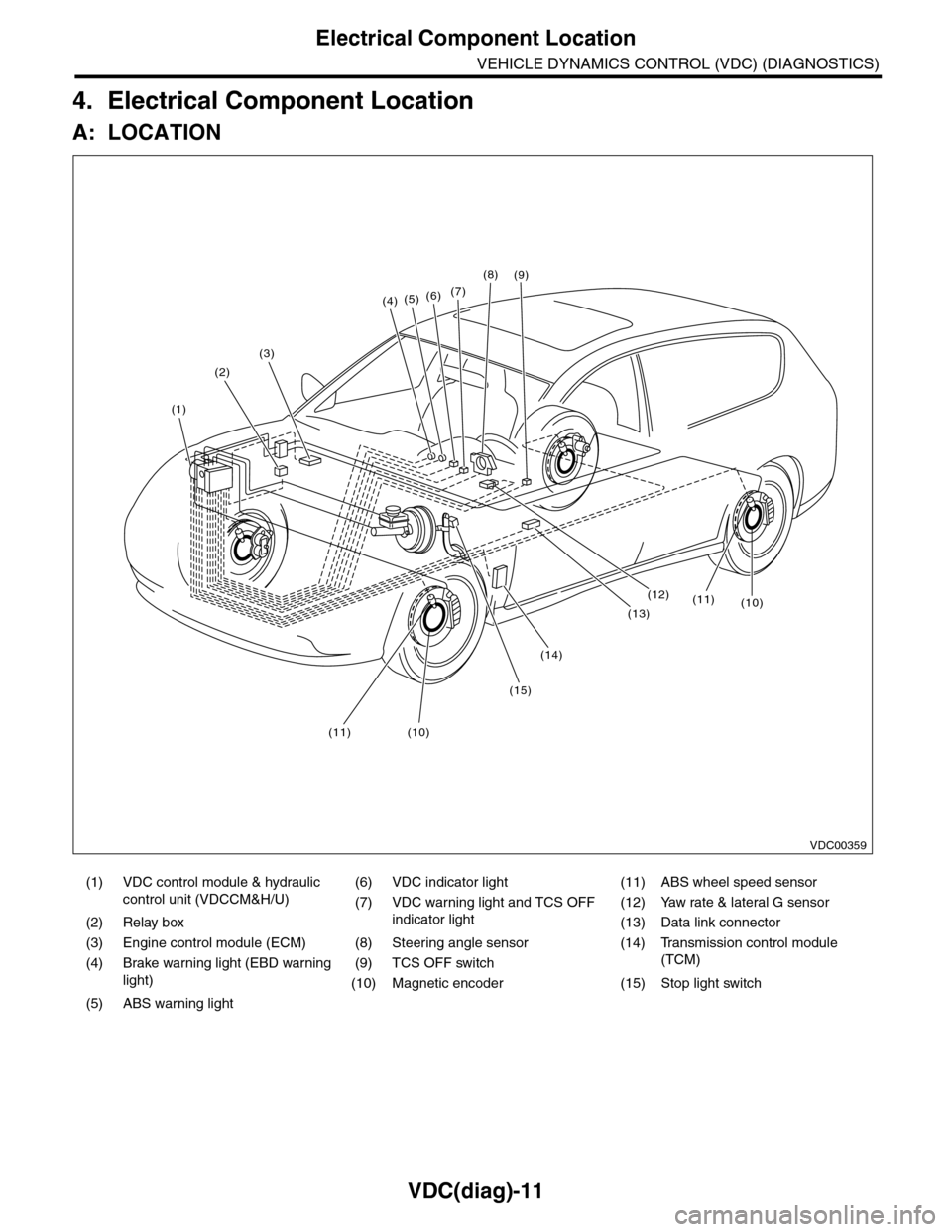
VDC(diag)-11
Electrical Component Location
VEHICLE DYNAMICS CONTROL (VDC) (DIAGNOSTICS)
4. Electrical Component Location
A: LOCATION
(1) VDC control module & hydraulic
control unit (VDCCM&H/U)
(6) VDC indicator light (11) ABS wheel speed sensor
(7) VDC warning light and TCS OFF
indicator light
(12) Yaw rate & lateral G sensor
(2) Relay box (13) Data link connector
(3) Engine control module (ECM) (8) Steering angle sensor (14) Transmission control module
(TCM)(4) Brake warning light (EBD warning
light)
(9) TCS OFF switch
(10) Magnetic encoder (15) Stop light switch
(5) ABS warning light
(4)(5)(6)(7)
(8)
(1)
(2)
(3)
(15)
(14)
(12)
(13)
(11)(10)
(11)(10)
(9)
VDC00359
Page 1197 of 2453
EN(H6DO)(diag)-36
Inspection Mode
ENGINE (DIAGNOSTICS)
P0340 Camshaft Position Sensor “A” Circuit (Bank 1 or Single Sensor) —
P0345 Camshaft Position Sensor “A” Circuit (Bank 2) —
P0447 Evaporative Emission Control System Vent Control Circuit Open —
P0448 Evaporative Emission Control System Vent Control Circuit Shorted —
P0452 Evaporative Emission Control System Pressure Sensor Low Input —
P0453 Evaporative Emission Control System Pressure Sensor High Input —
P0458 Evaporative Emission Control System Purge Control Valve Circuit Low —
P0462 Fuel Level Sensor Circuit Low Input —
P0463 Fuel Level Sensor Circuit High Input —
P0500 Vehicle Speed Sensor—
P0512 Starter Request Circuit—
P0513 Incorrect Immobilizer Key —
P0519 Idle Control System Malfunction (Fail-Safe) —
P0600 Serial Communication Link —
P0604 Internal Control Module Random Access Memory (RAM) Error —
P0605 Internal Control Module Read Only Memory (ROM) Error —
P0607 Control Module Performance —
P0638 Throttle Actuator Control Range/Performance (Bank 1) —
P0691 Cooling Fan 1 Control Circuit Low —
P0692 Cooling Fan 1 Control Circuit High —
P0700 Transmission Control System (MIL Request) —
P1152 O2 Sensor Circuit Range/Performance (Low) (Bank 1 Sensor 1) —
P1153 O2 Sensor Circuit Range/Performance (High) (Bank 1 Sensor 1) —
P1154 O2 Sensor Circuit Range/Performance (Low) (Bank 2 Sensor 1) —
P1155 O2 Sensor Circuit Range/Performance (High) (Bank 2 Sensor 1) —
P1160 Return Spring Failure—
P1518 Starter Switch Circuit Low Input —
P1560 Back-Up Voltage Circuit Malfunction —
P1570 Antenna—
P1571 Reference Code Incompatibility —
P1572 IMM Circuit Failure (Except Antenna Circuit) —
P1574 Key Communication Failure —
P1576 EGI Control Module EEPROM —
P1577 IMM Control Module EEPROM —
P1578 Meter Failure—
P2088 OCV Solenoid Valve Signal A Circuit Open (Bank 1) —
P2089 OCV Solenoid Valve Signal A Circuit Short (Bank 1) —
P2092 OCV Solenoid Valve Signal A Circuit Open (Bank 2) —
P2093 OCV Solenoid Valve Signal A Circuit Short (Bank 2) —
P2101 Throttle Actuator Control Motor Circuit Range/Performance —
P2102 Throttle Actuator Control Motor Circuit Low —
P2109 Throttle/Pedal Position Sensor A Minimum Stop Performance —
P2122 Throttle/Pedal Position Sensor/Switch “D” Circuit Low Input —
P2123 Throttle/Pedal Position Sensor/Switch “D” Circuit High Input —
P2127 Throttle/Pedal Position Sensor/Switch “E” Circuit Low Input —
P2128 Throttle/Pedal Position Sensor/Switch “E” Circuit High Input —
P2135 Throttle/Pedal Position Sensor/Switch “A”/“B” Voltage Rationality —
P2138 Throttle/Pedal Position Sensor/Switch “D”/“E” Voltage Rationality —
P2227 Barometric Pressure Circuit Range/Performance —
P2228 Barometric Pressure Circuit Low Input —
P2229 Barometric Pressure Circuit High Input —
DTC Item On condition
Page 1618 of 2453
GD(H6DO)-6
List of Diagnostic Trouble Code (DTC)
GENERAL DESCRIPTION
P0457 Evaporative Emission Control Sys-
tem Leak Detected (Fuel Cap
Loose/Off)
Tr o u b l e C o d e ( D T C ) D e t e c t i n g C r i t e r i a . >
P0458 Evaporative Emission Control Sys-
tem Purge Control Valve Circuit
Low
ble Code (DTC) Detecting Criteria.>
P0459 Evaporative Emission Control Sys-
tem Purge Control Valve Circuit
High
Tr o u b l e C o d e ( D T C ) D e t e c t i n g C r i t e r i a . >
P0461 Fuel Level Sensor Circuit Range/
Per fo r m an ce
ria.>
P0462 Fuel Level Sensor Circuit Low
Input
P0463 Fuel Level Sensor Circuit High
Input
P0464 Fuel Level Sensor Circuit Intermit-
tent
P0483 Cooling Fan Rationality Check
P0500 Vehicle Speed Sensor
P0506 Idle Control System RPM Lower
Than Expected
ria.>
P0507 Idle Control System RPM Higher
Than Expected
teria.>
P0512 Starter Request Circuit
P0513 Incorrect Immobilizer Key
P0519 Idle Control System Malfunction
(Fail-Safe)
ria.>
P0600 Serial Communication Link
P0604 Internal Control Module Random
Access Memory (RAM) Error
(DTC) Detecting Criteria.>
P0605 Internal Control Module Read Only
Memory (ROM) Error
Detecting Criteria.>
P0607 Control Module Performance
P0638 Throttle Actuator Control Range/
Per fo r m an ce ( B an k 1 )
Detecting Criteria.>
P0691 Cooling Fan 1 Control Circuit Low
P0692 Cooling Fan 1 Control Circuit High
P0700 Transmission Control System (MIL
Request)
P1152 O2 Sensor Circuit Range/Perfor-
mance (Low) (Bank1 Sensor1)
Detecting Criteria.>
DTC Item Index
Page 2020 of 2453
5AT-4
General Description
AUTOMATIC TRANSMISSION
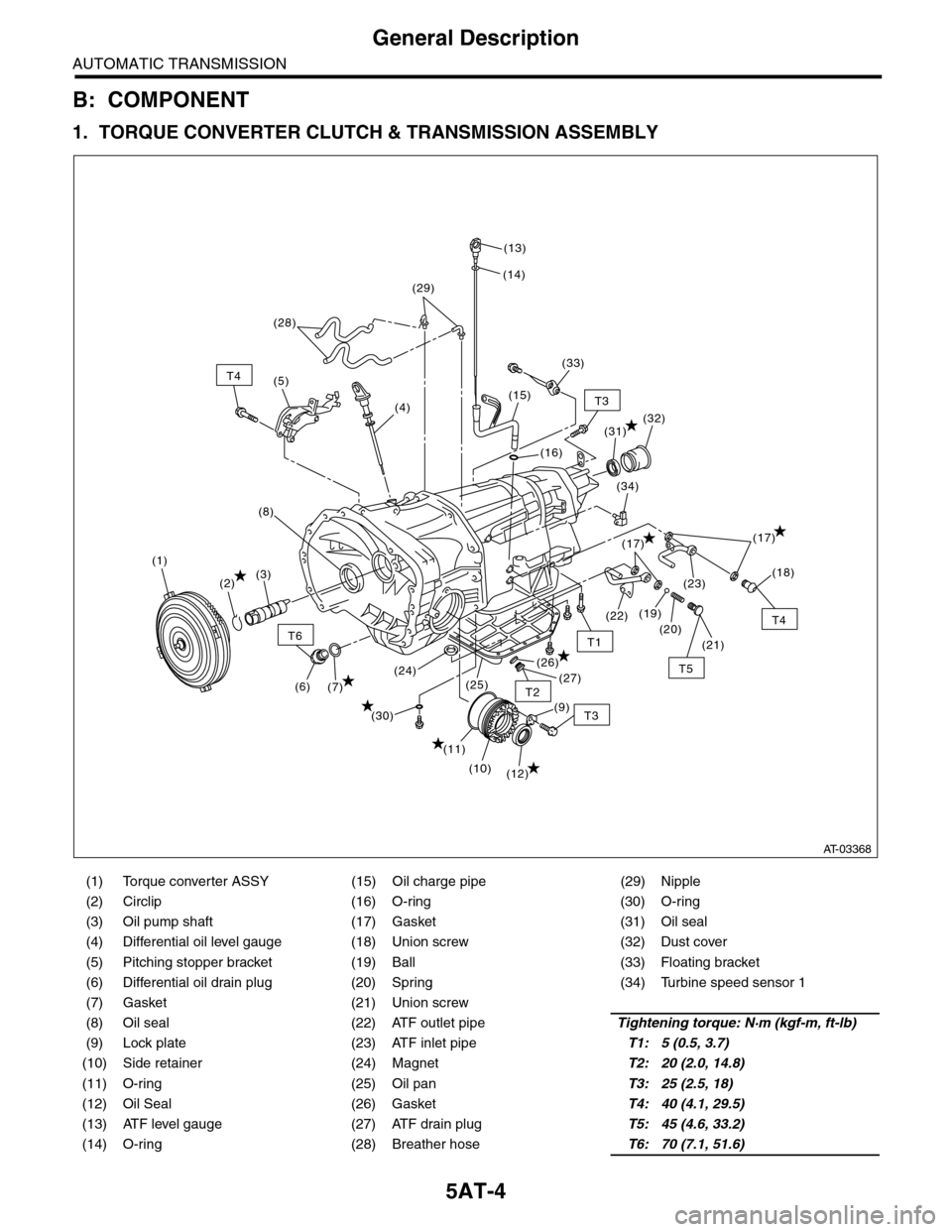
B: COMPONENT
1. TORQUE CONVERTER CLUTCH & TRANSMISSION ASSEMBLY
(1) Torque converter ASSY (15) Oil charge pipe (29) Nipple
(2) Circlip (16) O-ring (30) O-ring
(3) Oil pump shaft (17) Gasket (31) Oil seal
(4) Differential oil level gauge (18) Union screw (32) Dust cover
(5) Pitching stopper bracket (19) Ball (33) Floating bracket
(6) Differential oil drain plug (20) Spring (34) Turbine speed sensor 1
(7) Gasket (21) Union screw
(8) Oil seal (22) ATF outlet pipeTightening torque: N·m (kgf-m, ft-lb)
(9) Lock plate (23) ATF inlet pipeT1: 5 (0.5, 3.7)
(10) Side retainer (24) MagnetT2: 20 (2.0, 14.8)
(11) O-ring (25) Oil panT3: 25 (2.5, 18)
(12) Oil Seal (26) GasketT4: 40 (4.1, 29.5)
(13) ATF level gauge (27) ATF drain plugT5: 45 (4.6, 33.2)
(14) O-ring (28) Breather hoseT6: 70 (7.1, 51.6)
T6
T4
T3
T5
T1
T2
T4
T3
(12)
(11)
(7)(6)
(10)
(21)
(20)
(23)
(26)
(25)(24)(27)
(30)
(19)(22)
(18)
(17)
(34)
(32)
(16)
(15)
(14)
(13)
(28)
(4)
(5)
(1)
(2)(3)
(8)
(29)
(33)
(31)
(9)
(17)
AT-03368
Page 2025 of 2453
5AT-9
General Description
AUTOMATIC TRANSMISSION
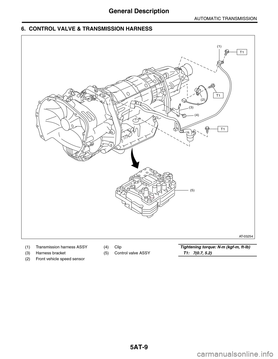
6. CONTROL VALVE & TRANSMISSION HARNESS
(1) Transmission harness ASSY (4) ClipTightening torque: N·m (kgf-m, ft-lb)
(3) Harness bracket (5) Control valve ASSYT1: 7(0.7, 5.2)
(2) Front vehicle speed sensor
(1)
(2)
(3)
(4)
(5)
T1
T1
T1
AT-03254
Page 2051 of 2453
5AT-35
Automatic Transmission Assembly
AUTOMATIC TRANSMISSION
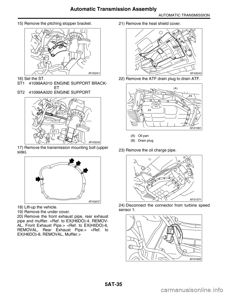
15) Remove the pitching stopper bracket.
16) Set the ST.
ST1 41099AA010 ENGINE SUPPORT BRACK-
ET
ST2 41099AA020 ENGINE SUPPORT
17) Remove the transmission mounting bolt (upper
side).
18) Lift-up the vehicle.
19) Remove the under cover.
20) Remove the front exhaust pipe, rear exhaust
pipe and muffler.
21) Remove the heat shield cover.
22) Remove the ATF drain plug to drain ATF.
23) Remove the oil charge pipe.
24) Disconnect the connector from turbine speed
sensor 1.
AT-03241
AT-03242
ST2
ST1
AT-03237
(A) Oil pan
(B) Drain plug
AT-03243
(A)
AT-01361
(B)
AT-01371
AT-01642
Page 2052 of 2453
5AT-36
Automatic Transmission Assembly
AUTOMATIC TRANSMISSION
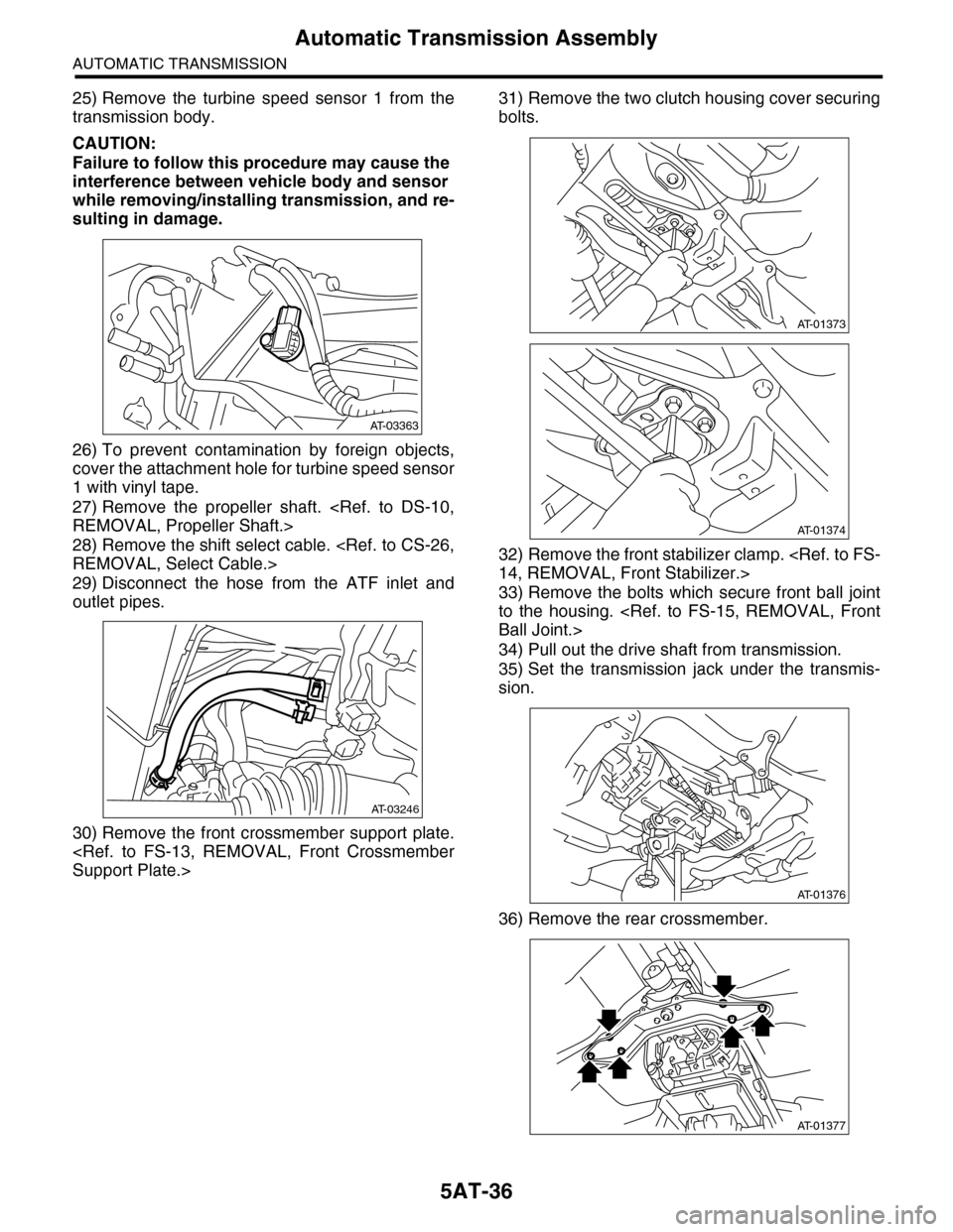
25) Remove the turbine speed sensor 1 from the
transmission body.
CAUTION:
Failure to follow this procedure may cause the
interference between vehicle body and sensor
while removing/installing transmission, and re-
sulting in damage.
26) To prevent contamination by foreign objects,
cover the attachment hole for turbine speed sensor
1 with vinyl tape.
27) Remove the propeller shaft.
28) Remove the shift select cable.
29) Disconnect the hose from the ATF inlet and
outlet pipes.
30) Remove the front crossmember support plate.
31) Remove the two clutch housing cover securing
bolts.
32) Remove the front stabilizer clamp.
33) Remove the bolts which secure front ball joint
to the housing.
34) Pull out the drive shaft from transmission.
35) Set the transmission jack under the transmis-
sion.
36) Remove the rear crossmember.
AT-03363
AT-03246
AT-01373
AT-01374
AT-01376
AT-01377