Page 2079 of 2453
5AT-63
Extension Case
AUTOMATIC TRANSMISSION
24.Extension Case
A: REMOVAL
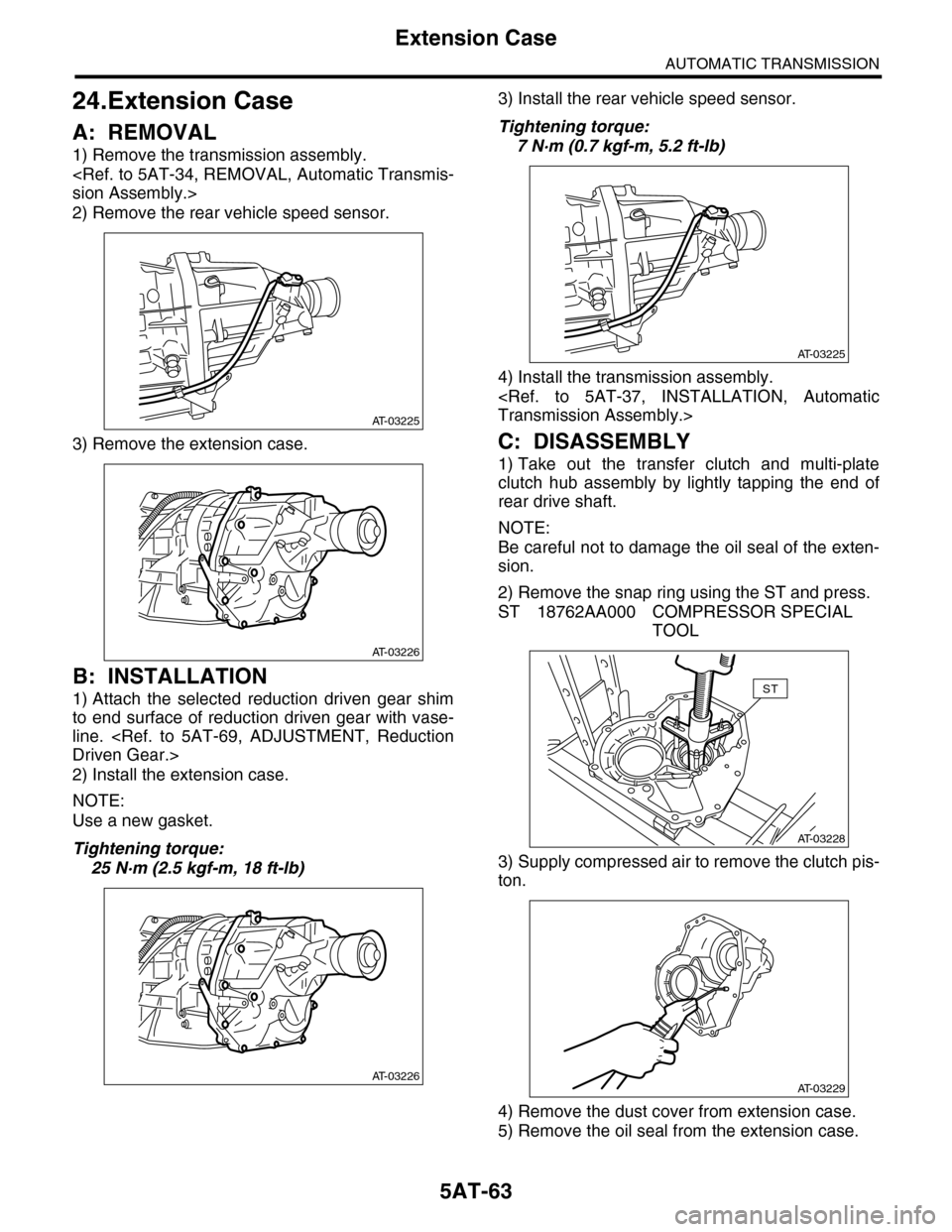
1) Remove the transmission assembly.
sion Assembly.>
2) Remove the rear vehicle speed sensor.
3) Remove the extension case.
B: INSTALLATION
1) Attach the selected reduction driven gear shim
to end surface of reduction driven gear with vase-
line.
Driven Gear.>
2) Install the extension case.
NOTE:
Use a new gasket.
Tightening torque:
25 N·m (2.5 kgf-m, 18 ft-lb)
3) Install the rear vehicle speed sensor.
Tightening torque:
7 N·m (0.7 kgf-m, 5.2 ft-lb)
4) Install the transmission assembly.
Transmission Assembly.>
C: DISASSEMBLY
1) Take out the transfer clutch and multi-plate
clutch hub assembly by lightly tapping the end of
rear drive shaft.
NOTE:
Be careful not to damage the oil seal of the exten-
sion.
2) Remove the snap ring using the ST and press.
ST 18762AA000 COMPRESSOR SPECIAL
TOOL
3) Supply compressed air to remove the clutch pis-
ton.
4) Remove the dust cover from extension case.
5) Remove the oil seal from the extension case.
AT-03225
AT-03226
AT-03226
AT-03225
AT-03228
ST
AT-03229
Page 2083 of 2453
5AT-67
Rear Drive Shaft
AUTOMATIC TRANSMISSION
26.Rear Drive Shaft
A: REMOVAL
1) Remove the transmission assembly from vehicle
body.
Transmission Assembly.>
2) Remove the rear vehicle speed sensor, and then
remove the extension case.
MOVAL, Extension Case.>
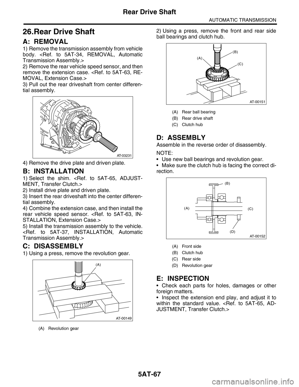
3) Pull out the rear driveshaft from center differen-
tial assembly.
4) Remove the drive plate and driven plate.
B: INSTALLATION
1) Select the shim.
MENT, Transfer Clutch.>
2) Install drive plate and driven plate.
3) Insert the rear driveshaft into the center differen-
tial assembly.
4) Combine the extension case, and then install the
rear vehicle speed sensor.
STALLATION, Extension Case.>
5) Install the transmission assembly to the vehicle.
Transmission Assembly.>
C: DISASSEMBLY
1) Using a press, remove the revolution gear.
2) Using a press, remove the front and rear side
ball bearings and clutch hub.
D: ASSEMBLY
Assemble in the reverse order of disassembly.
NOTE:
•Use new ball bearings and revolution gear.
•Make sure the clutch hub is facing the correct di-
rection.
E: INSPECTION
•Check each parts for holes, damages or other
foreign matters.
•Inspect the extension end play, and adjust it to
within the standard value.
JUSTMENT, Transfer Clutch.>
(A) Revolution gear
AT-03231
AT-00149
(A)
(A) Rear ball bearing
(B) Rear drive shaft
(C) Clutch hub
(A) Front side
(B) Clutch hub
(C) Rear side
(D) Revolution gear
AT-00151
(A)
(B)
(C)
AT-00152
(A)
(B)
(C)
(D)
Page 2084 of 2453
5AT-68
Reduction Driven Gear
AUTOMATIC TRANSMISSION
27.Reduction Driven Gear
A: REMOVAL
1) Remove the transmission assembly from vehicle
body.
Transmission Assembly.>
2) Remove the rear wheel speed sensor, and sep-
arate the extension case from transmission case.
3) Remove the center differential carrier.
5AT-71, REMOVAL, Center Differential Carrier.>
4) Set the range select lever to the “P” range.
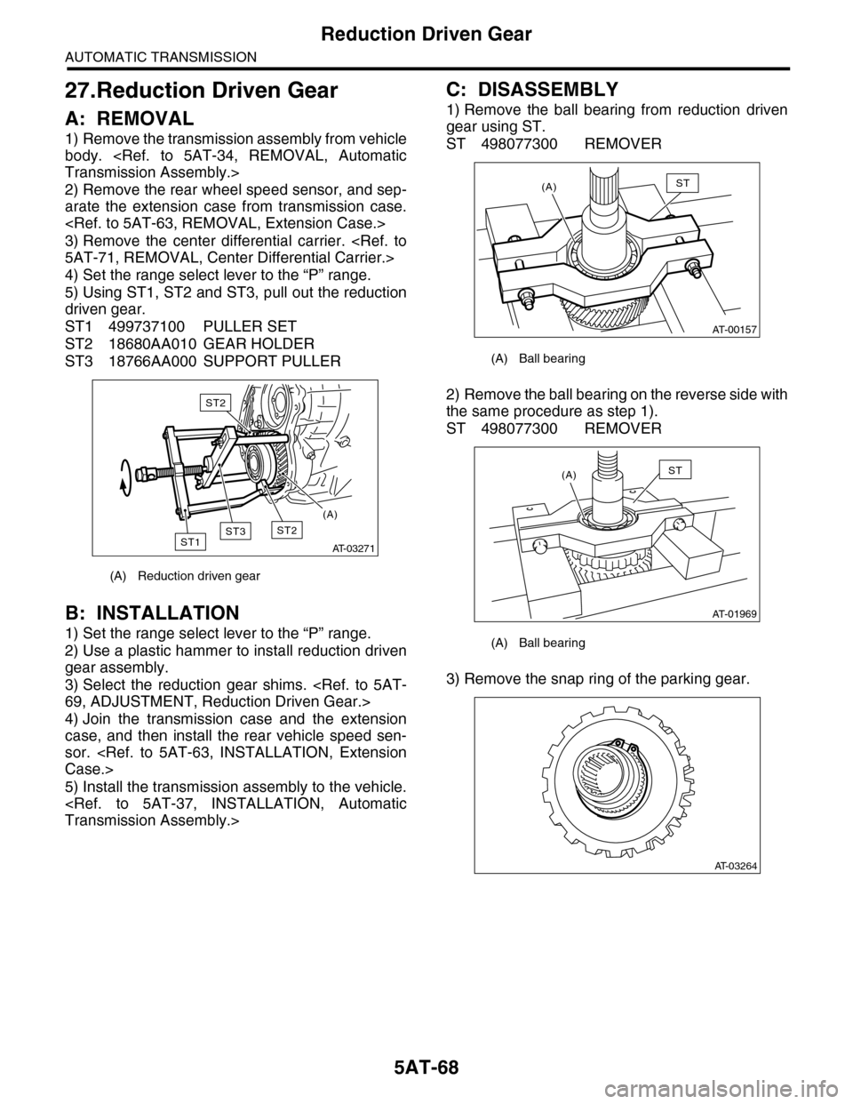
5) Using ST1, ST2 and ST3, pull out the reduction
driven gear.
ST1 499737100 PULLER SET
ST2 18680AA010 GEAR HOLDER
ST3 18766AA000 SUPPORT PULLER
B: INSTALLATION
1) Set the range select lever to the “P” range.
2) Use a plastic hammer to install reduction driven
gear assembly.
3) Select the reduction gear shims.
69, ADJUSTMENT, Reduction Driven Gear.>
4) Join the transmission case and the extension
case, and then install the rear vehicle speed sen-
sor.
Case.>
5) Install the transmission assembly to the vehicle.
Transmission Assembly.>
C: DISASSEMBLY
1) Remove the ball bearing from reduction driven
gear using ST.
ST 498077300 REMOVER
2) Remove the ball bearing on the reverse side with
the same procedure as step 1).
ST 498077300 REMOVER
3) Remove the snap ring of the parking gear.
(A) Reduction driven gear
AT-03271
ST2ST1
ST2
ST3
(A)
(A) Ball bearing
(A) Ball bearing
AT-00157
(A)ST
AT-01969
(A)ST
AT-03264
Page 2087 of 2453
5AT-71
Center Differential Carrier
AUTOMATIC TRANSMISSION
28.Center Differential Carrier
A: REMOVAL
1) Remove the transmission assembly from vehicle
body.
Transmission Assembly.>
2) Remove the rear wheel speed sensor, and sep-
arate the extension case from transmission case.
3) Extract the rear drive shaft.
MOVAL, Rear Drive Shaft.>
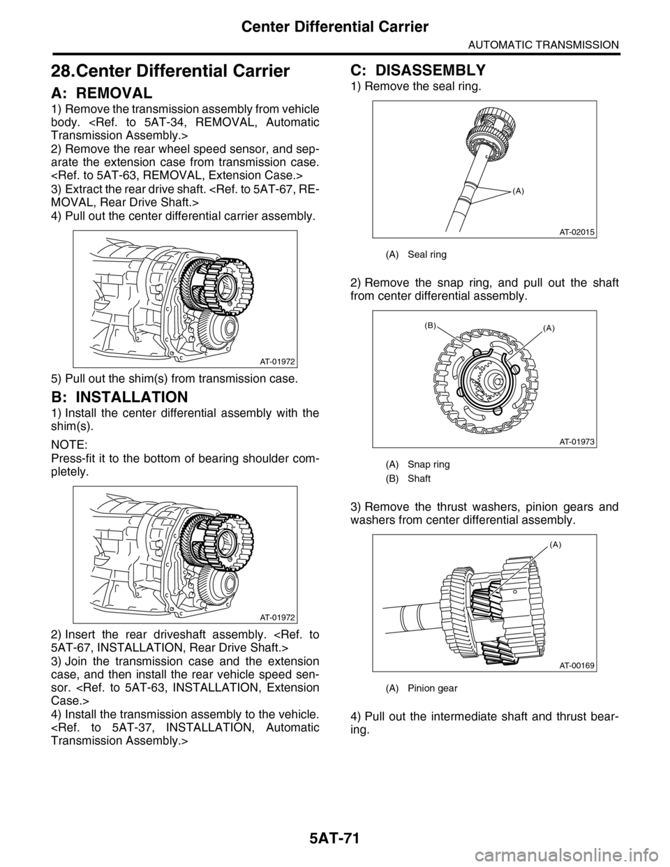
4) Pull out the center differential carrier assembly.
5) Pull out the shim(s) from transmission case.
B: INSTALLATION
1) Install the center differential assembly with the
shim(s).
NOTE:
Press-fit it to the bottom of bearing shoulder com-
pletely.
2) Insert the rear driveshaft assembly.
5AT-67, INSTALLATION, Rear Drive Shaft.>
3) Join the transmission case and the extension
case, and then install the rear vehicle speed sen-
sor.
Case.>
4) Install the transmission assembly to the vehicle.
Transmission Assembly.>
C: DISASSEMBLY
1) Remove the seal ring.
2) Remove the snap ring, and pull out the shaft
from center differential assembly.
3) Remove the thrust washers, pinion gears and
washers from center differential assembly.
4) Pull out the intermediate shaft and thrust bear-
ing.
AT-01972
AT-01972
(A) Seal ring
(A) Snap ring
(B) Shaft
(A) Pinion gear
(A)
AT-02015
AT-01973
(A)(B)
AT-00169
(A)
Page 2089 of 2453
5AT-73
Parking Pawl
AUTOMATIC TRANSMISSION
29.Parking Pawl
A: REMOVAL
1) Remove the transmission assembly from vehicle
body.
Transmission Assembly.>
2) Remove the extension case.
REMOVAL, Extension Case.>
3) Remove the center differential carrier.
5AT-71, REMOVAL, Center Differential Carrier.>
4) Remove the front vehicle speed sensor.
5AT-47, REMOVAL, Front Vehicle Speed Sensor.>
5) Remove the parking support actuator.
6) Remove the parking pawl, parking pawl shaft
and return spring.
B: INSTALLATION
1) Set the transmission to the “N” range.
2) Install the parking pawl, parking pawl shaft and
return spring.
3) Install the parking support actuator.
Tightening torque:
10±2 N·m (1.0±0.2 kgf-m, 7.4±1.5 ft-lb)
4) Using the ST, tighten the bolts which tightened in
step 4) with specified angle.
Tightening angle:
17°±2°
ST 18854AA000 ANGLE GAUGE
NOTE:
Do not use extension as much as possible.
AT-03236
AT-03272
AT-03272
AT-03236
AT-02071ST
AT-02072
ST
Page 2090 of 2453
5AT-74
Parking Pawl
AUTOMATIC TRANSMISSION
5) Make sure that the return spring is sticking out of
the parking pole hole.
6) Install the front vehicle speed sensor.
5AT-47, INSTALLATION, Front Vehicle Speed
Sensor.>
7) Install the center differential carrier.
5AT-71, INSTALLATION, Center Differential Carri-
er.>
8) Install the extension case.
STALLATION, Extension Case.>
9) Install the transmission assembly to the vehicle.
Transmission Assembly.>
C: INSPECTION
Make sure that the tab of parking pawl on reduction
driven gear is not worn or otherwise damaged.
(A) Parking pawl
(B) Return spring
Page 2091 of 2453
5AT-75
Converter Case
AUTOMATIC TRANSMISSION
30.Converter Case
A: REMOVAL
1) Remove the transmission assembly from vehicle
body.
Transmission Assembly.>
2) Remove the torque converter assembly.
5AT-62, REMOVAL, Torque Converter Assembly.>
3) Remove the transmission harness connector
from stay.
4) Remove the turbine speed sensor 1.
5AT-52, REMOVAL, Turbine Speed Sensor 1.>
5) Remove the oil charge pipe.
REMOVAL, Oil Charge Pipe.>
6) Remove the ATF filter inlet and outlet pipes.
Hose.>
7) Remove the converter case attachment bolts.
8) Lay along the transmission body, and then re-
move the oil pan.
9) Remove the three converter case mounting bolts
(TORX®).
ST 18676AA020 TORX® WRENCH
10) Separate the converter case by lightly tapping
with plastic hammer.
11) Remove the differential assembly.
5AT-86, REMOVAL, Front Differential Assembly.>
12) Remove the oil seal from converter case.
B: INSTALLATION
1) Check the appearance of each component and
clean them.
2) Press-fit the oil seal to converter case using ST.
ST 499587100 OIL SEAL INSTALLER
3) Install the differential assembly to the case.
tial Assembly.>
4) Install the right and left side retainers.
5AT-89, ADJUSTMENT, Front Differential Assem-
bly.>
5) Apply proper amount of liquid gasket to the en-
tire matching surface of converter case.
Liquid gasket:
THREE BOND 1215 (Part No. 004403007)
6) Install the converter case assembly without
damaging bushing and oil seal.
Tightening torque:
41 N·m (4.2 kgf-m, 30.4 ft-lb)
AT-01974
AT-01979
ST
AT-01975
Page 2125 of 2453
5AT(diag)-8
Electrical Component Location
AUTOMATIC TRANSMISSION (DIAGNOSTICS)
2. SENSOR
(1) Accelerator pedal position sensor (4) Rear vehicle speed sensor (7) Turbine speed sensor 2
(2) Front vehicle speed sensor (5) Turbine speed sensor 1 (8) ATF temperature sensor 2
(3) Inhibitor switch (6) ATF temperature sensor 1
AT-03280
(3) (6)
(5),(8) (2) (4)
(7)
(1)