2009 SUBARU TRIBECA recommended oil
[x] Cancel search: recommended oilPage 267 of 2453

EI-25
Front Bumper
EXTERIOR/INTERIOR TRIM
3) Deep damage such as a break or hole that requires filling
Much of the peripheral grained surface must be sacrificed for repair. The degree of restoration is not really
worth the expense. (The surface, however, will become almost flush with adjacent areas. )
Recommended repair kit: PP Part Repair Kit (NRM)
Process
No.Process name Job contents
1Bumper removalRemove the bumper as required.
2Removal of partsRemove the parts built into bumper as required.
3Bumper placement
Place the bumper on a paint worktable as
required.
It is recommended to use the paint worktable
conforming to internal shape of bumper.
(1) Bumper
(2) Set bumper section
4Surface prepara-
tion
Remove dust, oil, etc. from areas to be repaired and surrounding areas, using a suitable solvent
(NRM No. 900 Precleno, white gasoline, or alcohol, etc.).
5Cutting
If the damage is a crack or a hole, cut a guide
slit of 20 to 30 mm (0.79 to 1.18 in) in length
along the crack or hole up to the bumper base
surface. Next, use a knife or grinder to carve a
V- s h a p e d g r o o ve i n t h e a r e a f o r r e p a i r.
(1) Paint surface
(2) PP base surface
(3) 20 — 30 mm (0.79 — 1.18 in)
(4) 3 mm (0.12 in)
6Sanding (I) Grind beveled surface with sand paper (#40 — #60) to smooth finish.
7Cleaning Clean the sanded surface with the same solvent as used in Procedure 4.
8Temporary welding
Grind the side just opposite the beveled area with sand paper (#40 — #60) and clean using a
solvent.
Te m p o r a r i l y s p o t - w e l d t h e s i d e , u s i n g P P w e l d i n g r o d a n d h e a t e r g u n .
(1) Welded point (Use heater gun and PP welding rod)
(2) PP base surface
(3) Beveled section
NOTE:•Do not melt welding rod until it flows out. This results in reduced strength.
•Leave the welded spot unattended until it cools completely.
EI-00234(2)
(1)
EI-00235
(4)(2)
(1)(3)
EI-00236
(1)
(2)
(3)
Page 786 of 2453

DI-2
General Description
DIFFERENTIALS
1. General Description
A: SPECIFICATION
1. REAR DIFFERENTIAL
When replacing a rear differential assembly, select the correct one according to the following table.
NOTE:
•Using a different rear differential assembly will cause the drive train and tires to drag or emit abnormal
noise.
•For option code, refer to “ID” section.
2. IDENTIFICATION
Identification label positions are shown in the fol-
lowing figures. For details concerning identification,
refer to the “ID” section.
3. REAR DIFFERENTIAL GEAR OIL
Recommended gear oil:
GL–5 (75W–90)
NOTE:
Each oil manufacturer has its base oil and addi-
tives. Thus, do not mix two or more brands.
4. SERVICE DATA
Rear differential type VA2-type
Identification XX
LSD type—
Ty p e o f g e a r H y p o i d g e a r
Gear ratio (Number of gear teeth) 3.583 (43/12)
Oil capacity 0.82 (0.8 US qt, 0.7 lmp qt)
Rear differential gear oil GL-5
(1) Identification
ID-00114
(1)
(1) Item
(2) Rear differential gear oil
(3) API classification
(4) SAE viscosity No. and applicable temperature
MT-00001
(1)
(4)GL-5(3)
(2)
( C)( F)-30 -26 -15 15
9085W80W75W -90
25 30 -5 0-22-1523328659775
Drive pinion bearing preload Measure with spring measurement. (Mea-
sured from the companion flange bolt)
N (kgf, lb)
12.7 — 32.2 (1.3 — 3.28, 2.9 — 7.24)
Measure with torque wrench
N·m (kgf–m, ft–lb)0.48 — 1.22 (0.045 — 0.124, 0.32 — 0.9)
Hypoid driven gear to drive pinion backlash mm (in) 0.10 — 0.15 (0.0039 — 0.0059)
Page 796 of 2453

DI-12
Differential Gear Oil
DIFFERENTIALS
2. Differential Gear Oil
A: INSPECTION
1) Remove the filler plug, and then check the gear
oil. Replace the gear oil if it is contaminated or de-
teriorated.
2) Check that the gear oil level is up to the bottom
of the filler plug hole. If the level is low, refill up to
the bottom of filler plug.
B: REPLACEMENT
1) Jack–up the vehicle and support it with rigid
racks.
2) Remove the oil drain plug and filler plug, and
drain the gear oil.
CAUTION:
Be careful not to burn your hands, because
gear oil becomes extremely hot after running.
3) Tighten the oil drain plug.
NOTE:
Use a new metal gasket.
Tightening torque:
29 N·m (3.0 kgf-m, 21.7 ft-lb)
4) Fill the differential carrier with gear oil to the bot-
tom of filler plug.
NOTE:
Carefully refill oil while watching the level. Exces-
sive or insufficient oil must be avoided.
Recommended gear oil:
Oil capacity:
0.8 2(0.8 US qt, 0.7 Imp qt)
5) Install the filler plug.
NOTE:
Use a new metal gasket.
Tightening torque:
29 N·m (3.0 kgf-m, 21.7 ft-lb)
(A) Filler plug
(B) Drain plug
(A) Filler plug
(B) Drain plug
(B)DI-00355
(A)
(A)
DI-00357
(B)
(A) Filler plug
(B) Drain plug
(B)DI-00355
(A)
Page 928 of 2453

PS-48
Power Steering Fluid
POWER ASSISTED SYSTEM (POWER STEERING)
9. Power Steering Fluid
A: SPECIFICATION
B: INSPECTION
1) Check the power steering fluid for deterioration
or contamination. If the fluid is highly deteriorated
or contaminated, drain it and refill with new fluid.
2) Check the joints and units for oil leakage. If any
oil leaks are found, repair or replace the applicable
part.
3) Inspect the fluid level of reservoir tank with vehi-
cle on level surface and engine stopped.
If the level is at “MIN. ” point or below, add fluid to
keep the level in the specified range of the indica-
tor. If at “MAX. ” point or above, drain fluid by using
a syringe or the like.
(1) Check at power steering fluid temperature
20°C (68°F); read the fluid level on the “COLD”
side.
(2) Check at power steering fluid temperature
80°C (176°F); read the fluid level on the “HOT”
side.
C: REPLACEMENT
1) Lift-up the vehicle.
2) Remove the crossmember support.
3) Remove the pipe joint in the center of gearbox,
and connect the vinyl hose to the pipe and joint.
Wipe fluid off while turning the steering wheel.
4) Add the specified fluid to reservoir tank at “MAX”
level.
5) Continue to turn the steering wheel slowly from
lock to lock until the bubbles stop appearing on oil
surface while keeping the fluid at the level in the
Step 4).
6) If the steering wheel is turned in a low fluid level
condition, air will be sucked into the pipe. If sucked,
leave it about half an hour and then do the step 5)
again.
7) Start the engine and let it idle.
8) Continue to turn the steering wheel slowly from
lock to lock again until the bubbles stop appearing
on oil surface while keeping the fluid at the level in
Step 4).
Normally bubbles will stop appearing after turning
the steering wheel from lock to lock three times.
9) In case bubbles do not stop appearing in the
tank, leave it about half an hour and then do the
step 4) all over again.
10) Lower the vehicle, and then idle the engine.
11) Continue to turn the steering wheel from lock to
lock until the bubbles stop appearing and change of
the fluid level is within 3 mm (0.12 in).
12) In case the following happens, leave it about
half an hour and then do step 8) to 11) again.
(1) The fluid level changes over 3 mm (0.12 in).
(2) Bubbles remain on the upper surface of the
fluid.
(3) Grinding noise is generated from oil pump.
13) Check the fluid leakage after turning steering
wheel from lock to lock with engine running.
Recommended power steering fluid Manufacturer
AT F D E X R O N I I I o r e q u i v a l e n t
B.P.
CALTEX
CASTROL
MOBIL
SHELL
TEXACO
PS-00745
HOT MAXHOT MAINCOLD MAXCOLD MAIN
Page 1851 of 2453

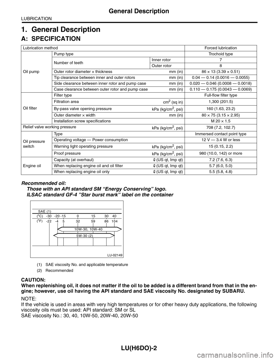
LU(H6DO)-2
General Description
LUBRICATION
1. General Description
A: SPECIFICATION
Recommended oil:
Those with an API standard SM “Energy Conserving” logo.
ILSAC standard GF-4 ”Star burst mark” label on the container
CAUTION:
When replenishing oil, it does not matter if the oil to be added is a different brand from that in the en-
gine; however, use oil having the API standard and SAE viscosity No. designated by SUBARU.
NOTE:
If the vehicle is used in areas with very high temperatures or for other heavy duty applications, the following
viscosity oils must be used: API standard: SM or SL
SAE viscosity No.: 30, 40, 10W-50, 20W-40, 20W-50
Lubrication methodForced lubr ication
Oil pump
Pump typeTr o c h o i d t y p e
Number of teethInner rotor 7
Outer rotor 8
Outer rotor diameter × thickness mm (in) 86 × 13 (3.39 × 0.51)
Tip clearance between inner and outer rotors mm (in) 0.04 — 0.14 (0.0016 — 0.0055)
Side clearance between inner rotor and pump case mm (in) 0.020 — 0.046 (0.0008 — 0.0018)
Case clearance between outer rotor and pump case mm (in) 0.110 — 0.175 (0.0043 — 0.0069)
Oil filter
Filter typeFull-flow filter type
Filtration areacm2 (sq in)1,300 (201.5)
By-pass valve opening pressurekPa (kg/cm2, psi)160 (1.63, 23.2)
Outer diameter × width mm (in) 80 × 75 (3.15 × 2.95)
Installation screw specifications M 20 × 1.5
Relief valve working pressurekPa (kg/cm2, psi)708 (7.2, 102.7)
Oil pressure
switch
Ty p eImmersed contact point type
Operating voltage — Power consumption 12 V — 3.4 W or less
Wa r ni n g l ig h t o p era t i ng pr e ss ur ekPa (kg/cm2, psi)15 (0.15, 2.2)
Proof pressurekPa (kg/cm2, psi)980 (10.0, 142) or more
Engine oil
Capacity (at overhaul)2(US qt, Imp qt) 7.2 (7.6, 6.3)
When replacing engine oil and oil filter2(US qt, Imp qt) 5.7 (6.0, 5.0)
When replacing engine oil only2(US qt, Imp qt) 5.5 (5.8, 4.8)
(1) SAE viscosity No. and applicable temperature
(2) Recommended
LU-02149
( C) -30 -20 -15 0 15 30 40
-22 -4 5 32 59 86 104
SAE (1)
( F)
5W-30 (2)
10W-30, 10W-40
Page 1856 of 2453

LU(H6DO)-7
Engine Oil
LUBRICATION
3. Engine Oil
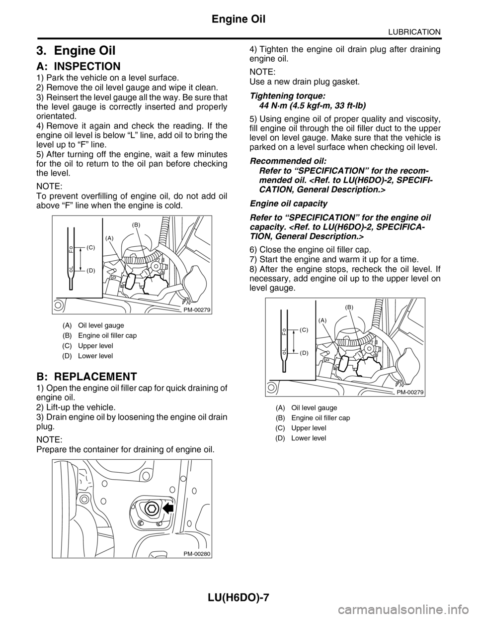
A: INSPECTION
1) Park the vehicle on a level surface.
2) Remove the oil level gauge and wipe it clean.
3) Reinsert the level gauge all the way. Be sure that
the level gauge is correctly inserted and properly
orientated.
4) Remove it again and check the reading. If the
engine oil level is below “L” line, add oil to bring the
level up to “F” line.
5) After turning off the engine, wait a few minutes
for the oil to return to the oil pan before checking
the level.
NOTE:
To prevent overfilling of engine oil, do not add oil
above “F” line when the engine is cold.
B: REPLACEMENT
1) Open the engine oil filler cap for quick draining of
engine oil.
2) Lift-up the vehicle.
3) Drain engine oil by loosening the engine oil drain
plug.
NOTE:
Prepare the container for draining of engine oil.
4) Tighten the engine oil drain plug after draining
engine oil.
NOTE:
Use a new drain plug gasket.
Tightening torque:
44 N·m (4.5 kgf-m, 33 ft-lb)
5) Using engine oil of proper quality and viscosity,
fill engine oil through the oil filler duct to the upper
level on level gauge. Make sure that the vehicle is
parked on a level surface when checking oil level.
Recommended oil:
Refer to “SPECIFICATION” for the recom-
mended oil.
Engine oil capacity
Refer to “SPECIFICATION” for the engine oil
capacity.
6) Close the engine oil filler cap.
7) Start the engine and warm it up for a time.
8) After the engine stops, recheck the oil level. If
necessary, add engine oil up to the upper level on
level gauge.
(A) Oil level gauge
(B) Engine oil filler cap
(C) Upper level
(D) Lower level
PM-00279
(A)
(B)
(C)
(D)
PM-00280
(A) Oil level gauge
(B) Engine oil filler cap
(C) Upper level
(D) Lower level
PM-00279
(A)
(B)
(C)
(D)
Page 1986 of 2453

PM-3
Schedule
PERIODIC MAINTENANCE SERVICES
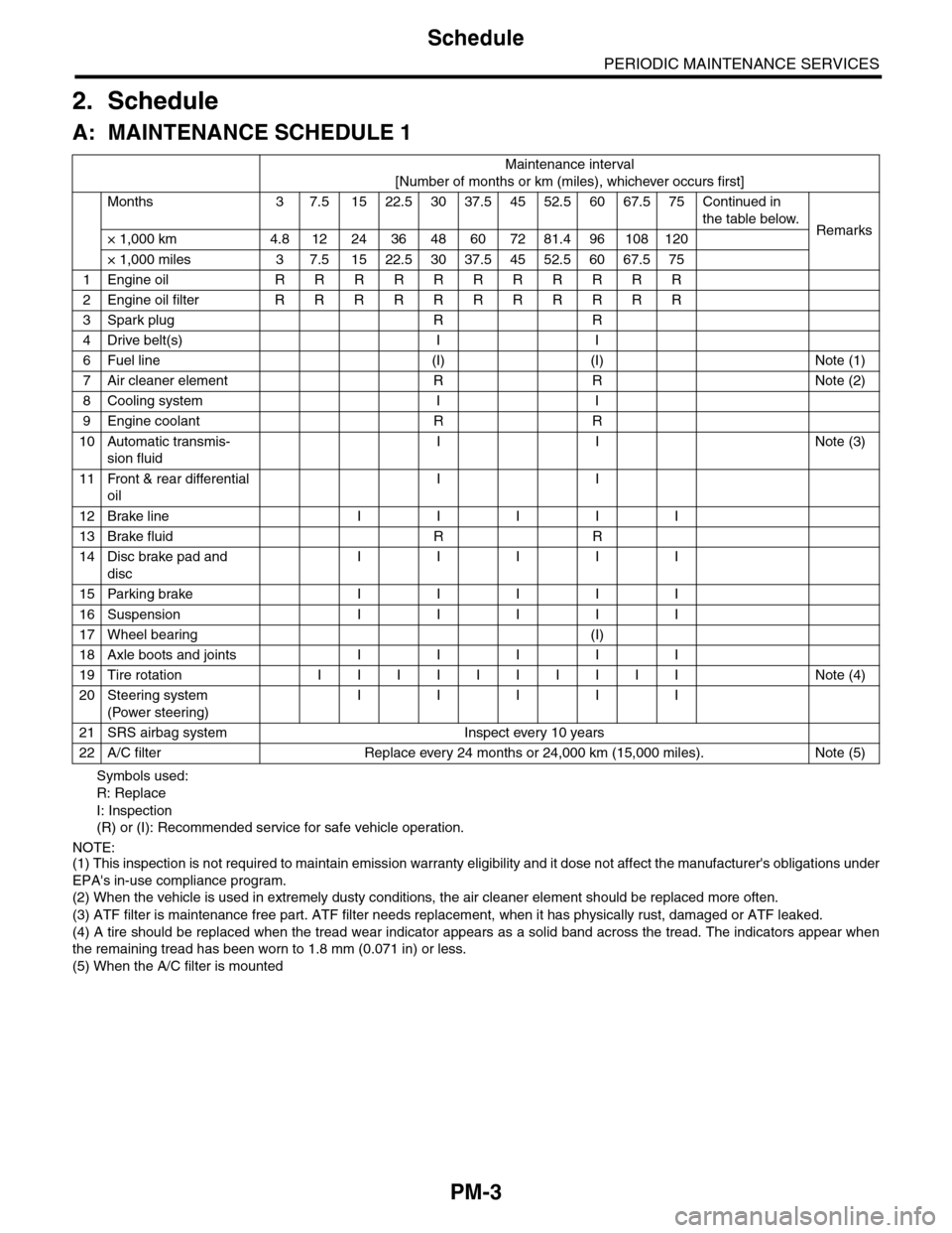
2. Schedule
A: MAINTENANCE SCHEDULE 1
Symbols used:
R: Replace
I: Inspection
(R) or (I): Recommended service for safe vehicle operation.
NOTE:(1) This inspection is not required to maintain emission warranty eligibility and it dose not affect the manufacturer's obligations under
EPA's in-use compliance program.
(2) When the vehicle is used in extremely dusty conditions, the air cleaner element should be replaced more often.
(3) ATF filter is maintenance free part. ATF filter needs replacement, when it has physically rust, damaged or ATF leaked.
(4) A tire should be replaced when the tread wear indicator appears as a solid band across the tread. The indicators appear when
the remaining tread has been worn to 1.8 mm (0.071 in) or less.
(5) When the A/C filter is mounted
Maintenance interval
[Number of months or km (miles), whichever occurs first]
Months 3 7.51522.53037.54552.56067.575Continued in
the table below.Remarks× 1,000 km 4.8 12 24 36 48 60 72 81.4 96 108 120
× 1,000 miles 3 7.5 15 22.5 30 37.5 45 52.5 60 67.5 75
1Engine oil R R R R R R R R R R R
2Engine oil filter R R R R R R R R R R R
3Spark plug R R
4Drive belt(s) I I
6Fuel line (I) (I) Note (1)
7Air cleaner element R R Note (2)
8Cooling system I I
9Engine coolant R R
10 Automatic transmis-
sion fluid
I I Note (3)
11 Front & rear differential
oil
I I
12 Brake line I I I I I
13 Brake fluid R R
14 Disc brake pad and
disc
I I I I I
15 Parking brake I I I I I
16 Suspension I I I I I
17 Wheel bearing (I)
18 Axle boots and joints I I I I I
19 Tire rotation I I I I I I I I I I Note (4)
20 Steering system
(Power steering)
I I I I I
21 SRS airbag system Inspect every 10 years
22 A/C filter Replace every 24 months or 24,000 km (15,000 miles). Note (5)
Page 1987 of 2453

PM-4
Schedule
PERIODIC MAINTENANCE SERVICES
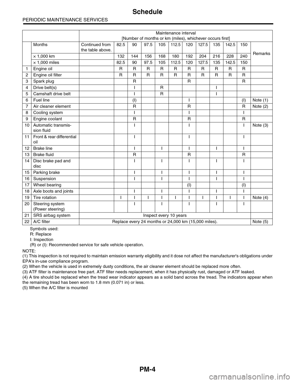
Symbols used:
R: Replace
I: Inspection
(R) or (I): Recommended service for safe vehicle operation.
NOTE:(1) This inspection is not required to maintain emission warranty eligibility and it dose not affect the manufacturer's obligations under
EPA's in-use compliance program.
(2) When the vehicle is used in extremely dusty conditions, the air cleaner element should be replaced more often.
(3) ATF filter is maintenance free part. ATF filter needs replacement, when it has physically rust, damaged or ATF leaked.
(4) A tire should be replaced when the tread wear indicator appears as a solid band across the tread. The indicators appear when
the remaining tread has been worn to 1.8 mm (0.071 in) or less.
(5) When the A/C filter is mounted
Maintenance interval
[Number of months or km (miles), whichever occurs first]
Months Continued from
the table above.
82.5 90 97.5 105112.5120127.5135142.5150
Remarks× 1,000 km 132 144 156 168 180 192 204 216 228 240
× 1,000 miles 82.5 90 97.5 105112.5120127.5135142.5150
1Engine oil R R R R R R R R R R
2Engine oil filter R R R R R R R R R R
3Spark plug R R R
4Drive belt(s) I R I
5Camshaft drive belt I R I
6Fuel line (I) I (I) Note (1)
7Air cleaner element R R R Note (2)
8Cooling system I I I
9Engine coolant R R R
10 Automatic transmis-
sion fluid
I I INote (3)
11 Front & rear differential
oil
I I I
12 Brake line I I I I I
13 Brake fluid R R R
14 Disc brake pad and
disc
I I I I I
15 Parking brake I I I I I
16 Suspension I I I I I
17 Wheel bearing (I) (I)
18 Axle boots and joints I I I I I
19 Tire rotation I I I I I I I I I I Note (4)
20 Steering system
(Power steering)
I I I I I
21 SRS airbag system Inspect every 10 years
22 A/C filter Replace every 24 months or 24,000 km (15,000 miles). Note (5)