Page 1165 of 2453
EN(H6DO)(diag)-4
Check List for Interview
ENGINE (DIAGNOSTICS)
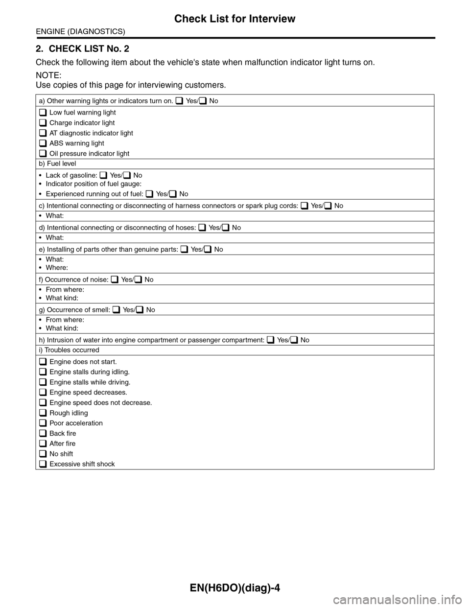
2. CHECK LIST No. 2
Check the following item about the vehicle's state when malfunction indicator light turns on.
NOTE:
Use copies of this page for interviewing customers.
a) Other warning lights or indicators turn on. Yes/ No
Low fuel warning light
Charge indicator light
AT diagnostic indicator light
ABS warning light
Oil pressure indicator light
b) Fuel level
•Lack of gasoline: Yes/ No
•Indicator position of fuel gauge:
•Experienced running out of fuel: Yes/ No
c) Intentional connecting or disconnecting of harness connectors or spark plug cords: Yes/ No
•What:
d) Intentional connecting or disconnecting of hoses: Yes/ No
•What:
e) Installing of parts other than genuine parts: Yes/ No
•What:
•Where:
f) Occurrence of noise: Yes/ No
•From where:
•What kind:
g) Occurrence of smell: Yes/ No
•From where:
•What kind:
h) Intrusion of water into engine compartment or passenger compartment: Yes/ No
i) Troubles occurred
Engine does not start.
Engine stalls during idling.
Engine stalls while driving.
Engine speed decreases.
Engine speed does not decrease.
Rough idling
Poor acceleration
Back fire
After fire
No shift
Excessive shift shock
Page 1225 of 2453
EN(H6DO)(diag)-64
Diagnostics for Engine Starting Failure
ENGINE (DIAGNOSTICS)
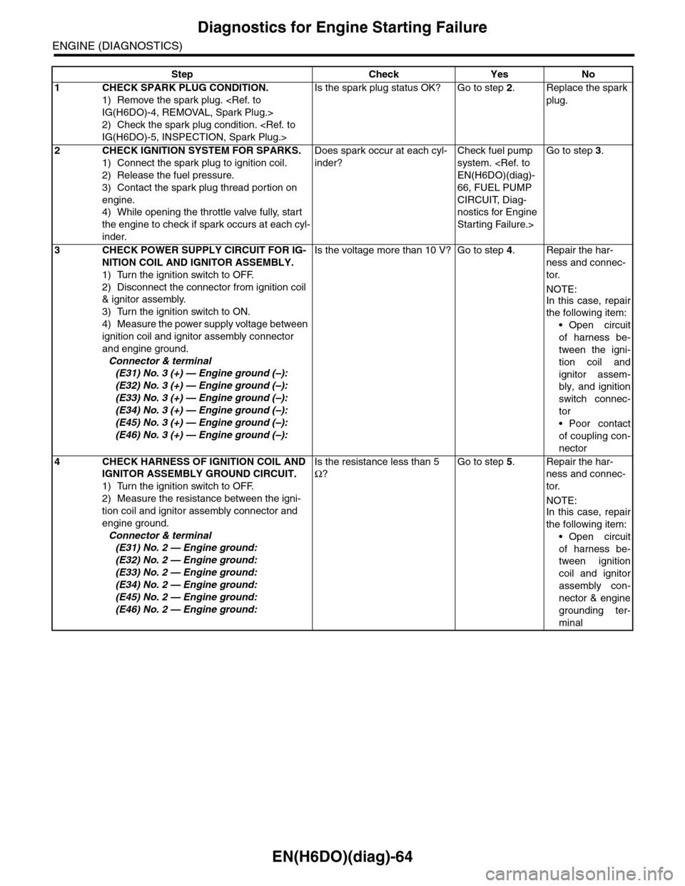
Step Check Yes No
1CHECK SPARK PLUG CONDITION.
1) Remove the spark plug.
IG(H6DO)-4, REMOVAL, Spark Plug.>
2) Check the spark plug condition.
IG(H6DO)-5, INSPECTION, Spark Plug.>
Is the spark plug status OK? Go to step 2.Replace the spark
plug.
2CHECK IGNITION SYSTEM FOR SPARKS.
1) Connect the spark plug to ignition coil.
2) Release the fuel pressure.
3) Contact the spark plug thread portion on
engine.
4) While opening the throttle valve fully, start
the engine to check if spark occurs at each cyl-
inder.
Does spark occur at each cyl-
inder?
Check fuel pump
system.
EN(H6DO)(diag)-
66, FUEL PUMP
CIRCUIT, Diag-
nostics for Engine
Starting Failure.>
Go to step 3.
3CHECK POWER SUPPLY CIRCUIT FOR IG-
NITION COIL AND IGNITOR ASSEMBLY.
1) Turn the ignition switch to OFF.
2) Disconnect the connector from ignition coil
& ignitor assembly.
3) Turn the ignition switch to ON.
4) Measure the power supply voltage between
ignition coil and ignitor assembly connector
and engine ground.
Connector & terminal
(E31) No. 3 (+) — Engine ground (–):
(E32) No. 3 (+) — Engine ground (–):
(E33) No. 3 (+) — Engine ground (–):
(E34) No. 3 (+) — Engine ground (–):
(E45) No. 3 (+) — Engine ground (–):
(E46) No. 3 (+) — Engine ground (–):
Is the voltage more than 10 V? Go to step 4.Repair the har-
ness and connec-
tor.
NOTE:
In this case, repair
the following item:
•Open circuit
of harness be-
tween the igni-
tion coil and
ignitor assem-
bly, and ignition
switch connec-
tor
•Poor contact
of coupling con-
nector
4CHECK HARNESS OF IGNITION COIL AND
IGNITOR ASSEMBLY GROUND CIRCUIT.
1) Turn the ignition switch to OFF.
2) Measure the resistance between the igni-
tion coil and ignitor assembly connector and
engine ground.
Connector & terminal
(E31) No. 2 — Engine ground:
(E32) No. 2 — Engine ground:
(E33) No. 2 — Engine ground:
(E34) No. 2 — Engine ground:
(E45) No. 2 — Engine ground:
(E46) No. 2 — Engine ground:
Is the resistance less than 5
Ω?
Go to step 5.Repair the har-
ness and connec-
tor.
NOTE:
In this case, repair
the following item:
•Open circuit
of harness be-
tween ignition
coil and ignitor
assembly con-
nector & engine
grounding ter-
minal
Page 1409 of 2453
EN(H6DO)(diag)-248
Diagnostic Procedure with Diagnostic Trouble Code (DTC)
ENGINE (DIAGNOSTICS)
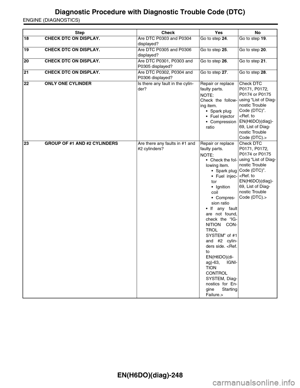
18 CHECK DTC ON DISPLAY.Are DTC P0303 and P0304
displayed?
Go to step 24.Go to step 19.
19 CHECK DTC ON DISPLAY.Are DTC P0305 and P0306
displayed?
Go to step 25.Go to step 20.
20 CHECK DTC ON DISPLAY.Are DTC P0301, P0303 and
P0305 displayed?
Go to step 26.Go to step 21.
21 CHECK DTC ON DISPLAY.Are DTC P0302, P0304 and
P0306 displayed?
Go to step 27.Go to step 28.
22 ONLY ONE CYLINDERIs there any fault in the cylin-
der?
Repair or replace
faulty par ts.
NOTE:Check the follow-
ing item.
•Spark plug
•Fuel injector
•Compression
ratio
Check DTC
P0171, P0172,
P0174 or P0175
using “List of Diag-
nostic Trouble
Code (DTC)”.
EN(H6DO)(diag)-
69, List of Diag-
nostic Trouble
Code (DTC).>
23 GROUP OF #1 AND #2 CYLINDERSAre there any faults in #1 and
#2 cylinders?
Repair or replace
faulty par ts.
NOTE:•Check the fol-
lowing item.
•Spark plug
•Fuel injec-
tor
•Ignition
coil
•Compres-
sion ratio
•If any fault
are not found,
check the “IG-
NITION CON-
TROL
SYSTEM” of #1
and #2 cylin-
ders side.
to
EN(H6DO)(di-
ag)-63, IGNI-
TION
CONTROL
SYSTEM, Diag-
nostics for En-
gine Starting
Failure.>
Check DTC
P0171, P0172,
P0174 or P0175
using “List of Diag-
nostic Trouble
Code (DTC)”.
EN(H6DO)(diag)-
69, List of Diag-
nostic Trouble
Code (DTC).>
Step Check Yes No
Page 1410 of 2453
EN(H6DO)(diag)-249
Diagnostic Procedure with Diagnostic Trouble Code (DTC)
ENGINE (DIAGNOSTICS)
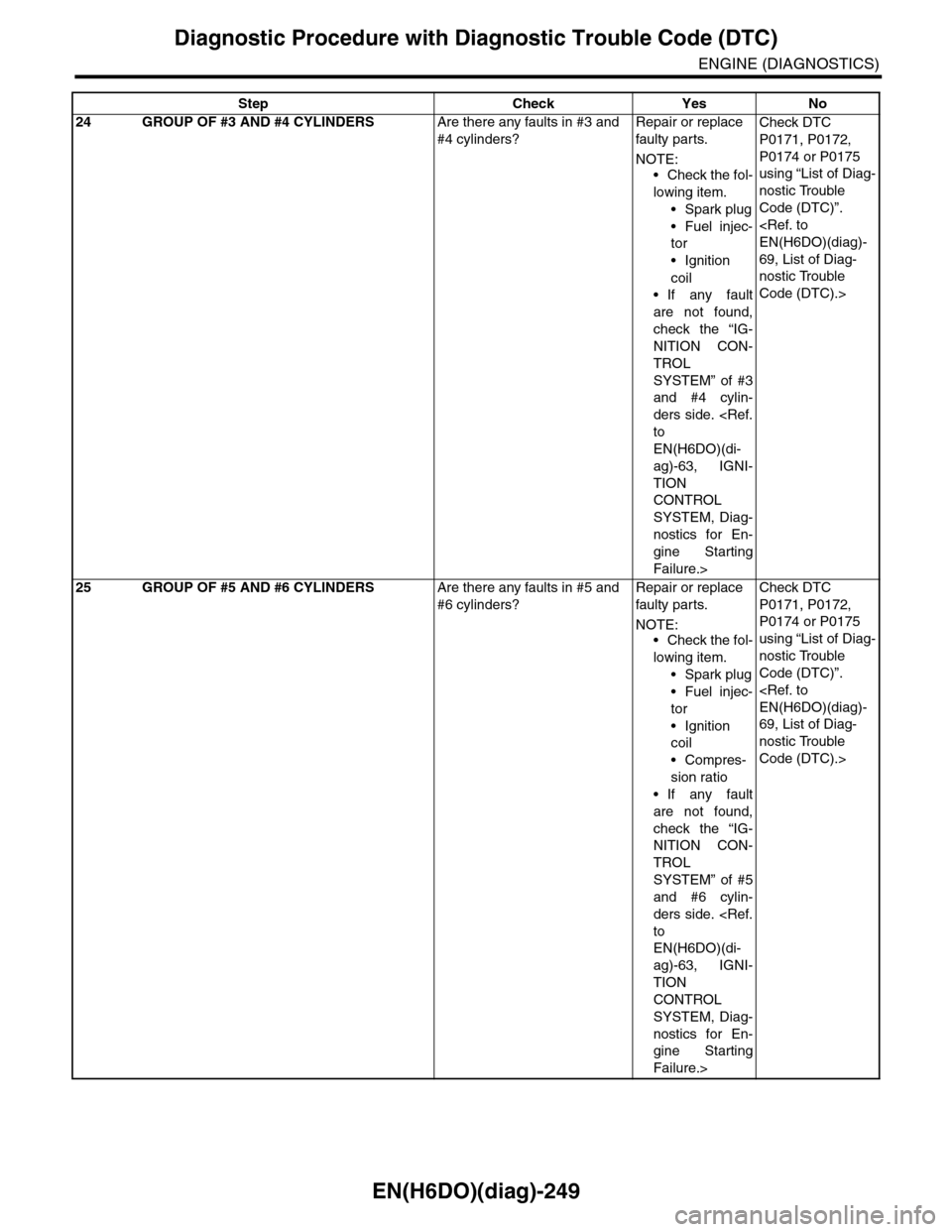
24 GROUP OF #3 AND #4 CYLINDERSAre there any faults in #3 and
#4 cylinders?
Repair or replace
faulty par ts.
NOTE:
•Check the fol-
lowing item.
•Spark plug
•Fuel injec-
tor
•Ignition
coil
•If any fault
are not found,
check the “IG-
NITION CON-
TROL
SYSTEM” of #3
and #4 cylin-
ders side.
to
EN(H6DO)(di-
ag)-63, IGNI-
TION
CONTROL
SYSTEM, Diag-
nostics for En-
gine Starting
Failure.>
Check DTC
P0171, P0172,
P0174 or P0175
using “List of Diag-
nostic Trouble
Code (DTC)”.
EN(H6DO)(diag)-
69, List of Diag-
nostic Trouble
Code (DTC).>
25 GROUP OF #5 AND #6 CYLINDERSAre there any faults in #5 and
#6 cylinders?
Repair or replace
faulty par ts.
NOTE:•Check the fol-
lowing item.
•Spark plug
•Fuel injec-
tor
•Ignition
coil
•Compres-
sion ratio
•If any fault
are not found,
check the “IG-
NITION CON-
TROL
SYSTEM” of #5
and #6 cylin-
ders side.
to
EN(H6DO)(di-
ag)-63, IGNI-
TION
CONTROL
SYSTEM, Diag-
nostics for En-
gine Starting
Failure.>
Check DTC
P0171, P0172,
P0174 or P0175
using “List of Diag-
nostic Trouble
Code (DTC)”.
EN(H6DO)(diag)-
69, List of Diag-
nostic Trouble
Code (DTC).>
Step Check Yes No
Page 1411 of 2453
EN(H6DO)(diag)-250
Diagnostic Procedure with Diagnostic Trouble Code (DTC)
ENGINE (DIAGNOSTICS)
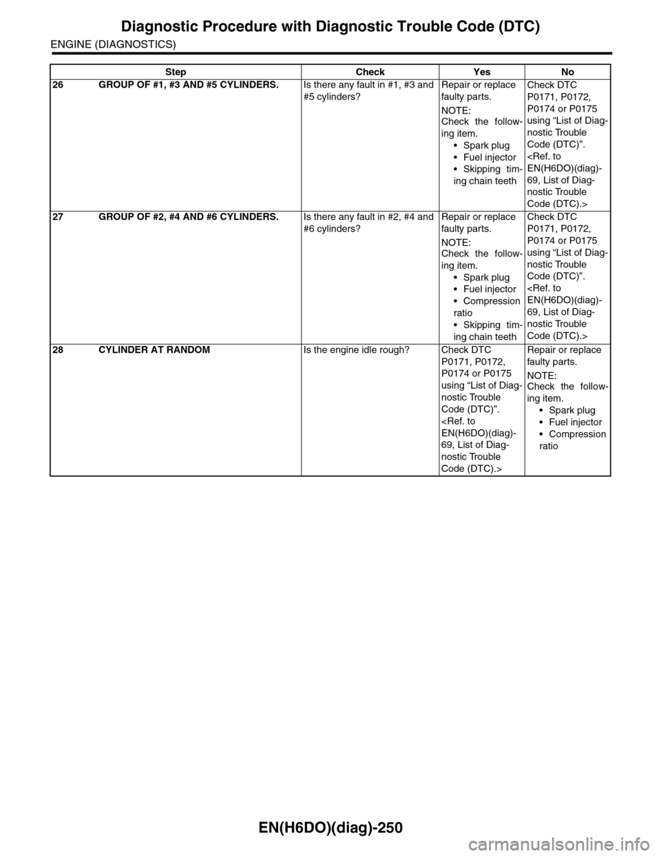
26 GROUP OF #1, #3 AND #5 CYLINDERS.Is there any fault in #1, #3 and
#5 cylinders?
Repair or replace
faulty par ts.
NOTE:
Check the follow-
ing item.
•Spark plug
•Fuel injector
•Skipping tim-
ing chain teeth
Check DTC
P0171, P0172,
P0174 or P0175
using “List of Diag-
nostic Trouble
Code (DTC)”.
EN(H6DO)(diag)-
69, List of Diag-
nostic Trouble
Code (DTC).>
27 GROUP OF #2, #4 AND #6 CYLINDERS.Is there any fault in #2, #4 and
#6 cylinders?
Repair or replace
faulty par ts.
NOTE:Check the follow-
ing item.
•Spark plug
•Fuel injector
•Compression
ratio
•Skipping tim-
ing chain teeth
Check DTC
P0171, P0172,
P0174 or P0175
using “List of Diag-
nostic Trouble
Code (DTC)”.
EN(H6DO)(diag)-
69, List of Diag-
nostic Trouble
Code (DTC).>
28 CYLINDER AT RANDOMIs the engine idle rough? Check DTC
P0171, P0172,
P0174 or P0175
using “List of Diag-
nostic Trouble
Code (DTC)”.
EN(H6DO)(diag)-
69, List of Diag-
nostic Trouble
Code (DTC).>
Repair or replace
faulty par ts.
NOTE:Check the follow-
ing item.
•Spark plug
•Fuel injector
•Compression
ratio
Step Check Yes No
Page 1554 of 2453
EN(H6DO)(diag)-393
General Diagnostic Table
ENGINE (DIAGNOSTICS)
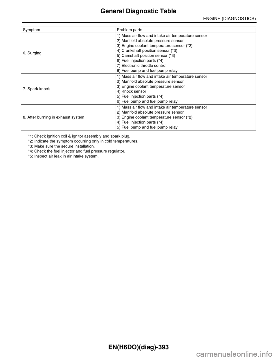
*1: Check ignition coil & ignitor assembly and spark plug.
*2: Indicate the symptom occurring only in cold temperatures.
*3: Make sure the secure installation.
*4: Check the fuel injector and fuel pressure regulator.
*5: Inspect air leak in air intake system.
6. Surging
1) Mass air flow and intake air temperature sensor
2) Manifold absolute pressure sensor
3) Engine coolant temperature sensor (*2)
4) Crankshaft position sensor (*3)
5) Camshaft position sensor (*3)
6) Fuel injection parts (*4)
7) Electronic throttle control
8) Fuel pump and fuel pump relay
7. Spark knock
1) Mass air flow and intake air temperature sensor
2) Manifold absolute pressure sensor
3) Engine coolant temperature sensor
4) Knock sensor
5) Fuel injection parts (*4)
6) Fuel pump and fuel pump relay
8. After burning in exhaust system
1) Mass air flow and intake air temperature sensor
2) Manifold absolute pressure sensor
3) Engine coolant temperature sensor (*2)
4) Fuel injection parts (*4)
5) Fuel pump and fuel pump relay
Symptom Problem parts
Page 1837 of 2453
IG(H6DO)-2
General Description
IGNITION
1. General Description
A: SPECIFICATION
Item Specification
Ignition coil & ignitor ASSY
Typ e F K 0 14 0
Ignition system Independent ignition coil
Manufacturer Diamond Electric
Spar k p l ug
Manufacturer and type NGK: ILFR6B
Thread size (diameter, pitch, length) mm 14, 1.25, 26.5
Spark plug gap mm (in) 0.7 — 0.8 (0.028 — 0.031)
Electrode Iridium
Page 1838 of 2453
IG(H6DO)-3
General Description
IGNITION
B: COMPONENT
C: CAUTION
•Wear work clothing, including a cap, protective goggles and protective shoes during operation.
•Remove contamination including dirt and corrosion before removal, installation or disassembly.
•Keep the disassembled parts in order and protect them from dust and dirt.
•Before removal, installation or disassembly, be sure to clarify the failure. Avoid unnecessary removal, in-
stallation, disassembly and replacement.
•Be careful not to burn yourself, because each part on the vehicle is hot after running.
•Be sure to tighten fasteners including bolts and nuts to the specified torque.
•Place shop jacks or rigid racks at the specified points.
•Before disconnecting connectors of sensors or units, be sure to disconnect the ground cable from battery.
(1) Spark plug Tightening torque: N·m (kgf-m, ft-lb)
(2) Ignition coil & ignitor ASSY T1: 16 (1.6, 11.7)
T2: 21 (2.1, 15.2)
IG-00052
(1)
(1)
(2)
(2)
T1
T2
T2
T1