2009 SUBARU TRIBECA Rear diff code
[x] Cancel search: Rear diff codePage 195 of 2453

ET-9
Rear Entertainment System
ENTERTAINMENT
7. Rear Entertainment System
A: WIRING DIAGRAM
B: INSPECTION
1. CHECK THE DVD-ROM.
Insert a region code 1 DVD-ROM, and check that the display shows images from the DVD when playing back
the media.
NOTE:
Region code 1 is a code for North American DVD-ROM discs. DVD-ROMs of different region codes will not
be played back.
Standard value: Image from DVD should be displayed.
OK: Normal
NG: If the images from the DVD is not displayed, check whether the DVD-ROM is set in the rear entertain-
ment system, whether the correct side is set, type of the DVD-ROM, the existence of any scratches, etc. If
there are no problems on the DVD-ROM, the main body is defective.
NOTE:
The rear entertainment system is not compatible with MP3 files or DVD-Audio.
2. ERROR DISPLAY AND CONTENT
Screen display Trouble contents
INCORRECT CODE When an incorrect number is entered.
DISC ERROR When it is not possible to read the disc due to scratches or
insertion upside down.
REGION CODE ERROR When the region code of the disc does not match (is a region
code other than 1)
MECHA ERROR Replace the rear entertainment system.
NO DISC The DVD switch was pressed when there was no disc inside.
Page 786 of 2453

DI-2
General Description
DIFFERENTIALS
1. General Description
A: SPECIFICATION
1. REAR DIFFERENTIAL
When replacing a rear differential assembly, select the correct one according to the following table.
NOTE:
•Using a different rear differential assembly will cause the drive train and tires to drag or emit abnormal
noise.
•For option code, refer to “ID” section.
2. IDENTIFICATION
Identification label positions are shown in the fol-
lowing figures. For details concerning identification,
refer to the “ID” section.
3. REAR DIFFERENTIAL GEAR OIL
Recommended gear oil:
GL–5 (75W–90)
NOTE:
Each oil manufacturer has its base oil and addi-
tives. Thus, do not mix two or more brands.
4. SERVICE DATA
Rear differential type VA2-type
Identification XX
LSD type—
Ty p e o f g e a r H y p o i d g e a r
Gear ratio (Number of gear teeth) 3.583 (43/12)
Oil capacity 0.82 (0.8 US qt, 0.7 lmp qt)
Rear differential gear oil GL-5
(1) Identification
ID-00114
(1)
(1) Item
(2) Rear differential gear oil
(3) API classification
(4) SAE viscosity No. and applicable temperature
MT-00001
(1)
(4)GL-5(3)
(2)
( C)( F)-30 -26 -15 15
9085W80W75W -90
25 30 -5 0-22-1523328659775
Drive pinion bearing preload Measure with spring measurement. (Mea-
sured from the companion flange bolt)
N (kgf, lb)
12.7 — 32.2 (1.3 — 3.28, 2.9 — 7.24)
Measure with torque wrench
N·m (kgf–m, ft–lb)0.48 — 1.22 (0.045 — 0.124, 0.32 — 0.9)
Hypoid driven gear to drive pinion backlash mm (in) 0.10 — 0.15 (0.0039 — 0.0059)
Page 838 of 2453

DS-21
Rear Hub Unit Bearing
DRIVE SHAFT SYSTEM
6. Rear Hub Unit Bearing
A: REMOVAL
1) Disconnect the ground cable from the battery.
2) Lift-up the vehicle, and then remove the rear
wheels.
3) Lift the crimped section of axle nut.
4) Remove the axle nut using a socket wrench
while depressing the brake pedal.
CAUTION:
Remove the wheel before loosening the axle
nut. Failure to follow this rule may damage the
wheel bearings.
5) Release the parking brake.
6) Remove the disc brake caliper from the rear
housing, and suspend it from the vehicle using a
piece of rope.
7) Remove the disc rotor from the hub.
NOTE:
•Mark the mating surface of hub and disc rotor be-
fore removing the disc rotor to avoid confusing
when installing.
•If it is difficult to remove the disc rotor from the
hub, drive the 8 mm of bolt into the threaded end of
rotor, then remove the rotor.
8) Remove the four bolts from rear arm.
9) Remove the hub unit bearing.
CAUTION:
•Be careful not to damage the magnetic en-
coder.
•Do not get closer the tool which charged
magnetism to magnetic encoder.DS-00038
DS-00358
(1) Magnetic encoder
(2) Rear hub unit bearing
DS-00359
DS-00251
(2)
(1)
DS-00360
Page 845 of 2453

DS-28
Rear Drive Shaft
DRIVE SHAFT SYSTEM
8. Rear Drive Shaft
A: REMOVAL
1) Disconnect the ground cable from the battery.
2) Lift-up the vehicle, and then remove the rear
wheels.
3) Lift the crimped section of axle nut.
4) While applying the parking brake, remove the
axle nut using a socket wrench.
CAUTION:
Remove the wheel before loosening the axle
nut. Failure to follow this rule may damage the
wheel bearings.
5) Remove the rear differential assembly.
VA-type
6) Remove the axle nut and rear drive shaft. If it is
hard to remove, use ST1 and ST2.
ST1 926470000 AXLE SHAFT PULLER
ST2 28099PA110 AXLE SHAFT PULLER
PLATE
CAUTION:
•Do not hammer drive shaft when removing.
•Do not damage the oil seal and magnetic en-
coder.
B: INSTALLATION
1) Insert the EBJ into hub splines.
CAUTION:
•Be careful not to damage the magnetic en-
coder.
•Do not get closer the tool which charged
magnetism to magnetic encoder.
2) Draw the rear drive shaft into specified position.
CAUTION:
Do not hammer drive shaft when installing it.
3) Tighten the axle nut temporarily.
4) Install the rear differential assembly.
VA-type
5) While applying the parking brake and depress-
ing the brake pedal, tighten a new axle nut (olive
color) to the specified torque and lock it securely.
Tightening torque:
240 N·m (24.5 kgf-m, 177 ft-lb)
CAUTION:
•Install the wheel after installation of axle nut.
Failure to follow this rule may damage the
wheel bearing.
•Be sure to tighten the axle nut to specified
torque. Do not overtighten it as this may dam-
age the wheel bearing.
6) Lock the axle nut securely.
DS-00038
DS-00122
ST2ST1
(1) Magnetic encoder
(2) Rear hub unit bearing
DS-00251
(2)
(1)
DS-00048
Page 1199 of 2453

EN(H6DO)(diag)-38
Inspection Mode
ENGINE (DIAGNOSTICS)
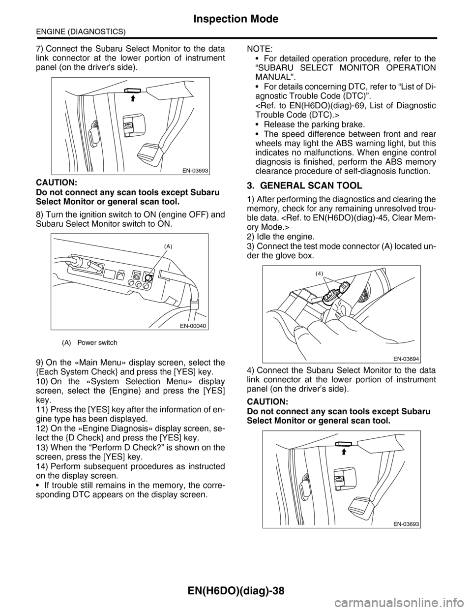
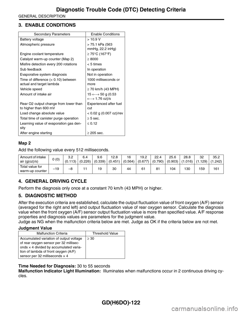
7) Connect the Subaru Select Monitor to the data
link connector at the lower portion of instrument
panel (on the driver's side).
CAUTION:
Do not connect any scan tools except Subaru
Select Monitor or general scan tool.
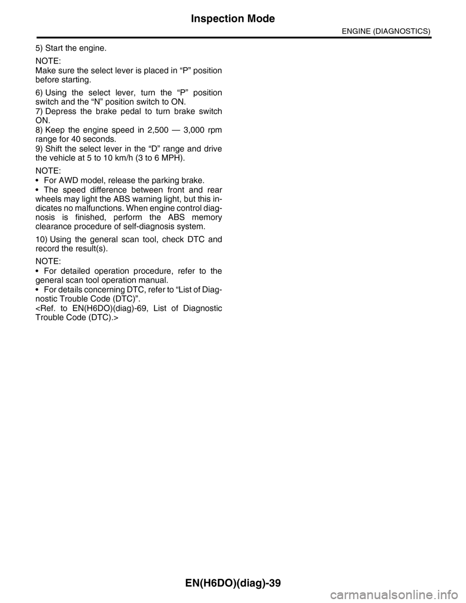
8) Turn the ignition switch to ON (engine OFF) and
Subaru Select Monitor switch to ON.
9) On the «Main Menu» display screen, select the
{Each System Check} and press the [YES] key.
10) On the «System Selection Menu» display
screen, select the {Engine} and press the [YES]
key.
11) Press the [YES] key after the information of en-
gine type has been displayed.
12) On the «Engine Diagnosis» display screen, se-
lect the {D Check} and press the [YES] key.
13) When the “Perform D Check?” is shown on the
screen, press the [YES] key.
14) Perform subsequent procedures as instructed
on the display screen.
•If trouble still remains in the memory, the corre-
sponding DTC appears on the display screen.
NOTE:
•For detailed operation procedure, refer to the
“SUBARU SELECT MONITOR OPERATION
MANUAL”.
•For details concerning DTC, refer to “List of Di-
agnostic Trouble Code (DTC)”.
•Release the parking brake.
•The speed difference between front and rear
wheels may light the ABS warning light, but this
indicates no malfunctions. When engine control
diagnosis is finished, perform the ABS memory
clearance procedure of self-diagnosis function.
3. GENERAL SCAN TOOL
1) After performing the diagnostics and clearing the
memory, check for any remaining unresolved trou-
ble data.
2) Idle the engine.
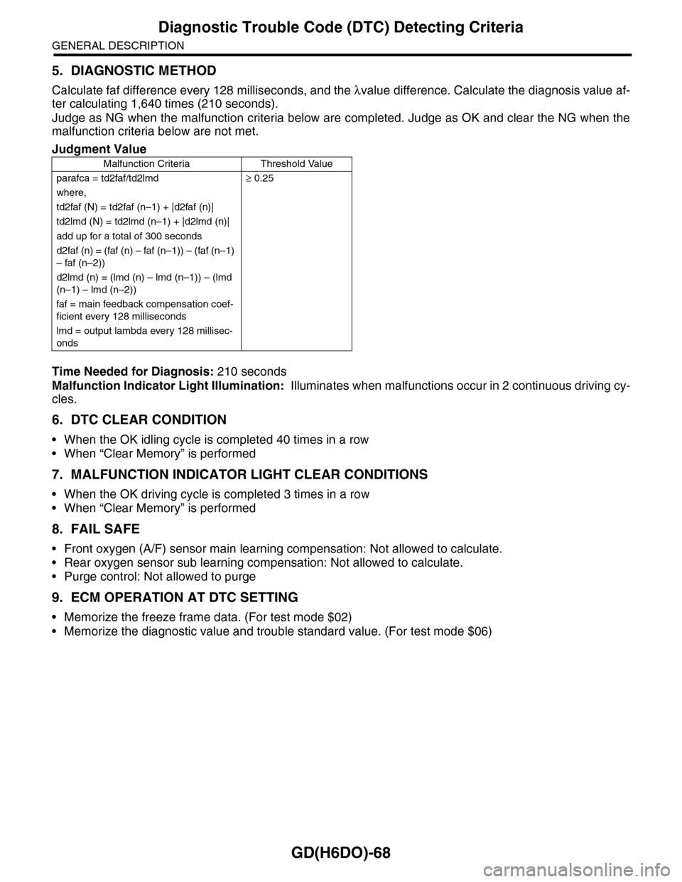
3) Connect the test mode connector (A) located un-
der the glove box.
4) Connect the Subaru Select Monitor to the data
link connector at the lower portion of instrument
panel (on the driver’s side).
CAUTION:
Do not connect any scan tools except Subaru
Select Monitor or general scan tool.
(A) Power switch
EN-03693
(A)
EN-00040
EN-03694
(4)
EN-03693
Page 1200 of 2453

EN(H6DO)(diag)-39
Inspection Mode
ENGINE (DIAGNOSTICS)
5) Start the engine.
NOTE:
Make sure the select lever is placed in “P” position
before starting.
6) Using the select lever, turn the “P” position
switch and the “N” position switch to ON.
7) Depress the brake pedal to turn brake switch
ON.
8) Keep the engine speed in 2,500 — 3,000 rpm
range for 40 seconds.
9) Shift the select lever in the “D” range and drive
the vehicle at 5 to 10 km/h (3 to 6 MPH).
NOTE:
•For AWD model, release the parking brake.
•The speed difference between front and rear
wheels may light the ABS warning light, but this in-
dicates no malfunctions. When engine control diag-
nosis is finished, perform the ABS memory
clearance procedure of self-diagnosis system.
10) Using the general scan tool, check DTC and
record the result(s).
NOTE:
•For detailed operation procedure, refer to the
general scan tool operation manual.
•For details concerning DTC, refer to “List of Diag-
nostic Trouble Code (DTC)”.
Page 1680 of 2453

GD(H6DO)-68
Diagnostic Trouble Code (DTC) Detecting Criteria
GENERAL DESCRIPTION
5. DIAGNOSTIC METHOD
Calculate faf difference every 128 milliseconds, and the λvalue difference. Calculate the diagnosis value af-
ter calculating 1,640 times (210 seconds).
Judge as NG when the malfunction criteria below are completed. Judge as OK and clear the NG when the
malfunction criteria below are not met.
Time Needed for Diagnosis: 210 seconds
Malfunction Indicator Light Illumination: Illuminates when malfunctions occur in 2 continuous driving cy-
cles.
6. DTC CLEAR CONDITION
•When the OK idling cycle is completed 40 times in a row
•When “Clear Memory” is performed
7. MALFUNCTION INDICATOR LIGHT CLEAR CONDITIONS
•When the OK driving cycle is completed 3 times in a row
•When “Clear Memory” is performed
8. FAIL SAFE
•Front oxygen (A/F) sensor main learning compensation: Not allowed to calculate.
•Rear oxygen sensor sub learning compensation: Not allowed to calculate.
•Purge control: Not allowed to purge
9. ECM OPERATION AT DTC SETTING
•Memorize the freeze frame data. (For test mode $02)
•Memorize the diagnostic value and trouble standard value. (For test mode $06)
Judgment Value
Malfunction Criteria Threshold Value
parafca = td2faf/td2lmd≥ 0.25
where,
td2faf (N) = td2faf (n–1) + |d2faf (n)|
td2lmd (N) = td2lmd (n–1) + |d2lmd (n)|
add up for a total of 300 seconds
d2faf (n) = (faf (n) – faf (n–1)) – (faf (n–1)
– faf (n–2))
d2lmd (n) = (lmd (n) – lmd (n–1)) – (lmd
(n–1) – lmd (n–2))
faf = main feedback compensation coef-
ficient every 128 milliseconds
lmd = output lambda every 128 millisec-
onds
Page 1734 of 2453

GD(H6DO)-122
Diagnostic Trouble Code (DTC) Detecting Criteria
GENERAL DESCRIPTION
3. ENABLE CONDITIONS
Map 2
Add the following value every 512 milliseconds.
4. GENERAL DRIVING CYCLE
Perform the diagnosis only once at a constant 70 km/h (43 MPH) or higher.
5. DIAGNOSTIC METHOD
After the execution criteria are established, calculate the output fluctuation value of front oxygen (A/F) sensor
(averaged for the right and left) and output fluctuation value of rear oxygen sensor. Calculate the diagnosis
value when the front oxygen (A/F) sensor output fluctuation value is more than specified value. A/F response
properties and diagnosis values are parameters for the judgment value.
Judge as NG when the malfunction criteria below are met. Judge as OK if the criteria below are not met.
Time Needed for Diagnosis: 30 to 55 seconds
Malfunction Indicator Light Illumination: Illuminates when malfunctions occur in 2 continuous driving cy-
cles.
Secondary Parameters Enable Conditions
Battery voltage > 10.9 V
Atmospheric pressure > 75.1 kPa (563
mmHg, 22.2 inHg)
Engine coolant temperature≥ 75°C (167°F)
Catalyst warm-up counter (Map 2)≥ 8000
Misfire detection every 200 rotations < 5 times
Sub feedback In operation
Evaporative system diagnosis Not in operation
Time of difference (< 0.10) between
actual and target lambda
1000 milliseconds or
more
Ve h i c l e s p e e d≥ 70 km/h (43 MPH)
Amount of intake air 15 ←→ 50 g (0.53
←→ 1.76 oz)/s
Rear O2 output change from lower than
to higher than 600 mV
Experienced after fuel
cut
Load change absolute value < 0.02 g (0.007 oz)/rev
To t a l t i m e o f c a n i s t e r p u r g e o p e r a t i o n≥ 5 sec.
Learning value of evaporation gas den-
sity
≤ 0.12
After engine starting≥ 205 sec.
Amount of intake
air (g(oz)/s)0 (0)3.2
(0.113)
6.4
(0.226)
9.6
(0.339)
12.8
(0.451)
16
(0.564)
19.2
(0.677)
22.4
(0.790)
25.6
(0.903)
28.8
(1.016)
32
(1.129)
35.2
(1.242)
To t a l v a l u e f o r
warm-up counter–19 –8 11 19 30 44 61 81 104 130 159 161
Judgment Value
Malfunction Criteria Threshold Value
Accumulated variation of output voltage
of rear oxygen sensor per 32 millisec-
onds × 4 divided by accumulated varia-
tion of lambda of front oxygen (A/F)
sensor per 32 milliseconds × 4
≥ 30