Page 810 of 2453

DI-26
Rear Differential (VA–type)
DIFFERENTIALS
17) Tighten the bolt of lock plate to specified
torque.
Tightening torque:
25 N·m (2.5 kgf-m, 18.1 ft-lb)
18) Recheck the hypoid driven gear to pinion back-
lash.
Backlash:
0.10 — 0.15 mm (0.0039 — 0.0059 in)
19) Checking and adjusting the tooth contact of hy-
poid driven gear
(1) Apply an even coat of red lead on both sides
of three or four teeth on the hypoid driven gear.
Check the contact pattern after rotating the hy-
poid driven gear several revolutions back and
forth until a definite contact pattern appears on
the hypoid driven gear.
(2) When the contact pattern is not correct, re-
adjust.
NOTE:
Be sure to wipe off the red lead completely after the
adjustment is completed.
•Correct tooth contact
Check item: Tooth contact pattern is slightly
shifted towards the toe side under no-load rota-
tion. (When driving it will move toward the heel
side.)
•Face contact
Check item: Backlash is too large.
Contact pattern
Corrective action: Increase thickness of drive pin-
ion height adjusting washer in order to bring drive
pinion close to hypoid driven gear.
DI-00364
DI-00172
(A) Toe side
(B) Heel side
MT-01401
(A)
(B)
AT-00208
AT-00212
Page 1036 of 2453

VDC(diag)-44
Diagnostic Procedure with Diagnostic Trouble Code (DTC)
VEHICLE DYNAMICS CONTROL (VDC) (DIAGNOSTICS)
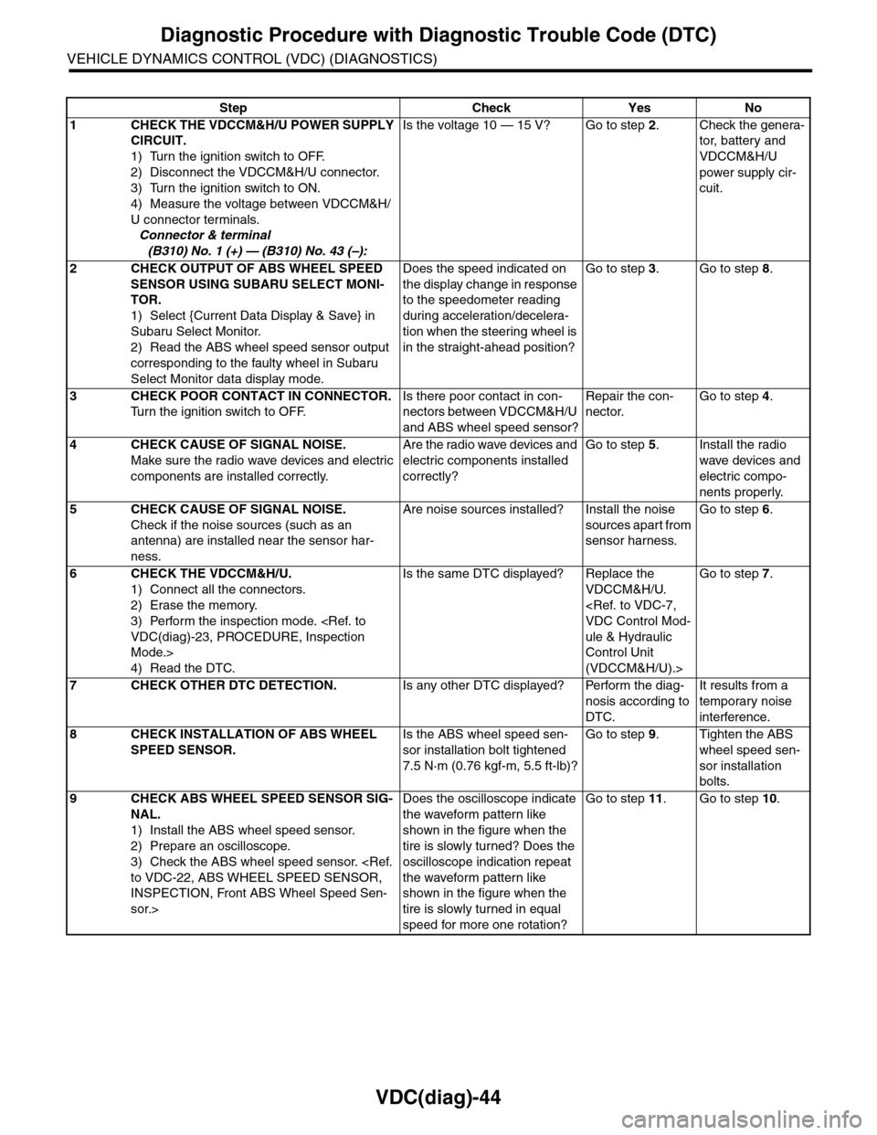
Step Check Yes No
1CHECK THE VDCCM&H/U POWER SUPPLY
CIRCUIT.
1) Turn the ignition switch to OFF.
2) Disconnect the VDCCM&H/U connector.
3) Turn the ignition switch to ON.
4) Measure the voltage between VDCCM&H/
U connector terminals.
Connector & terminal
(B310) No. 1 (+) — (B310) No. 43 (–):
Is the voltage 10 — 15 V? Go to step 2.Check the genera-
tor, batter y and
VDCCM&H/U
power supply cir-
cuit.
2CHECK OUTPUT OF ABS WHEEL SPEED
SENSOR USING SUBARU SELECT MONI-
TOR.
1) Select {Current Data Display & Save} in
Subaru Select Monitor.
2) Read the ABS wheel speed sensor output
corresponding to the faulty wheel in Subaru
Select Monitor data display mode.
Does the speed indicated on
the display change in response
to the speedometer reading
during acceleration/decelera-
tion when the steering wheel is
in the straight-ahead position?
Go to step 3.Go to step 8.
3CHECK POOR CONTACT IN CONNECTOR.
Tu r n t h e i g n i t i o n s w i t c h t o O F F.
Is there poor contact in con-
nectors between VDCCM&H/U
and ABS wheel speed sensor?
Repair the con-
nector.
Go to step 4.
4CHECK CAUSE OF SIGNAL NOISE.
Make sure the radio wave devices and electric
components are installed correctly.
Are the radio wave devices and
electric components installed
correctly?
Go to step 5.Install the radio
wave devices and
electric compo-
nents properly.
5CHECK CAUSE OF SIGNAL NOISE.
Check if the noise sources (such as an
antenna) are installed near the sensor har-
ness.
Are noise sources installed? Install the noise
sources apart from
sensor harness.
Go to step 6.
6CHECK THE VDCCM&H/U.
1) Connect all the connectors.
2) Erase the memory.
3) Perform the inspection mode.
VDC(diag)-23, PROCEDURE, Inspection
Mode.>
4) Read the DTC.
Is the same DTC displayed? Replace the
VDCCM&H/U.
VDC Control Mod-
ule & Hydraulic
Control Unit
(VDCCM&H/U).>
Go to step 7.
7CHECK OTHER DTC DETECTION.Is any other DTC displayed? Perform the diag-
nosis according to
DTC.
It results from a
temporary noise
interference.
8CHECK INSTALLATION OF ABS WHEEL
SPEED SENSOR.
Is the ABS wheel speed sen-
sor installation bolt tightened
7.5 N·m (0.76 kgf-m, 5.5 ft-lb)?
Go to step 9.Tighten the ABS
wheel speed sen-
sor installation
bolts.
9CHECK ABS WHEEL SPEED SENSOR SIG-
NAL.
1) Install the ABS wheel speed sensor.
2) Prepare an oscilloscope.
3) Check the ABS wheel speed sensor.
to VDC-22, ABS WHEEL SPEED SENSOR,
INSPECTION, Front ABS Wheel Speed Sen-
sor.>
Does the oscilloscope indicate
the waveform pattern like
shown in the figure when the
tire is slowly turned? Does the
oscilloscope indication repeat
the waveform pattern like
shown in the figure when the
tire is slowly turned in equal
speed for more one rotation?
Go to step 11.Go to step 10.
Page 2099 of 2453

5AT-83
Drive Pinion Shaft Assembly
AUTOMATIC TRANSMISSION
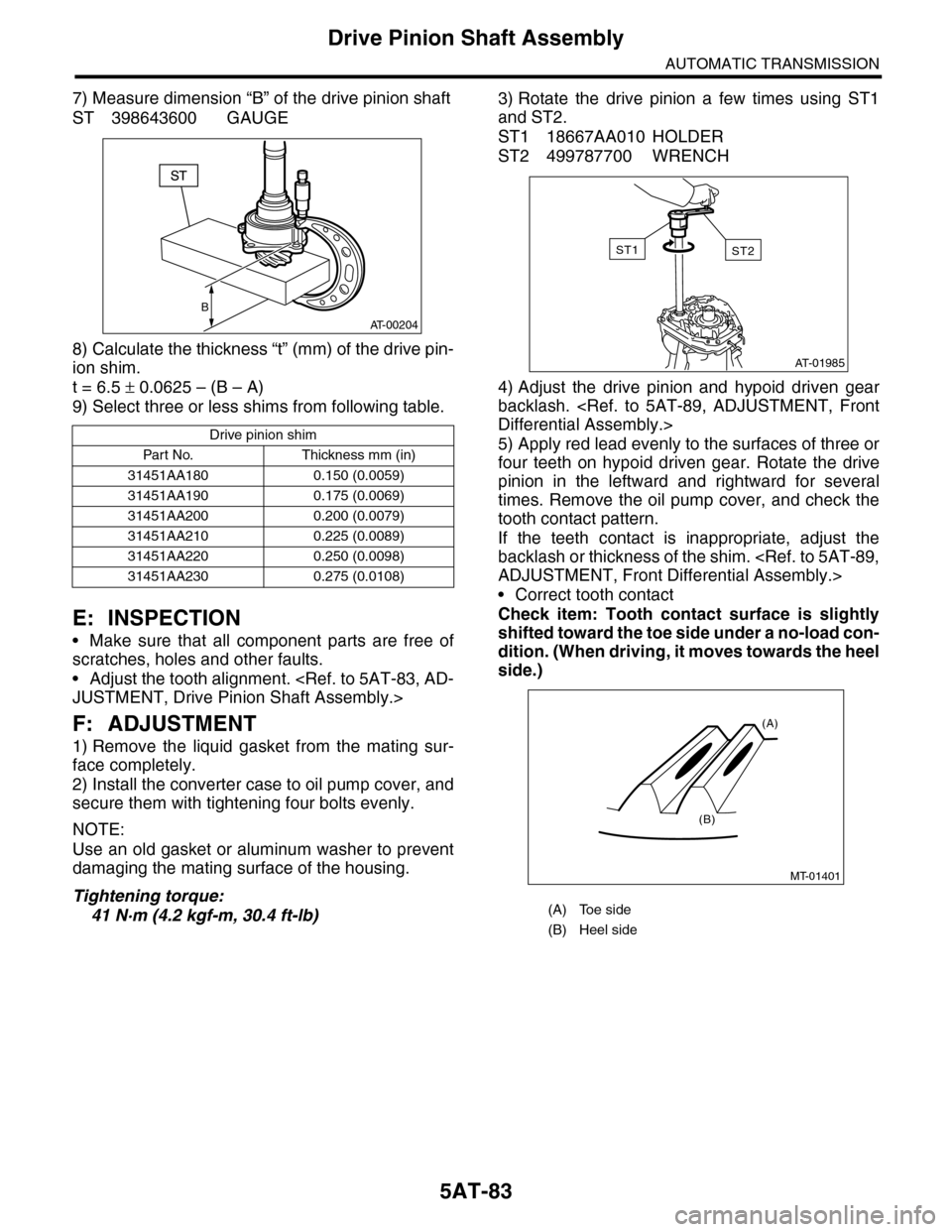
7) Measure dimension “B” of the drive pinion shaft
ST 398643600 GAUGE
8) Calculate the thickness “t” (mm) of the drive pin-
ion shim.
t = 6.5 ± 0.0625 – (B – A)
9) Select three or less shims from following table.
E: INSPECTION
•Make sure that all component parts are free of
scratches, holes and other faults.
•Adjust the tooth alignment.
JUSTMENT, Drive Pinion Shaft Assembly.>
F: ADJUSTMENT
1) Remove the liquid gasket from the mating sur-
face completely.
2) Install the converter case to oil pump cover, and
secure them with tightening four bolts evenly.
NOTE:
Use an old gasket or aluminum washer to prevent
damaging the mating surface of the housing.
Tightening torque:
41 N·m (4.2 kgf-m, 30.4 ft-lb)
3) Rotate the drive pinion a few times using ST1
and ST2.
ST1 18667AA010 HOLDER
ST2 499787700 WRENCH
4) Adjust the drive pinion and hypoid driven gear
backlash.
Differential Assembly.>
5) Apply red lead evenly to the surfaces of three or
four teeth on hypoid driven gear. Rotate the drive
pinion in the leftward and rightward for several
times. Remove the oil pump cover, and check the
tooth contact pattern.
If the teeth contact is inappropriate, adjust the
backlash or thickness of the shim.
ADJUSTMENT, Front Differential Assembly.>
•Correct tooth contact
Check item: Tooth contact surface is slightly
shifted toward the toe side under a no-load con-
dition. (When driving, it moves towards the heel
side.)
Drive pinion shim
Par t No. Thickness mm (in)
31451AA180 0.150 (0.0059)
31451AA190 0.175 (0.0069)
31451AA200 0.200 (0.0079)
31451AA210 0.225 (0.0089)
31451AA220 0.250 (0.0098)
31451AA230 0.275 (0.0108)
B
AT-00204
(A) Toe side
(B) Heel side
AT-01985
ST2ST1
MT-01401
(A)
(B)