2009 SUBARU TRIBECA run flat
[x] Cancel search: run flatPage 460 of 2453

LAN(diag)-4
Check List for Interview
LAN SYSTEM (DIAGNOSTICS)
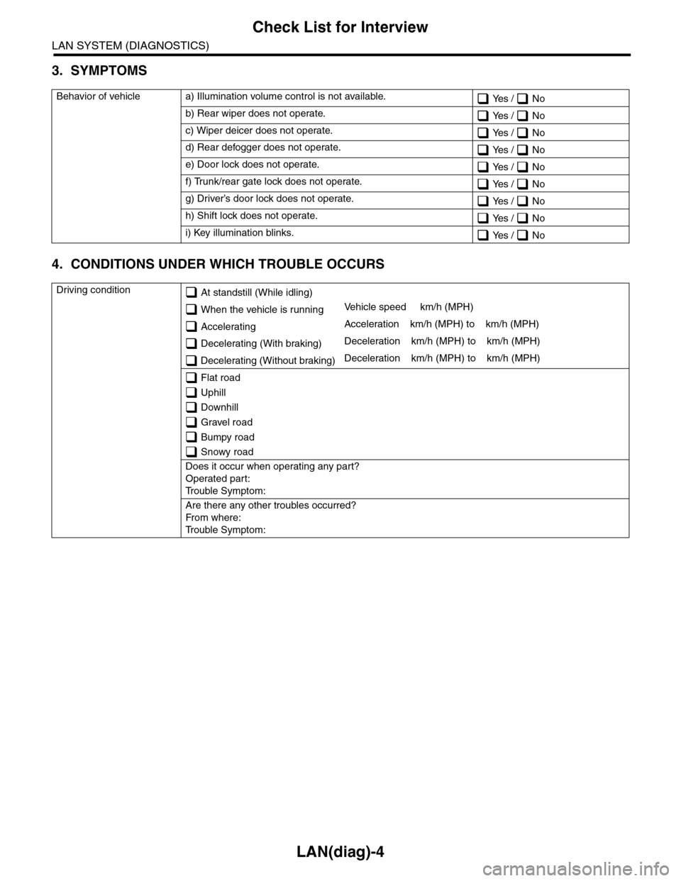
3. SYMPTOMS
4. CONDITIONS UNDER WHICH TROUBLE OCCURS
Behavior of vehicle a) Illumination volume control is not available. Yes / No
b) Rear wiper does not operate. Yes / No
c) Wiper deicer does not operate. Yes / No
d) Rear defogger does not operate. Yes / No
e) Door lock does not operate. Yes / No
f) Trunk/rear gate lock does not operate. Yes / No
g) Driver’s door lock does not operate. Yes / No
h) Shift lock does not operate. Yes / No
i) Key illumination blinks. Yes / No
Driving condition At standstill (While idling)
When the vehicle is runningVe h i c l e s p e e d k m / h ( M P H )
AcceleratingAcceleration km/h (MPH) to km/h (MPH)
Decelerating (With braking)Deceleration km/h (MPH) to km/h (MPH)
Decelerating (Without braking)Deceleration km/h (MPH) to km/h (MPH)
Flat road
Uphill
Downhill
Gravel road
Bumpy road
Snowy road
Does it occur when operating any part?
Operated part:
Tr o u b l e S y m p t o m :
Are there any other troubles occurred?
Fr o m wh er e :
Tr o u b l e S y m p t o m :
Page 734 of 2453

BR-20
Rear Disc Rotor
BRAKE
6. Rear Disc Rotor
A: REMOVAL
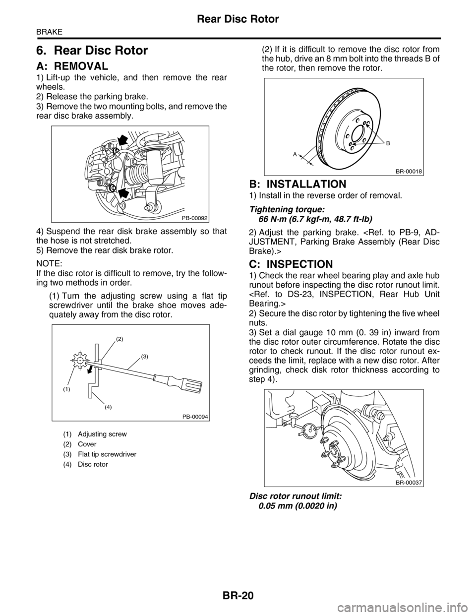
1) Lift-up the vehicle, and then remove the rear
wheels.
2) Release the parking brake.
3) Remove the two mounting bolts, and remove the
rear disc brake assembly.
4) Suspend the rear disk brake assembly so that
the hose is not stretched.
5) Remove the rear disk brake rotor.
NOTE:
If the disc rotor is difficult to remove, try the follow-
ing two methods in order.
(1) Turn the adjusting screw using a flat tip
screwdriver until the brake shoe moves ade-
quately away from the disc rotor.
(2) If it is difficult to remove the disc rotor from
the hub, drive an 8 mm bolt into the threads B of
the rotor, then remove the rotor.
B: INSTALLATION
1) Install in the reverse order of removal.
Tightening torque:
66 N·m (6.7 kgf-m, 48.7 ft-lb)
2) Adjust the parking brake.
Brake).>
C: INSPECTION
1) Check the rear wheel bearing play and axle hub
runout before inspecting the disc rotor runout limit.
2) Secure the disc rotor by tightening the five wheel
nuts.
3) Set a dial gauge 10 mm (0. 39 in) inward from
the disc rotor outer circumference. Rotate the disc
rotor to check runout. If the disc rotor runout ex-
ceeds the limit, replace with a new disc rotor. After
grinding, check disk rotor thickness according to
step 4).
Disc rotor runout limit:
0.05 mm (0.0020 in)
(1) Adjusting screw
(2) Cover
(3) Flat tip screwdriver
(4) Disc rotor
PB-00092
(1)
(4)
(2)
(3)
PB-00094
B
A
BR-00018
BR-00037
Page 849 of 2453

DS-32
General Diagnostic Table
DRIVE SHAFT SYSTEM
9. General Diagnostic Table
A: INSPECTION
NOTE:
Vibration while cruising may be caused by an unbalanced tire, improper tire inflation pressure, improper
wheel alignment, etc.
Symptom Possible cause Corrective action
Noise or vibration from propeller shaftCenter bearing Check the center bearing.
peller Shaft.>
Runout of propeller shaft Check for deflection of the propeller shaft.
INSPECTION, Propeller Shaft.>
Loose or gap at connections Check the joints and connectors.
Propeller Shaft.>
Check the spline and bearing.
peller Shaft.>
Abnormal wheel vibrationWheel is out of balance. Check the wheel balance.
Fr o n t wh e el al i gn me n t Che ck t h e f r on t whe e l a li g nm en t .
Rear wheel alignment Check the rear wheel alignment.
Fr o n t s tr ut Che ck t h e f r on t st r u t . < R e f. t o F S - 21 , I N S P EC -
TION, Front Strut.>
Rear shock absorber Check the rear shock absorber.
Fr o n t d r i ve sh af t Che ck t h e f r on t dr i ve s ha f t. < R e f. t o D S - 2 7,
INSPECTION, Front Drive Shaft.>
Rear drive shaft Check the rear driveshaft.
Fr o n t h ub u ni t b e ar i n g Che ck th e f r on t h ub u n it b e ar i n g. < Re f. to DS - 2 0 ,
INSPECTION, Front Hub Unit Bearing.>
Rear hub unit bearing Check the rear hub unit bearing.
Noise from the underbodyWheel is out of balance. Check the wheel balance.
Fr o n t wh e el al i gn me n t Che ck t h e f r on t whe e l a li g nm en t .
Rear wheel alignment Check the rear wheel alignment.
Fr o n t s tr ut Che ck t h e f r on t st r u t . < R e f. t o F S - 21 , I N S P EC -
TION, Front Strut.>
Rear shock absorber Check the rear shock absorber.
Page 854 of 2453

FS-6
Wheel Alignment
FRONT SUSPENSION
2. Wheel Alignment
A: INSPECTION
Check the following items before performing the wheel alignment measurement.
Check items before measuring wheel alignment:
•Tire inflation pressure
•Uneven wear of RH and LH tires, or difference of sizes
•Tire runout
•Excessive play and wear of ball joint
•Excessive play and wear of tie rod end
•Excessive play of wheel bearing
•Right and left wheel base imbalance
•Deformation and excessive play of steering link
•Deformation and excessive play of suspension parts
Check, adjust and measure the wheel alignment in accordance with the procedures indicated in the figure.
Wheel arch height (front and rear wheels)
↓
Camber (front and rear wheels)
↓
Caster (front wheel)
↓
Steering angle
↓
Fr o nt wh ee l to e –i n
↓
Rear wheel toe–in
↓
Thrust angle
Page 872 of 2453

FS-24
General Diagnostic Table
FRONT SUSPENSION
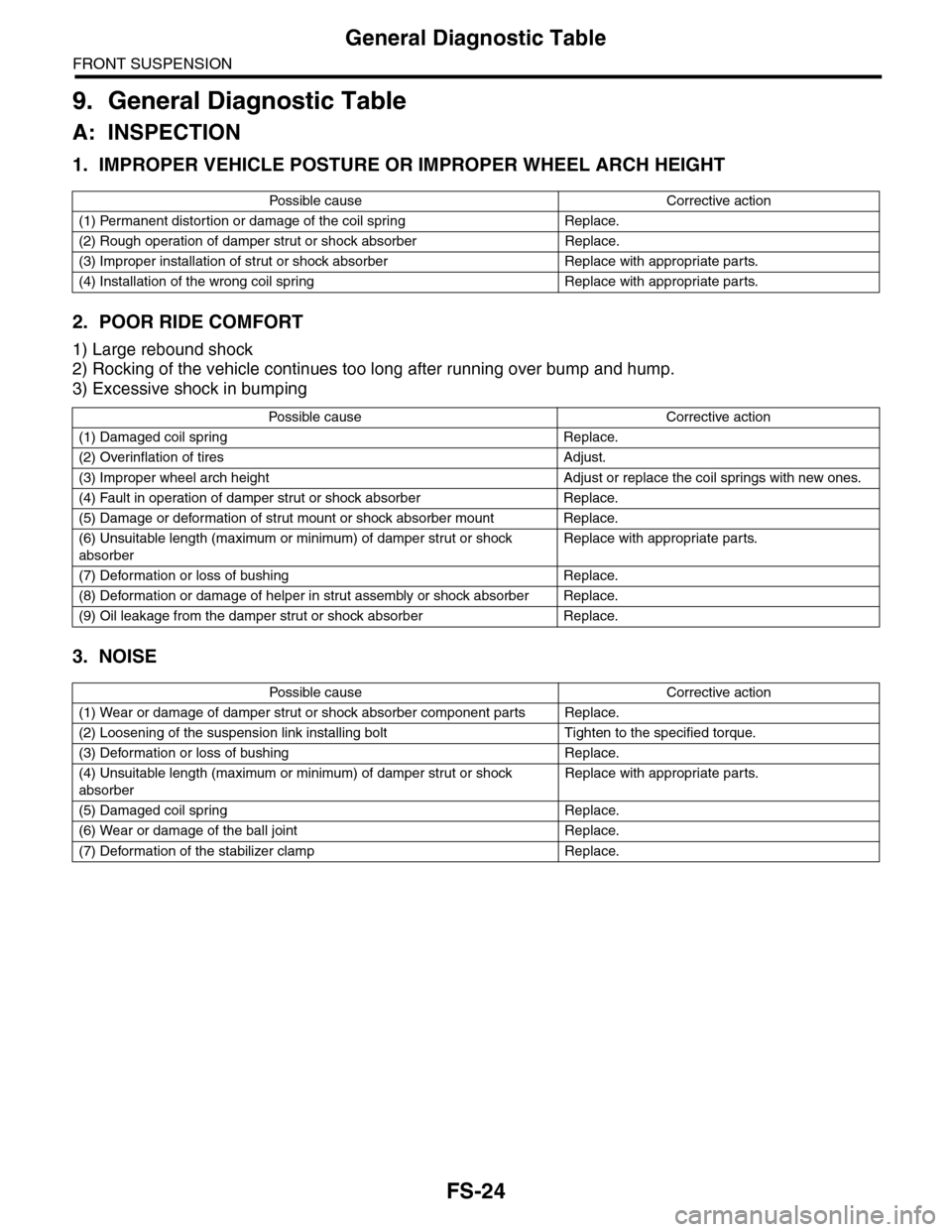
9. General Diagnostic Table
A: INSPECTION
1. IMPROPER VEHICLE POSTURE OR IMPROPER WHEEL ARCH HEIGHT
2. POOR RIDE COMFORT
1) Large rebound shock
2) Rocking of the vehicle continues too long after running over bump and hump.
3) Excessive shock in bumping
3. NOISE
Po ss ibl e c a us e C o r r e ct ive ac ti o n
(1) Permanent distortion or damage of the coil spring Replace.
(2) Rough operation of damper strut or shock absorber Replace.
(3) Improper installation of strut or shock absorber Replace with appropriate parts.
(4) Installation of the wrong coil spring Replace with appropriate parts.
Po ss ibl e ca us e C or r e ct i ve a ct io n
(1) Damaged coil spring Replace.
(2) Overinflation of tires Adjust.
(3) Improper wheel arch height Adjust or replace the coil springs with new ones.
(4) Fault in operation of damper strut or shock absorber Replace.
(5) Damage or deformation of strut mount or shock absorber mount Replace.
(6) Unsuitable length (maximum or minimum) of damper strut or shock
absorber
Replace with appropriate parts.
(7) Deformation or loss of bushing Replace.
(8) Deformation or damage of helper in strut assembly or shock absorber Replace.
(9) Oil leakage from the damper strut or shock absorber Replace.
Po ss ibl e c a us e C o r r e ct ive ac ti o n
(1) Wear or damage of damper strut or shock absorber component parts Replace.
(2) Loosening of the suspension link installing bolt Tighten to the specified torque.
(3) Deformation or loss of bushing Replace.
(4) Unsuitable length (maximum or minimum) of damper strut or shock
absorber
Replace with appropriate parts.
(5) Damaged coil spring Replace.
(6) Wear or damage of the ball joint Replace.
(7) Deformation of the stabilizer clamp Replace.
Page 930 of 2453

PS-50
General Diagnostic Table
POWER ASSISTED SYSTEM (POWER STEERING)
1. NOISE & VIBRATION
CAUTION:
Do not keep the relief valve operated over five seconds at any time or inner parts of the oil pump may
be damaged due to rapid increase of fluid temperature.
NOTE:
•A screeching noise may be heard immediately after the engine start in extremely cold conditions. In this
case, if the noise goes off during warm-up there is no abnormal function in the system. This is due to the fluid
characteristics in extremely cold condition.
•The oil pump normally makes a small whining noise due to its mechanism. Even if a noise is heard when
steering wheel is turned at stand still, there is no abnormal function in the system provided that the noise
eliminates when the vehicle is driving.
•When turning the steering wheel with the brake applied when the vehicle is parked, a screeching noise
may be generated by the brake disc and pads. This is not a fault in the steering system.
•There may be a small vibration around the steering devices when turning the steering wheel at standstill,
even though the component parts are operating properly.
Hydraulic systems are likely to generate this kind of vibration as well as working noise and fluid noise be-
cause of combined conditions, i.e., road surface and tire surface, engine speed and turning speed of steering
wheel, fluid temperature and braking condition.
These conditions do not indicate a problem in the system.
Confirm vibration for an AT model, by applying the parking brake on a concrete surface, shifting into the “D”
range, and turning the steering wheel repeatedly from slow to rapid, step by step.
Tr o u b l e P o s s i b l e c a u s e C o r r e c t i v e a c t i o n
Hiss noise (continuous)
While engine is running.
Relief valve emits operating sound when steering wheel is
completely turned in either direction. (Do not keep this
condition over five seconds.)
Normal
Relief valve emits operating sound when steering wheel is
not turned. This means that the relief valve is defective. Replace the oil pump.
Rattling noise (intermittent)
While engine is running.
Interference with adjacent parts
Check the clearance.
Correct if necessary.
Loosened installation of oil pump, oil tank, pump bracket,
gearbox or crossmemberRetighten.
Loose oil pump pulley or other pulley(s) Retighten.
Looseness of linkage, play of steering, improper tightening
(looseness) of suspension joint or steering columnRetighten or replace.
Sound generates from the inside of gearbox or oil pump.Replace faulty parts in the gear-
box or oil pump.
Knocking
When turning steering wheel in
both directions with small angle
repeatedly at engine ON or OFF.
Excessive backlash
Loosened lock nut for adjusting backlashAdjust and retighten.
Insufficient tightening or play in the tie–rod or tie–rod end Retighten or replace.
Grinding noise (continuous)
While engine is running.
Air in vane pump
Inspect and retighten the fluid
line connection.
Refill the fluid and vent air.
Va n e p u m p s e i z i n g R e p l a c e t h e o i l p u m p.
Oil pump pulley bearing seized Replace the oil pump.
Folded hose, flattened pipe Replace.
Squeal, squeak (intermittent or
continuous)
While engine is running.
Improper adjustment of pulley belt
Damaged or over tensioned pulley belt
Unequal length of pulley belts
Adjust or replace.
(Replace two belts as a set.)
Runout or dirty V–groove surface of oil pump pulley Clean or replace.
Page 931 of 2453

PS-51
General Diagnostic Table
POWER ASSISTED SYSTEM (POWER STEERING)
Sizzling noise (continuous)
While engine is running.
Fluid aeration
Fix the faulty part causing aera-
tion.
Replace the fluid and vent air.
Damaged pipe of gearbox Replace the pipe.
Fa u lt y i n si de of h os e o r pi p e
Flattened hose or pipeRepair or replace.
Abnormal inside of oil tank Replace.
Removed oil tank cap Install cap.
Whistle (continuous)
While engine is running.Fa u lt y p i pe of g ea r b ox o r fa ul t y h os eReplace the faulty parts of the
gearbox or the hose.
Whine or growl (intermittent or
continuous)
While engine is running with/
without steering turned.
Looseness of oil pump, oil pump bracket attachment Retighten.
Fa u lt in s id e o f oi l p u mp o r h os e
Replace the oil pump or hose, if
the noise can be heard when
vehicle is running as well as
being stopped.
To r q u e c o n v e r t e r g r o w l , a i r c o n d i t i o n e r c o m p r e s s i o n g r o w lRemove the power steering pul-
ley belt and check.
Grinding noise (continuous)
While engine is running with the
steering turned.
Fa u lt in s id e o f ge a rb oxReplace the faulty parts of gear-
box.
Fa u lt y s t ee r i ng sh af t b ea r i ng A pp l y gr ea s e o r r e p la ce.
Occurs when turning the steering wheel with brakes (ser-
vice or parking) applied.
If the noise goes off when brake
is released, it is normal.
Vibration
While engine is running with/
without steering turned.
Engine speed is too low. Adjust, and notify customer.
Air in vane pumpRepair faulty part
Ve n t a i r.
Damaged valve in oil pump or gearboxReplace the faulty parts in gear-
box and oil pump.
Excessive play in steering, looseness of suspension parts Retighten.
Tr o u b l e P o s s i b l e c a u s e C o r r e c t i v e a c t i o n
Page 950 of 2453

RS-17
General Diagnostic Table
REAR SUSPENSION
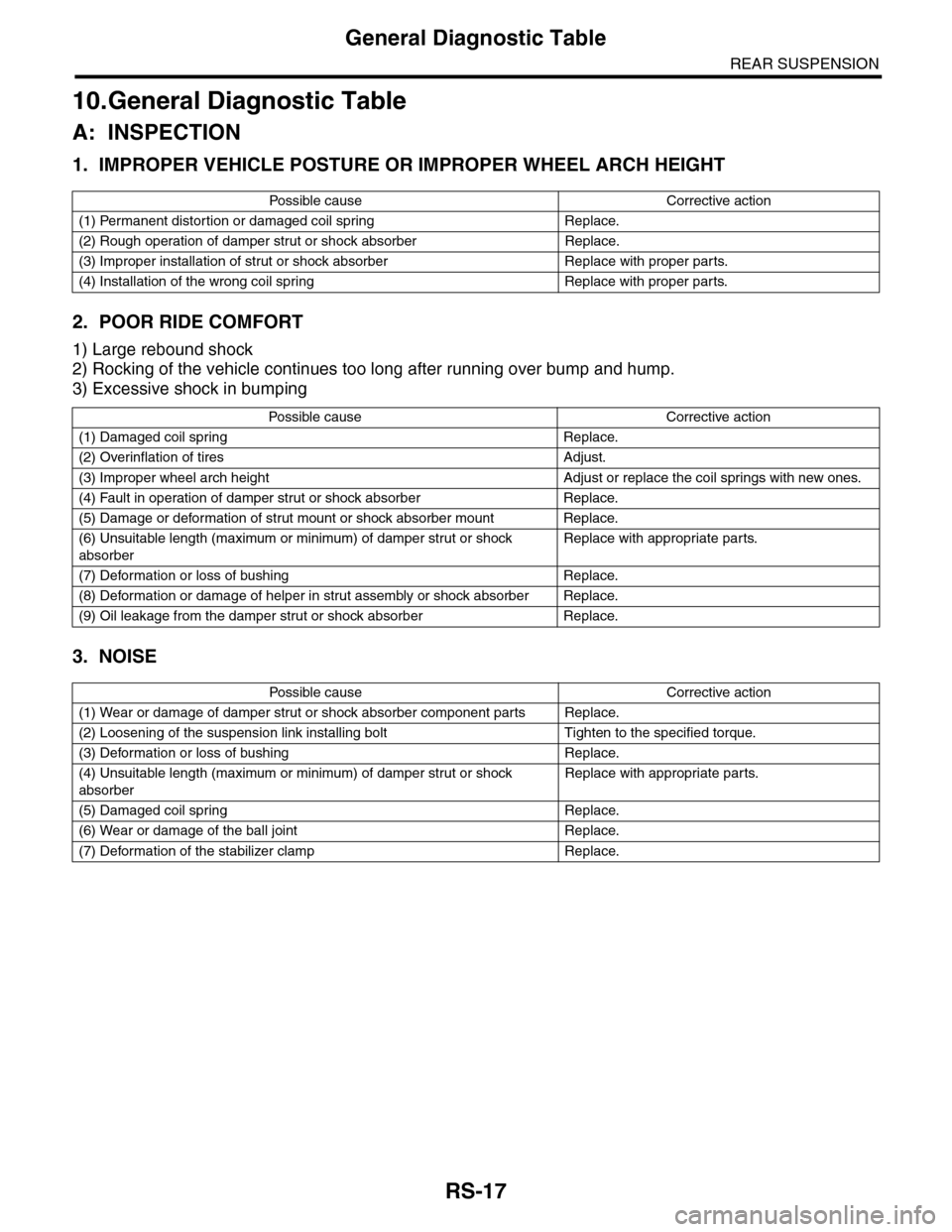
10.General Diagnostic Table
A: INSPECTION
1. IMPROPER VEHICLE POSTURE OR IMPROPER WHEEL ARCH HEIGHT
2. POOR RIDE COMFORT
1) Large rebound shock
2) Rocking of the vehicle continues too long after running over bump and hump.
3) Excessive shock in bumping
3. NOISE
Po ss ibl e c a us e C o r r e ct ive ac ti o n
(1) Permanent distortion or damaged coil spring Replace.
(2) Rough operation of damper strut or shock absorber Replace.
(3) Improper installation of strut or shock absorber Replace with proper parts.
(4) Installation of the wrong coil spring Replace with proper parts.
Po ss ibl e ca us e C or r e ct i ve a ct io n
(1) Damaged coil spring Replace.
(2) Overinflation of tires Adjust.
(3) Improper wheel arch height Adjust or replace the coil springs with new ones.
(4) Fault in operation of damper strut or shock absorber Replace.
(5) Damage or deformation of strut mount or shock absorber mount Replace.
(6) Unsuitable length (maximum or minimum) of damper strut or shock
absorber
Replace with appropriate parts.
(7) Deformation or loss of bushing Replace.
(8) Deformation or damage of helper in strut assembly or shock absorber Replace.
(9) Oil leakage from the damper strut or shock absorber Replace.
Po ss ibl e c a us e C o r r e ct ive ac ti o n
(1) Wear or damage of damper strut or shock absorber component parts Replace.
(2) Loosening of the suspension link installing bolt Tighten to the specified torque.
(3) Deformation or loss of bushing Replace.
(4) Unsuitable length (maximum or minimum) of damper strut or shock
absorber
Replace with appropriate parts.
(5) Damaged coil spring Replace.
(6) Wear or damage of the ball joint Replace.
(7) Deformation of the stabilizer clamp Replace.