2009 SUBARU TRIBECA drain bolt
[x] Cancel search: drain boltPage 1599 of 2453
FU(H6DO)-38
Fuel Tank
FUEL INJECTION (FUEL SYSTEMS)
22.Fuel Tank
A: REMOVAL
WARNING:
•Place “NO FIRE” signs near the working area.
•Be careful not to spill fuel on the floor.
1) Set the vehicle on a lift.
2) Release the fuel pressure.
DURE, Fuel.>
3) Disconnect the ground cable from battery.
4) Drain fuel from fuel tank.
5) Remove the second seat.
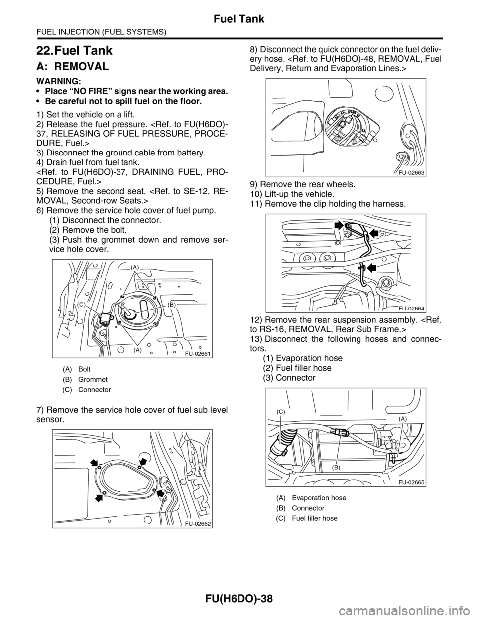
6) Remove the service hole cover of fuel pump.
(1) Disconnect the connector.
(2) Remove the bolt.
(3) Push the grommet down and remove ser-
vice hole cover.
7) Remove the service hole cover of fuel sub level
sensor.
8) Disconnect the quick connector on the fuel deliv-
ery hose.
9) Remove the rear wheels.
10) Lift-up the vehicle.
11) Remove the clip holding the harness.
12) Remove the rear suspension assembly.
13) Disconnect the following hoses and connec-
tors.
(1) Evaporation hose
(2) Fuel filler hose
(3) Connector
(A) Bolt
(B) Grommet
(C) Connector
FU-02661(A)
(A)
(B)(C)
FU-02662
(A) Evaporation hose
(B) Connector
(C) Fuel filler hose
FU-02663
FU-02664
FU-02665
(A)
(B)
(C)
Page 1602 of 2453
FU(H6DO)-41
Fuel Filler Pipe
FUEL INJECTION (FUEL SYSTEMS)
23.Fuel Filler Pipe
A: REMOVAL
WARNING:
•Place “NO FIRE” signs near the working area.
•Be careful not to spill fuel on the floor.
1) Disconnect the ground cable from battery.
2) Open the fuel filler flap lid, and remove the filler
cap.
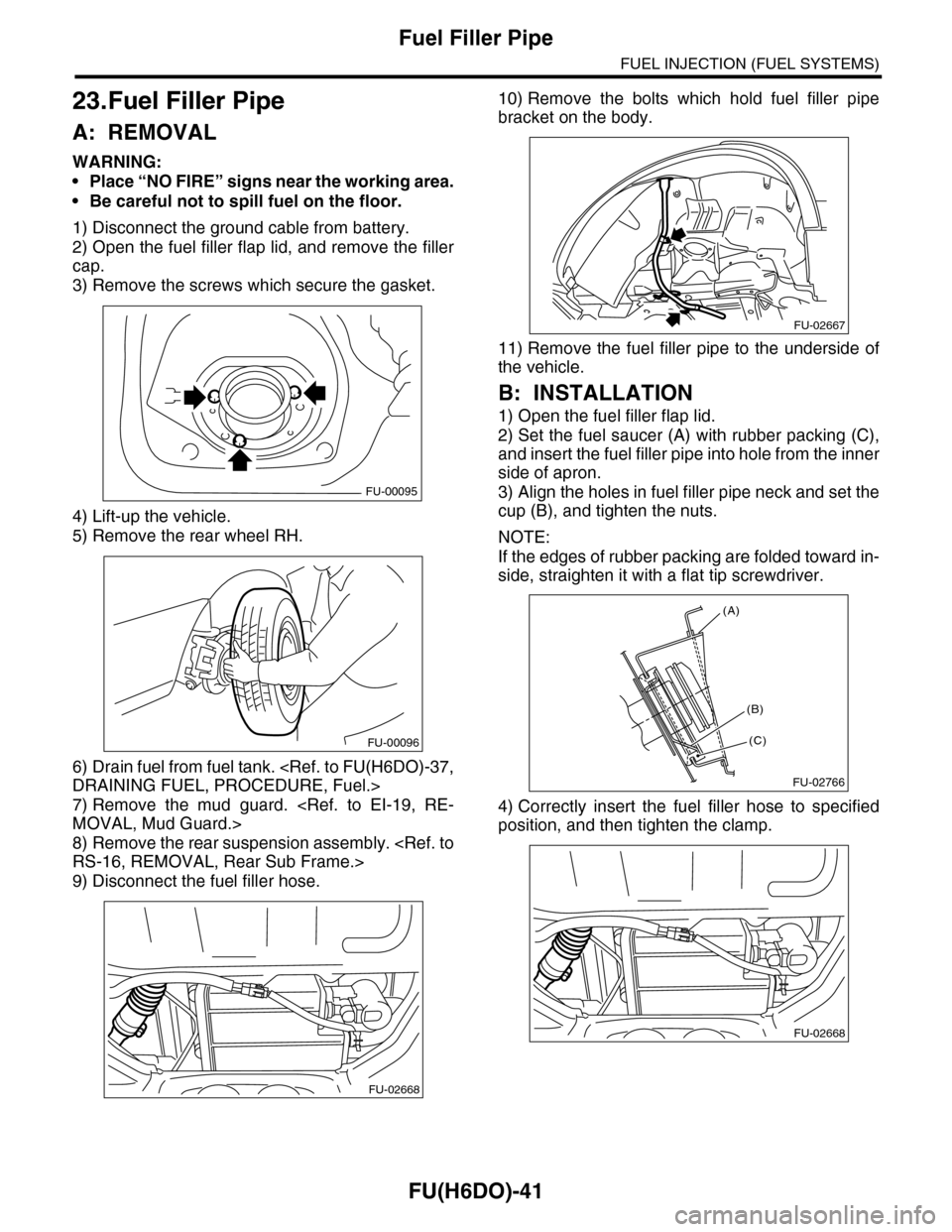
3) Remove the screws which secure the gasket.
4) Lift-up the vehicle.
5) Remove the rear wheel RH.
6) Drain fuel from fuel tank.
7) Remove the mud guard.
8) Remove the rear suspension assembly.
9) Disconnect the fuel filler hose.
10) Remove the bolts which hold fuel filler pipe
bracket on the body.
11) Remove the fuel filler pipe to the underside of
the vehicle.
B: INSTALLATION
1) Open the fuel filler flap lid.
2) Set the fuel saucer (A) with rubber packing (C),
and insert the fuel filler pipe into hole from the inner
side of apron.
3) Align the holes in fuel filler pipe neck and set the
cup (B), and tighten the nuts.
NOTE:
If the edges of rubber packing are folded toward in-
side, straighten it with a flat tip screwdriver.
4) Correctly insert the fuel filler hose to specified
position, and then tighten the clamp.
FU-00095
FU-00096
FU-02668
FU-02667
FU-02766
(A)
(C)
(B)
FU-02668
Page 1607 of 2453
FU(H6DO)-46
Fuel Sub Level Sensor
FUEL INJECTION (FUEL SYSTEMS)
26.Fuel Sub Level Sensor
A: REMOVAL
WARNING:
•Place “NO FIRE” signs near the working area.
•Be careful not to spill fuel on the floor.
1) Drain fuel.
2) Remove the second seat.
3) Remove the service hole cover.
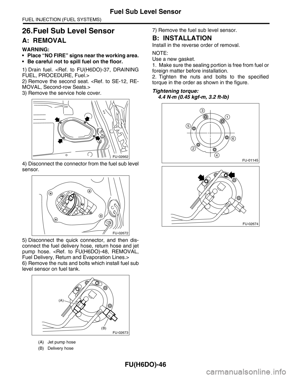
4) Disconnect the connector from the fuel sub level
sensor.
5) Disconnect the quick connector, and then dis-
connect the fuel delivery hose, return hose and jet
pump hose.
6) Remove the nuts and bolts which install fuel sub
level sensor on fuel tank.
7) Remove the fuel sub level sensor.
B: INSTALLATION
Install in the reverse order of removal.
NOTE:
Use a new gasket.
1. Make sure the sealing portion is free from fuel or
foreign matter before installation.
2. Tighten the nuts and bolts to the specified
torque in the order as shown in the figure.
Tightening torque:
4.4 N·m (0.45 kgf-m, 3.2 ft-lb)
(A) Jet pump hose
(B) Delivery hose
FU-02662
FU-02672
FU-02673(B)
(A)
FU-01145
1
6
5
2
4
3
FU-02674
Page 1853 of 2453
LU(H6DO)-4
General Description
LUBRICATION
C: CAUTION
•Wear work clothing, including a cap, protective goggles and protective shoes during operation.
•Remove contamination including dirt and corrosion before removal, installation or disassembly.
•Keep the disassembled parts in order and protect them from dust and dirt.
•Before removal, installation or disassembly, be sure to clarify the failure. Avoid unnecessary removal, in-
stallation, disassembly and replacement.
•Be careful not to burn yourself, because each part on the vehicle is hot after running.
•Be sure to tighten fasteners including bolts and nuts to the specified torque.
•Place shop jacks or rigid racks at the specified points.
•Before disconnecting connectors of sensors or units, be sure to disconnect the ground cable from battery.
D: PREPARATION TOOL
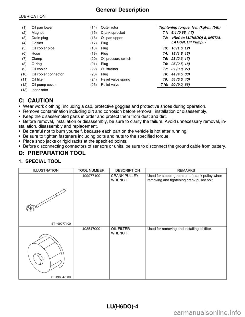
1. SPECIAL TOOL
(1) Oil pan lower (14) Outer rotorTightening torque: N·m (kgf-m, ft-lb)
(2) Magnet (15) Crank sprocketT1: 6.4 (0.65, 4.7)
(3) Drain plug (16) Oil pan upperT2:
(5) Oil cooler pipe (18) PlugT3: 16 (1.6, 12)
(6) Hose (19) PlugT4: 18 (1.8, 13)
(7) Clamp (20) Oil pressure switchT5: 23 (2.3, 17)
(8) O-ring (21) PlugT6: 25 (2.5, 18)
(9) Oil cooler (22) Oil strainerT7: 37 (3.8, 27)
(10) Oil cooler connector (23) PlugT8: 44 (4.5, 33)
(11) Oil filter (24) Relief valve springT9: 54 (5.5, 40)
(12) Oil pump cover (25) Relief valveT10: 90 (9.2, 66)
(13) Inner rotor
ILLUSTRATION TOOL NUMBER DESCRIPTION REMARKS
499977100 CRANK PULLEY
WRENCH
Used for stopping rotation of crank pulley when
removing and tightening crank pulley bolt.
498547000 OIL FILTER
WRENCH
Used for removing and installing oil filter.
ST-499977100
ST-498547000
Page 1857 of 2453
LU(H6DO)-8
Oil Pump
LUBRICATION
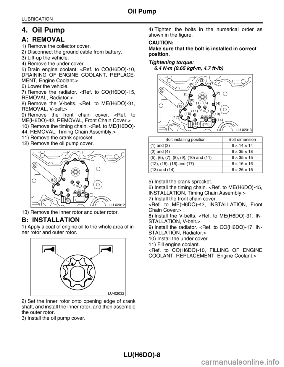
4. Oil Pump
A: REMOVAL
1) Remove the collector cover.
2) Disconnect the ground cable from battery.
3) Lift-up the vehicle.
4) Remove the under cover.
5) Drain engine coolant.
MENT, Engine Coolant.>
6) Lower the vehicle.
7) Remove the radiator.
8) Remove the V-belts.
9) Remove the front chain cover.
10) Remove the timing chain.
11) Remove the crank sprocket.
12) Remove the oil pump cover.
13) Remove the inner rotor and outer rotor.
B: INSTALLATION
1) Apply a coat of engine oil to the whole area of in-
ner rotor and outer rotor.
2) Set the inner rotor onto opening edge of crank
shaft, and install the inner rotor, and then assemble
the outer rotor.
3) Install the oil pump cover.
4) Tighten the bolts in the numerical order as
shown in the figure.
CAUTION:
Make sure that the bolt is installed in correct
position.
Tightening torque:
6.4 N·m (0.65 kgf-m, 4.7 ft-lb)
5) Install the crank sprocket.
6) Install the timing chain.
7) Install the front chain cover.
8) Install the V-belts.
9) Install the radiator.
10) Install the under cover.
11) Fill engine coolant.
LU-02012
LU-02032
Bolt installing position Bolt dimension
(1) and (3) 6 × 14 × 14
(2) and (4) 6 × 35 × 18
(5), (6), (7), (8), (9), (10) and (11) 6 × 35 × 15
(12), (15), (16) and (17) 6 × 16 × 16
(13) and (14) 6 × 26 × 15
LU-02013
(3)(7)
(2)
(4)
(9)
(5)
(8)(1)(6)(12)
(13)(14)(15)
(16)(17)
(11)(10)
Page 1864 of 2453
LU(H6DO)-15
Oil Cooler
LUBRICATION
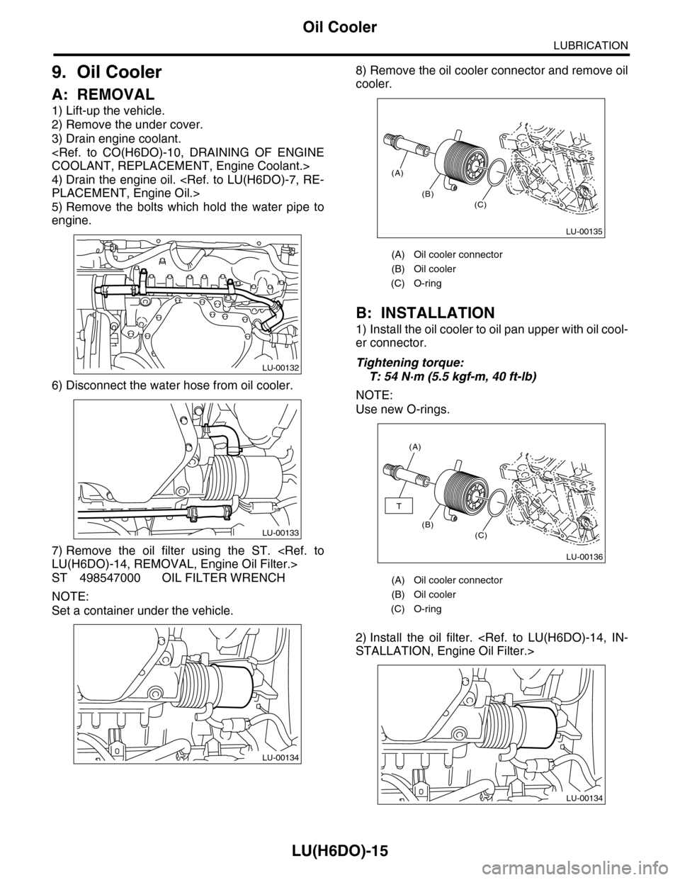
9. Oil Cooler
A: REMOVAL
1) Lift-up the vehicle.
2) Remove the under cover.
3) Drain engine coolant.
4) Drain the engine oil.
5) Remove the bolts which hold the water pipe to
engine.
6) Disconnect the water hose from oil cooler.
7) Remove the oil filter using the ST.
ST 498547000 OIL FILTER WRENCH
NOTE:
Set a container under the vehicle.
8) Remove the oil cooler connector and remove oil
cooler.
B: INSTALLATION
1) Install the oil cooler to oil pan upper with oil cool-
er connector.
Tightening torque:
T: 54 N·m (5.5 kgf-m, 40 ft-lb)
NOTE:
Use new O-rings.
2) Install the oil filter.
LU-00132
LU-00133
LU-00134
(A) Oil cooler connector
(B) Oil cooler
(C) O-ring
(A) Oil cooler connector
(B) Oil cooler
(C) O-ring
(A)
(B)(C)
LU-00135
(A)
(B)(C)
T
LU-00136
LU-00134
Page 1928 of 2453
ME(H6DO)-62
Cylinder Block
MECHANICAL
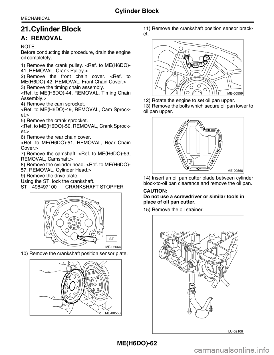
21.Cylinder Block
A: REMOVAL
NOTE:
Before conducting this procedure, drain the engine
oil completely.
1) Remove the crank pulley.
2) Remove the front chain cover.
3) Remove the timing chain assembly.
4) Remove the cam sprocket.
5) Remove the crank sprocket.
6) Remove the rear chain cover.
7) Remove the camshaft.
8) Remove the cylinder head.
9) Remove the drive plate.
Using the ST, lock the crankshaft.
ST 498497100 CRANKSHAFT STOPPER
10) Remove the crankshaft position sensor plate.
11) Remove the crankshaft position sensor brack-
et.
12) Rotate the engine to set oil pan upper.
13) Remove the bolts which secure oil pan lower to
oil pan upper.
14) Insert an oil pan cutter blade between cylinder
block-to-oil pan clearance and remove the oil pan.
CAUTION:
Do not use a screwdriver or similar tools in
place of oil pan cutter.
15) Remove the oil strainer.
ME-02664
ST
ME-00558
ME-00559
ME-00560
LU-02108
Page 1954 of 2453
ME(H6DO)-88
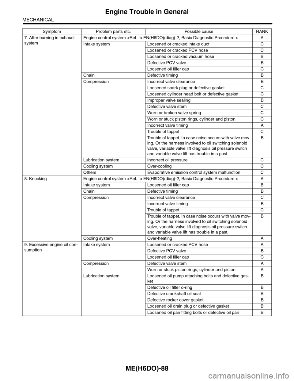
Engine Trouble in General
MECHANICAL
7. After burning in exhaust
system
Engine control system
Intake system Loosened or cracked intake duct C
Loosened or cracked PCV hose C
Loosened or cracked vacuum hose B
Defective PCV valve B
Loosened oil filler cap C
Chain Defective timing B
Compression Incorrect valve clearance B
Loosened spark plug or defective gasket C
Loosened cylinder head bolt or defective gasket C
Improper valve sealing B
Defective valve stem C
Wor n or broken valve spr ing C
Wor n or stuck piston r ings, cylinder and piston C
Incorrect valve timing A
Tr o u b l e o f t a p p e t C
Tr o u b l e o f t a p p e t . I n c a s e n o i s e o c c u r s w i t h v a l v e m o v -
ing. Or the harness involved to oil switching solenoid
valve, variable valve lift diagnosis oil pressure switch
and variable valve lift has trouble in a past.
B
Lubrication system Incorrect oil pressure C
Cooling system Over-cooling C
Others Evaporative emission control system malfunction C
8. Knocking Engine control system
Intake system Loosened oil filler cap B
Chain Defective timing B
Compression Incorrect valve clearance C
Incorrect valve timing B
Tr o u b l e o f t a p p e t C
Tr o u b l e o f t a p p e t . I n c a s e n o i s e o c c u r s w i t h v a l v e m o v -
ing. Or the harness involved to oil switching solenoid
valve, variable valve lift diagnosis oil pressure switch
and variable valve lift has trouble in a past.
B
Cooling system Over-heating A
9. Excessive engine oil con-
sumption
Intake system Loosened or cracked PCV hose A
Defective PCV valve B
Loosened oil filler cap C
Compression Defective valve stem A
Wor n or stuck piston r ings, cylinder and piston A
Lubrication system Loosened oil pump attaching bolts and defective gas-
ket
B
Defective oil filter o-ring B
Defective crankshaft oil seal B
Defective rocker cover gasket B
Loosened oil drain plug or defective gasket B
Loosened oil pan fitting bolts or defective oil pan B
Symptom Problem parts etc. Possible cause RANK