Page 2013 of 2453

PM-30
Steering System (Power Steering)
PERIODIC MAINTENANCE SERVICES
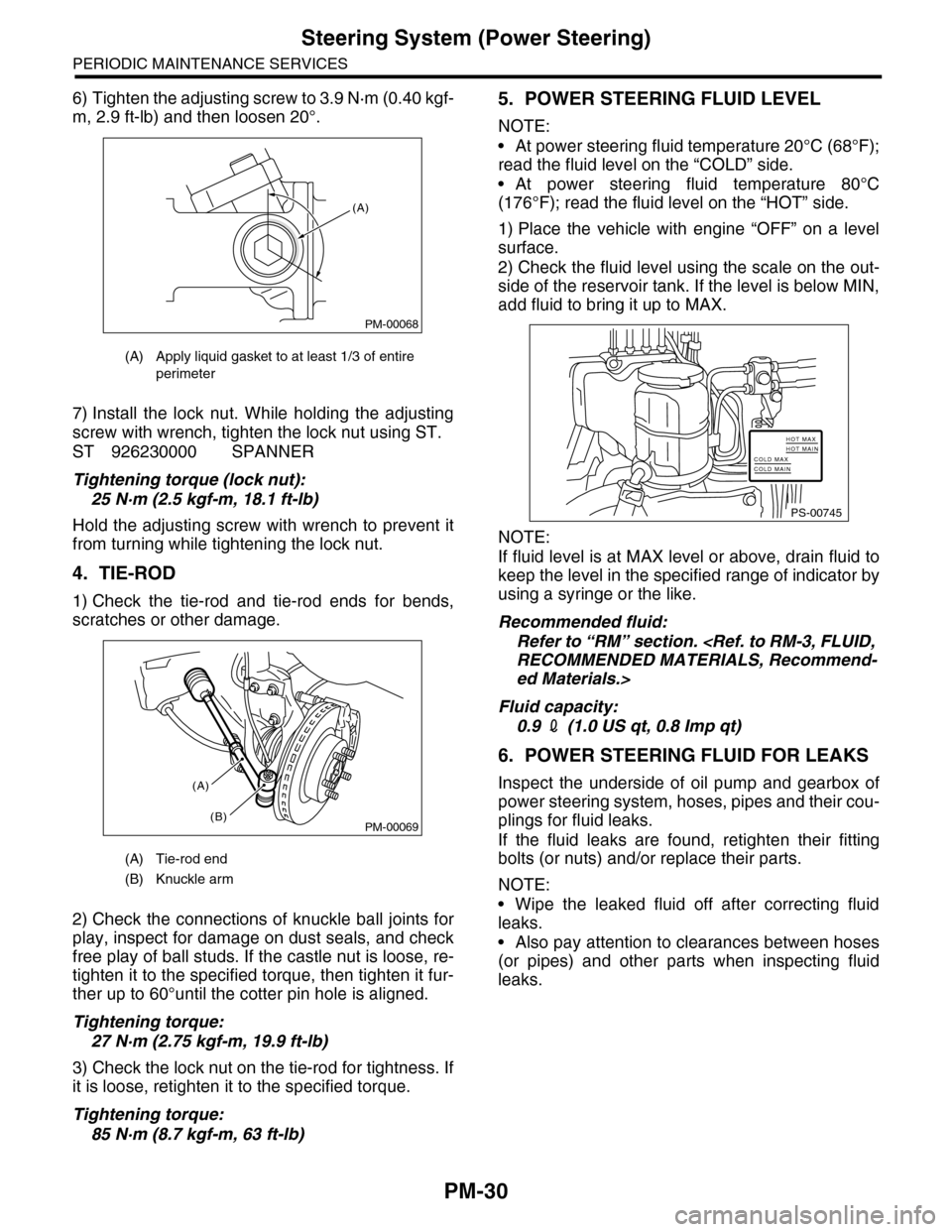
6) Tighten the adjusting screw to 3.9 N·m (0.40 kgf-
m, 2.9 ft-lb) and then loosen 20°.
7) Install the lock nut. While holding the adjusting
screw with wrench, tighten the lock nut using ST.
ST 926230000 SPANNER
Tightening torque (lock nut):
25 N·m (2.5 kgf-m, 18.1 ft-lb)
Hold the adjusting screw with wrench to prevent it
from turning while tightening the lock nut.
4. TIE-ROD
1) Check the tie-rod and tie-rod ends for bends,
scratches or other damage.
2) Check the connections of knuckle ball joints for
play, inspect for damage on dust seals, and check
free play of ball studs. If the castle nut is loose, re-
tighten it to the specified torque, then tighten it fur-
ther up to 60°until the cotter pin hole is aligned.
Tightening torque:
27 N·m (2.75 kgf-m, 19.9 ft-lb)
3) Check the lock nut on the tie-rod for tightness. If
it is loose, retighten it to the specified torque.
Tightening torque:
85 N·m (8.7 kgf-m, 63 ft-lb)
5. POWER STEERING FLUID LEVEL
NOTE:
•At power steering fluid temperature 20°C (68°F);
read the fluid level on the “COLD” side.
•At power steering fluid temperature 80°C
(176°F); read the fluid level on the “HOT” side.
1) Place the vehicle with engine “OFF” on a level
surface.
2) Check the fluid level using the scale on the out-
side of the reservoir tank. If the level is below MIN,
add fluid to bring it up to MAX.
NOTE:
If fluid level is at MAX level or above, drain fluid to
keep the level in the specified range of indicator by
using a syringe or the like.
Recommended fluid:
Refer to “RM” section.
RECOMMENDED MATERIALS, Recommend-
ed Materials.>
Fluid capacity:
0.9 2 (1.0 US qt, 0.8 Imp qt)
6. POWER STEERING FLUID FOR LEAKS
Inspect the underside of oil pump and gearbox of
power steering system, hoses, pipes and their cou-
plings for fluid leaks.
If the fluid leaks are found, retighten their fitting
bolts (or nuts) and/or replace their parts.
NOTE:
•Wipe the leaked fluid off after correcting fluid
leaks.
•Also pay attention to clearances between hoses
(or pipes) and other parts when inspecting fluid
leaks.
(A) Apply liquid gasket to at least 1/3 of entire
perimeter
(A) Tie-rod end
(B) Knuckle arm
PM-00068
(A)
PM-00069
(A)
(B)
PS-00745
HOT MAXHOT MAINCOLD MAXCOLD MAIN
Page 2051 of 2453
5AT-35
Automatic Transmission Assembly
AUTOMATIC TRANSMISSION
15) Remove the pitching stopper bracket.
16) Set the ST.
ST1 41099AA010 ENGINE SUPPORT BRACK-
ET
ST2 41099AA020 ENGINE SUPPORT
17) Remove the transmission mounting bolt (upper
side).
18) Lift-up the vehicle.
19) Remove the under cover.
20) Remove the front exhaust pipe, rear exhaust
pipe and muffler.
AL, Front Exhaust Pipe.>
REMOVAL, Rear Exhaust Pipe.>
EX(H6DO)-8, REMOVAL, Muffler.>
21) Remove the heat shield cover.
22) Remove the ATF drain plug to drain ATF.
23) Remove the oil charge pipe.
24) Disconnect the connector from turbine speed
sensor 1.
AT-03241
AT-03242
ST2
ST1
AT-03237
(A) Oil pan
(B) Drain plug
AT-03243
(A)
AT-01361
(B)
AT-01371
AT-01642
Page 2065 of 2453

5AT-49
Rear Vehicle Speed Sensor
AUTOMATIC TRANSMISSION
15.Rear Vehicle Speed Sensor
A: REMOVAL
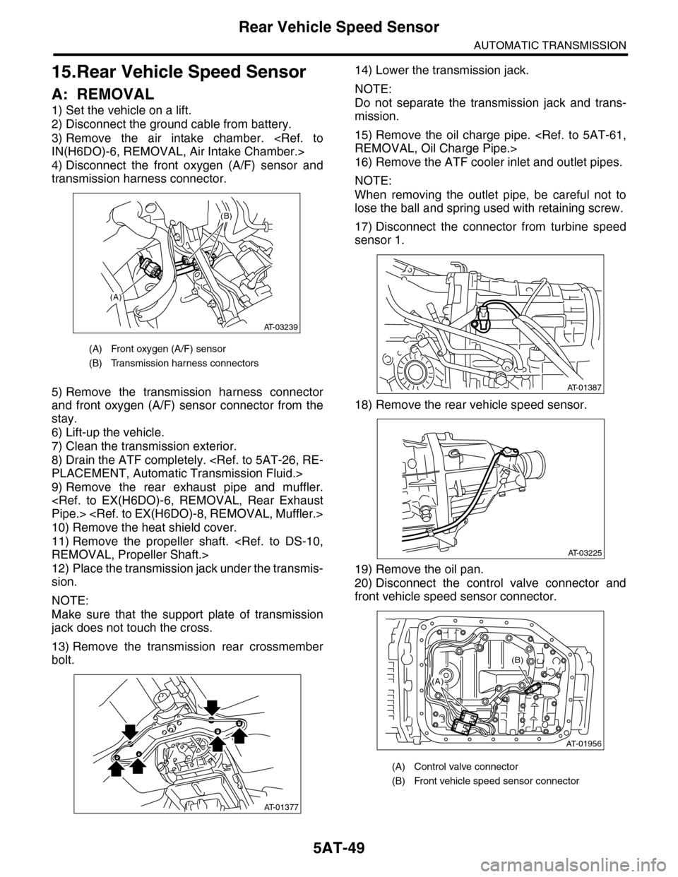
1) Set the vehicle on a lift.
2) Disconnect the ground cable from battery.
3) Remove the air intake chamber.
IN(H6DO)-6, REMOVAL, Air Intake Chamber.>
4) Disconnect the front oxygen (A/F) sensor and
transmission harness connector.
5) Remove the transmission harness connector
and front oxygen (A/F) sensor connector from the
stay.
6) Lift-up the vehicle.
7) Clean the transmission exterior.
8) Drain the ATF completely.
PLACEMENT, Automatic Transmission Fluid.>
9) Remove the rear exhaust pipe and muffler.
Pipe.>
10) Remove the heat shield cover.
11) Remove the propeller shaft.
REMOVAL, Propeller Shaft.>
12) Place the transmission jack under the transmis-
sion.
NOTE:
Make sure that the support plate of transmission
jack does not touch the cross.
13) Remove the transmission rear crossmember
bolt.
14) Lower the transmission jack.
NOTE:
Do not separate the transmission jack and trans-
mission.
15) Remove the oil charge pipe.
REMOVAL, Oil Charge Pipe.>
16) Remove the ATF cooler inlet and outlet pipes.
NOTE:
When removing the outlet pipe, be careful not to
lose the ball and spring used with retaining screw.
17) Disconnect the connector from turbine speed
sensor 1.
18) Remove the rear vehicle speed sensor.
19) Remove the oil pan.
20) Disconnect the control valve connector and
front vehicle speed sensor connector.
(A) Front oxygen (A/F) sensor
(B) Transmission harness connectors
(A)
(B)
AT-03239
AT-01377
(A) Control valve connector
(B) Front vehicle speed sensor connector
AT-01387
AT-03225
AT-01956
(B)
(A)
Page 2069 of 2453

5AT-53
Control Valve Body
AUTOMATIC TRANSMISSION
17.Control Valve Body
A: REMOVAL
1) Set the vehicle on a lift.
2) Disconnect the ground cable from battery.
3) Lift-up the vehicle.
4) Clean the transmission exterior.
5) Remove the ATF drain plug to drain ATF.
CAUTION:
Immediately after the vehicle has been running
or after idling for a long time, the ATF will be
hot. Be careful not to burn yourself.
6) Tighten the ATF drain plug.
NOTE:
Use a new gasket.
Tightening torque:
20 N·m (2.0 kgf-m, 14.8 ft-lb)
7) Remove the oil pan.
CAUTION:
Be sure to prevent the entering of dust and oth-
er foreign matters into oil pan.
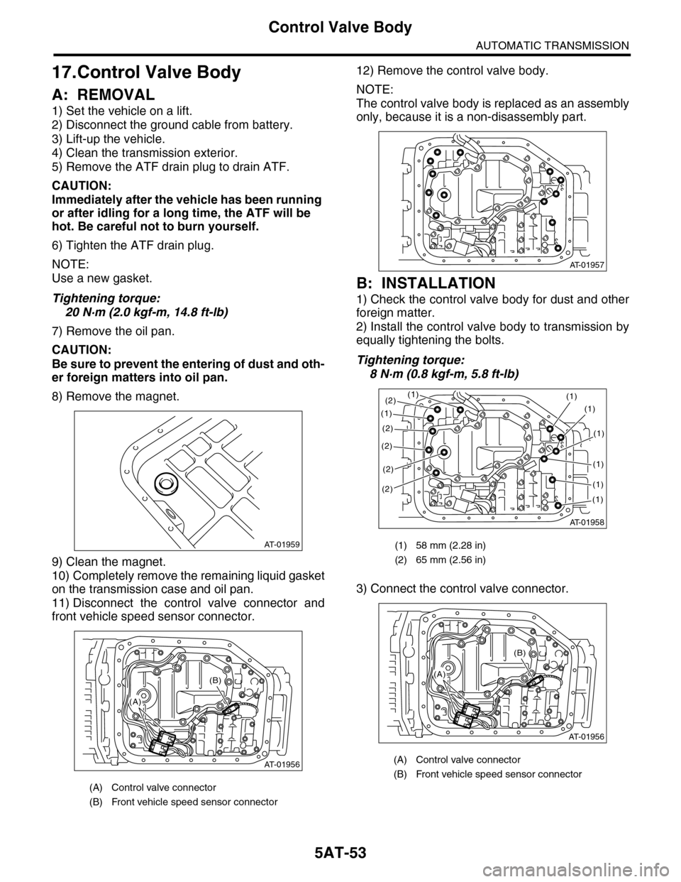
8) Remove the magnet.
9) Clean the magnet.
10) Completely remove the remaining liquid gasket
on the transmission case and oil pan.
11) Disconnect the control valve connector and
front vehicle speed sensor connector.
12) Remove the control valve body.
NOTE:
The control valve body is replaced as an assembly
only, because it is a non-disassembly part.
B: INSTALLATION
1) Check the control valve body for dust and other
foreign matter.
2) Install the control valve body to transmission by
equally tightening the bolts.
Tightening torque:
8 N·m (0.8 kgf-m, 5.8 ft-lb)
3) Connect the control valve connector.
(A) Control valve connector
(B) Front vehicle speed sensor connector
AT-01959
AT-01956
(B)
(A)
(1) 58 mm (2.28 in)
(2) 65 mm (2.56 in)
(A) Control valve connector
(B) Front vehicle speed sensor connector
AT-01957
AT-01958
(1)(1)
(1)
(2)
(2)
(2)
(2)
(1)
(1)
(1)
(1)
(1)
(2)
AT-01956
(B)
(A)
Page 2070 of 2453

5AT-54
Control Valve Body
AUTOMATIC TRANSMISSION
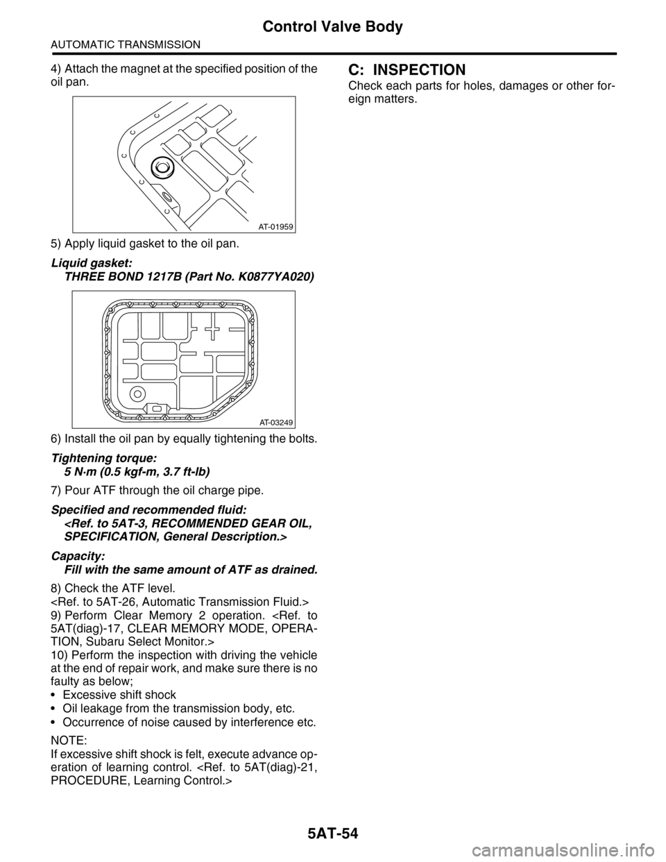
4) Attach the magnet at the specified position of the
oil pan.
5) Apply liquid gasket to the oil pan.
Liquid gasket:
THREE BOND 1217B (Part No. K0877YA020)
6) Install the oil pan by equally tightening the bolts.
Tightening torque:
5 N·m (0.5 kgf-m, 3.7 ft-lb)
7) Pour ATF through the oil charge pipe.
Specified and recommended fluid:
SPECIFICATION, General Description.>
Capacity:
Fill with the same amount of ATF as drained.
8) Check the ATF level.
9) Perform Clear Memory 2 operation.
5AT(diag)-17, CLEAR MEMORY MODE, OPERA-
TION, Subaru Select Monitor.>
10) Perform the inspection with driving the vehicle
at the end of repair work, and make sure there is no
faulty as below;
•Excessive shift shock
•Oil leakage from the transmission body, etc.
•Occurrence of noise caused by interference etc.
NOTE:
If excessive shift shock is felt, execute advance op-
eration of learning control.
PROCEDURE, Learning Control.>
C: INSPECTION
Check each parts for holes, damages or other for-
eign matters.
AT-01959
AT-03249
Page:
< prev 1-8 9-16 17-24