2009 SUBARU TRIBECA radio antenna
[x] Cancel search: radio antennaPage 1036 of 2453

VDC(diag)-44
Diagnostic Procedure with Diagnostic Trouble Code (DTC)
VEHICLE DYNAMICS CONTROL (VDC) (DIAGNOSTICS)
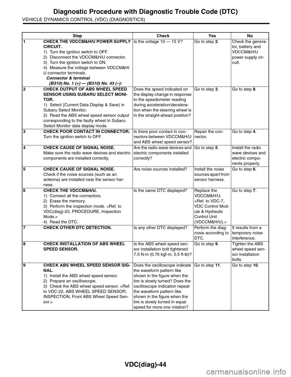
Step Check Yes No
1CHECK THE VDCCM&H/U POWER SUPPLY
CIRCUIT.
1) Turn the ignition switch to OFF.
2) Disconnect the VDCCM&H/U connector.
3) Turn the ignition switch to ON.
4) Measure the voltage between VDCCM&H/
U connector terminals.
Connector & terminal
(B310) No. 1 (+) — (B310) No. 43 (–):
Is the voltage 10 — 15 V? Go to step 2.Check the genera-
tor, batter y and
VDCCM&H/U
power supply cir-
cuit.
2CHECK OUTPUT OF ABS WHEEL SPEED
SENSOR USING SUBARU SELECT MONI-
TOR.
1) Select {Current Data Display & Save} in
Subaru Select Monitor.
2) Read the ABS wheel speed sensor output
corresponding to the faulty wheel in Subaru
Select Monitor data display mode.
Does the speed indicated on
the display change in response
to the speedometer reading
during acceleration/decelera-
tion when the steering wheel is
in the straight-ahead position?
Go to step 3.Go to step 8.
3CHECK POOR CONTACT IN CONNECTOR.
Tu r n t h e i g n i t i o n s w i t c h t o O F F.
Is there poor contact in con-
nectors between VDCCM&H/U
and ABS wheel speed sensor?
Repair the con-
nector.
Go to step 4.
4CHECK CAUSE OF SIGNAL NOISE.
Make sure the radio wave devices and electric
components are installed correctly.
Are the radio wave devices and
electric components installed
correctly?
Go to step 5.Install the radio
wave devices and
electric compo-
nents properly.
5CHECK CAUSE OF SIGNAL NOISE.
Check if the noise sources (such as an
antenna) are installed near the sensor har-
ness.
Are noise sources installed? Install the noise
sources apart from
sensor harness.
Go to step 6.
6CHECK THE VDCCM&H/U.
1) Connect all the connectors.
2) Erase the memory.
3) Perform the inspection mode.
Mode.>
4) Read the DTC.
Is the same DTC displayed? Replace the
VDCCM&H/U.
ule & Hydraulic
Control Unit
(VDCCM&H/U).>
Go to step 7.
7CHECK OTHER DTC DETECTION.Is any other DTC displayed? Perform the diag-
nosis according to
DTC.
It results from a
temporary noise
interference.
8CHECK INSTALLATION OF ABS WHEEL
SPEED SENSOR.
Is the ABS wheel speed sen-
sor installation bolt tightened
7.5 N·m (0.76 kgf-m, 5.5 ft-lb)?
Go to step 9.Tighten the ABS
wheel speed sen-
sor installation
bolts.
9CHECK ABS WHEEL SPEED SENSOR SIG-
NAL.
1) Install the ABS wheel speed sensor.
2) Prepare an oscilloscope.
3) Check the ABS wheel speed sensor.
INSPECTION, Front ABS Wheel Speed Sen-
sor.>
Does the oscilloscope indicate
the waveform pattern like
shown in the figure when the
tire is slowly turned? Does the
oscilloscope indication repeat
the waveform pattern like
shown in the figure when the
tire is slowly turned in equal
speed for more one rotation?
Go to step 11.Go to step 10.
Page 1037 of 2453

VDC(diag)-45
Diagnostic Procedure with Diagnostic Trouble Code (DTC)
VEHICLE DYNAMICS CONTROL (VDC) (DIAGNOSTICS)
M: DTC C0031 FRONT INLET SOLENOID VALVE RH MALFUNCTION IN VDC-
CM&H/U
NOTE:
For the diagnostic procedure, refer to DTC C0063 “LINEAR VALVE MALFUNCTION IN VDCCM&H/U”.
N: DTC C0032 FRONT OUTLET SOLENOID VALVE RH MALFUNCTION IN VDC-
CM&H/U
NOTE:
For the diagnostic procedure, refer to DTC C0063 “LINEAR VALVE MALFUNCTION IN VDCCM&H/U”.
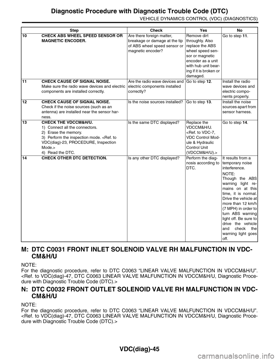
10 CHECK ABS WHEEL SPEED SENSOR OR
MAGNETIC ENCODER.
Are there foreign matter,
breakage or damage at the tip
of ABS wheel speed sensor or
magnetic encoder?
Remove dirt
throughly. Also
replace the ABS
wheel speed sen-
sor or magnetic
encoder as a unit
with hub unit bear-
ing if it is broken or
damaged.
Go to step 11.
11 CHECK CAUSE OF SIGNAL NOISE.
Make sure the radio wave devices and electric
components are installed correctly.
Are the radio wave devices and
electric components installed
correctly?
Go to step 12.Install the radio
wave devices and
electric compo-
nents properly.
12 CHECK CAUSE OF SIGNAL NOISE.
Check if the noise sources (such as an
antenna) are installed near the sensor har-
ness.
Is the noise sources installed? Go to step 13.Install the noise
sources apart from
sensor harness.
13 CHECK THE VDCCM&H/U.
1) Connect all the connectors.
2) Erase the memory.
3) Perform the inspection mode.
Mode.>
4) Read the DTC.
Is the same DTC displayed? Replace the
VDCCM&H/U.
ule & Hydraulic
Control Unit
(VDCCM&H/U).>
Go to step 14.
14 CHECK OTHER DTC DETECTION.Is any other DTC displayed? Perform the diag-
nosis according to
DTC.
It results from a
temporary noise
interference.
NOTE:
Though the ABS
warning light re-
mains on at this
time, it is normal.
Drive the vehicle at
more than 12 km/h
(7 MPH) in order to
turn ABS warning
light off. Be sure to
drive the vehicle
and check the
warning light goes
off.
Step Check Yes No
Page 1166 of 2453

EN(H6DO)(diag)-5
General Description
ENGINE (DIAGNOSTICS)
3. General Description
A: CAUTION
1) Airbag system wiring harness is routed near the
ECM, main relay and fuel pump relay.
CAUTION:
•All airbag system wiring harnesses and con-
nectors are colored yellow. Do not use electri-
cal test equipment on these circuits.
•Be careful not to damage the airbag system
wiring harness when servicing the ECM, TCM,
main relay and fuel pump relay.
2) Never connect the battery in reverse polarity.
•The ECM will be destroyed instantly.
•The fuel injector and other parts will be dam-
aged.
3) Do not disconnect the battery terminals while the
engine is running.
A large counter electromotive force will be generat-
ed in the generator, and this voltage may damage
electronic parts such as ECM etc.
4) Before disconnecting the connectors of each
sensor and ECM, be sure to turn the ignition switch
to OFF. Perform the clear memory mode after con-
necting the connectors.
5) Poor contact has been identified as a primary
cause of this problem. Measure the voltage or re-
sistance of individual sensor or all electrical control
modules using a tapered pin with a diameter of less
than 0.64 mm (0.025 in). Do not insert the pin more
than 5 mm (0.20 in) into the part.
6) Remove the ECM from the located position after
disconnecting two cables on battery.
Otherwise, the ECM may be damaged.
CAUTION:
When replacing the ECM, be careful not to use
the wrong spec. ECM to avoid any damage on
the fuel injection system.
7) Connectors of each sensor in the engine com-
partment and the harness connectors on the en-
gine side and body side are all designed to be
waterproof. Even if the connectors are waterproof,
take care not to allow water to get into them when
washing the vehicle, or when servicing the vehicle
in rainy weather.
8) Use ECM mounting stud bolts as the grounding
point to chassis when measuring voltage and resis-
tance in the passenger compartment.
9) Use the engine ground terminal or engine as-
sembly as the grounding point to chassis when
measuring the voltage and resistance in engine
compartment.
10) Every MFI-related part is a precision part. Do
not drop them.
11) Observe the following cautions when installing
a radio in MFI equipped models.
CAUTION:
•The antenna must be kept as far apart as pos-
sible from control unit. (The ECM is located un-
der the steering column, inside of the
instrument panel lower trim panel.)
•The antenna feeder must be placed as far apart
as possible from the ECM and MFI harness.
•Carefully adjust the antenna for correct
matching.
•When mounting a large power type radio, pay
special attention to the three items mentioned
above.
•Incorrect installation of the radio may affect
the operation of ECM.
12) Release the pressure in the fuel system before
disconnecting the fuel hose. If engine starts during
this operation, run it until it stops.
13) For the model with ABS, the ABS warning light
may illuminate when performing driving test with
jacked-up or lifted-up condition, but this is not a
system malfunction. The reason for this is the
speed difference between the front and rear
wheels. After diagnosis of engine control system,
perform the ABS memory clear procedure of self-
diagnosis function.
B: INSPECTION
Before performing diagnostics, check the following
item which might affect engine problems.
1. BATTERY
1) Measure the battery voltage and specific gravity
of electrolyte.
Standard voltage: 12 V
Specific gravity: Above 1.260
2) Check the condition of the main and other fuses,
and harnesses and connectors. Also check for
proper grounding.
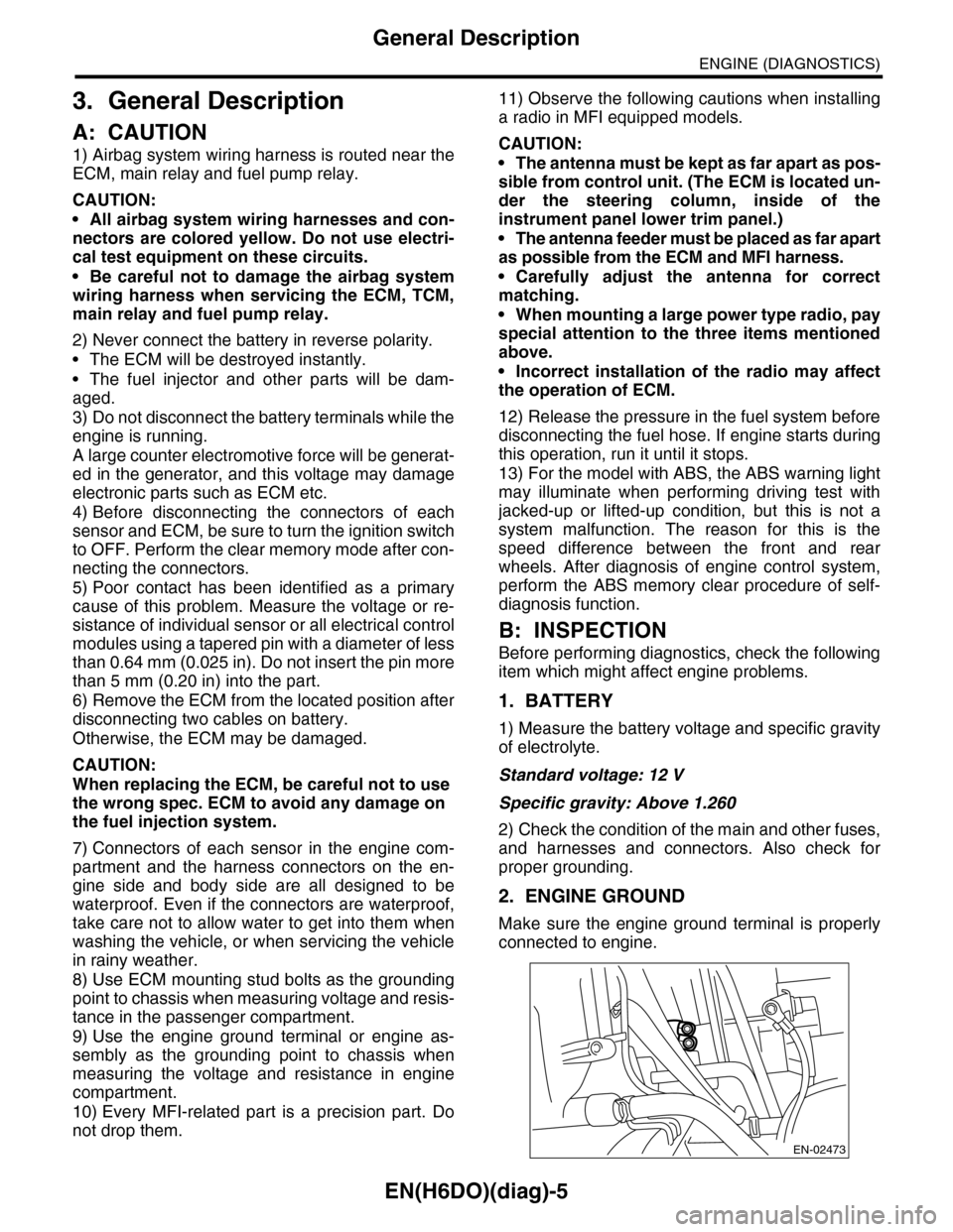
2. ENGINE GROUND
Make sure the engine ground terminal is properly
connected to engine.
EN-02473
Page 2393 of 2453

WI-109
Audio System
WIRING SYSTEM
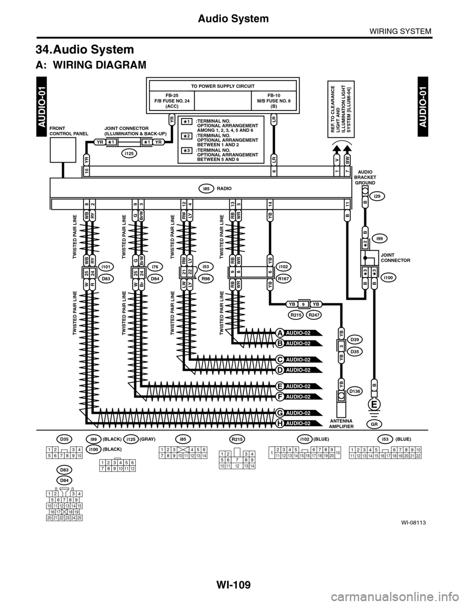
34.Audio System
A: WIRING DIAGRAM
WI-08113
AUDIO-01AUDIO-01
ANTENNAAMPLIFIER
YBD136
LRYR
FB-25F/B FUSE NO. 24(ACC)
FB-10M/B FUSE NO. 8(B)
TO POWER SUPPLY CIRCUIT
RWLY
RWLY
124
RADIOi85
V
1
BW
7
BrW
3
G
9
B
11
YB
14
YR
10AUDIOBRACKETGROUND
Bi29
i53
LWLYR982122
JOINT CONNECTOR(ILLUMINATION & BACK-UP)FRONTCONTROL PANEL
YRYR
i125
LR
6
B
GR
i85
1234567891011121314
D84
567821943
10
2422 23 25
11121314151617181920 21
WBRY
WBRY
82
i101
WR
2524D83
TWISTED PAIR LINETWISTED PAIR LINETWISTED PAIR LINETWISTED PAIR LINE
TWISTED PAIR LINETWISTED PAIR LINETWISTED PAIR LINETWISTED PAIR LINE
RBWR
RBWR
135
i102
RBWR
R16798
YB
YB
6i76
D84WBr
GBrW
2524
REF. TO CLEARANCELIGHT ANDILLUMINATION LIGHTSYSTEM [ILLUMI-04]
D83
1*1*
B
B
B
AUDIO-02H
AUDIO-02G
AUDIO-02F
AUDIO-02E
AUDIO-02D
AUDIO-02C
AUDIO-02B
AUDIO-02A
JOINTCONNECTOR
i100
i99
3*3*
2*
YBYB9
R247R215
D39
D35YB
YB
3
1234567891413121110151617181920
i102(BLUE)
123 8910411 12 13 14 15 16567171819202122
i53(BLUE)D35
12345678910
R215
12
10 115634897131412123456789101112
i125(GRAY)
i100(BLACK)
i99(BLACK)
::TERMINAL NO. OPTIONAL ARRANGEMENT BETWEEN 1 AND 2 ::TERMINAL NO. OPTIONAL ARRANGEMENT BETWEEN 5 AND 6
2*
3*
::TERMINAL NO. OPTIONAL ARRANGEMENT AMONG 1, 2, 3, 4, 5 AND 6
1*