2009 SUBARU TRIBECA service
[x] Cancel search: servicePage 915 of 2453

PS-35
Steering Gearbox
POWER ASSISTED SYSTEM (POWER STEERING)
5. TURNING RESISTANCE OF GEARBOX
Using the ST, measure the gearbox turning resis-
tance.
ST 34099PA100 SPANNER
Service limit:
Maximum allowable resistance:
10.5 N (1.1 kgf, 2.4 lb) or less
Difference between right and left turning re-
sistance:
20% or less
6. OIL LEAKAGE
PS-00105
(1) Power cylinder (3) Rack piston (5) Input shaft
(2) Cylinder (4) Rack axle (6) Valve housing
PS-00622
(4) (3) (2)
(5)
(6)
cd
a
b
(1)
fggd
e
Page 919 of 2453

PS-39
Pipe Assembly
POWER ASSISTED SYSTEM (POWER STEERING)
C: INSPECTION
Check all disassembled parts for wear, damage or other problems. Repair or replace the defective parts as
necessary.
CAUTION:
Although the surface layer materials of rubber hoses have excellent weathering resistance, heat re-
sistance and resistance for low temperature brittleness, they are likely to be damaged chemically by
brake fluid, battery electrolyte, engine oil and automatic transmission fluid and their service lives are
to be very shortened. Wipe off hoses immediately if any of these come into contact with the hoses.
Since resistances for heat or low temperature brittleness are gradually declining according to time
accumulation of hot or cold conditions for the hoses and their service lives are shortening accord-
ingly, it is necessary to perform careful inspection frequently when the vehicle is used in hot weather
areas, cold weather areas and a driving condition in which many steering operations are required in
short time.
Particularly continuous work of relief valve over 5 seconds causes to reduce service lives of the hos-
es, the oil pump, the fluid, etc. due to over heat.
Par t Maintenance par ts Corrective action
Pipe
•O–ring fitting surface damage
•Nut damage
•Pipe damage
Replace with a new part.
Clamp • Loose clamps Replace with a new part.
Hose
•Flare surface damage
•Flare nut damage
•Outer surface cracks
•Outer surface wear
•Clip damage
•End coupling or adapter for deformation
Replace with a new part.
Tr o u b l e P o s s i b l e c a u s e C o r r e c t i v e a c t i o n
Pressure hose burst
Excessive holding time of relief status Instruct customers.
Malfunction of the relief valve Replace the oil pump.
Poor cold character istic of fluid R eplace fluid.
Disconnection of the return
hose
Improper connection Repair.
Loosening of the clip Retighten.
Poor cold character istic of fluid R eplace fluid.
Fluid slightly leaking out of
hose
Wrong layout, tensioned Replace the hose.
Excessive play of engine due to deterioration of
engine mounting rubberReplace the parts if defective.
Improper stop position of pitching stopper Replace the parts if defective.
Crack on hose
Excessive holding time of relief statusReplace.
Instruct customers.
Excessive tightening torque for return hose clip Replace.
Power steer ing fluid, engine oil, electrolyte adhere
on the hose surface
Replace.
Be careful during service work.
To o m a n y u s e s i n e x t r e m e l y c o l d w e a t h e rReplace.
Instruct customers.
Page 924 of 2453

PS-44
Oil Pump
POWER ASSISTED SYSTEM (POWER STEERING)
E: INSPECTION
1. BASIC INSPECTION
Perform the following inspection procedures and replace faulty parts.
2. SERVICE LIMIT
Make a measurements as follows. If it exceeds the
service limit, replace with a new one.
CAUTION:
•When securing the oil pump on a vise, hold
the oil pump with the least possible force be-
tween two pieces of wood.
•Do not set the outside of flow control valve or
pulley on a vise; otherwise outside or pulley
might be deformed. Select properly sized wood
pieces.
1) Play of the pulley shaft
Condition:
P: When applying the force of 9.8 N (1.0 kgf,
2.2 lb)
Service limit:
Play in the radial direction (Direction )
Less than 0.2 mm (0.008 in)
Axial play (Direction )
Less than 0.6 mm (0.024 in)
2) Deflection of the pulley groove
Service limit:
Less than 1.0 mm (0.039 in)
NOTE:
Read the value for one surface of V ditch, and then
the value for another off the dial.
No. Parts Inspection Corrective action
1Oil pump
(Exterior)
(1) Crack, damage or oil leakage Replace the oil pump with a new one.
(2) Play of pulley shaft
Measure the radial play and axial play.
If any of these exceeds the service limit, replace the oil pump
with a new one.
2Pulley
(1) Damage Replace with a new part.
(2) BendMeasure the V groove deflection.
If it exceeds the service limit, replace the pulley with a new one.
3Oil pump
(Interior)
(1) Faulty or seized of vane pumpCheck the rotating resistance of pulley.
If it exceeds the service limit, replace the oil pump with new one.
(2) Bend in the shaft or damage
to bearing
If the a string is wrapped on the pulley and rotated, and the oil
pump emits a noise that is markedly different in tone and loud-
ness from a sound of a new oil pump, replace the oil pump with
a new one.
4O–ring Cracking or deterioration Replace with a new part.
5Bracket Cracking Replace with a new part.
(1) Dial gauge
PS-00145P
(1)
(1) Dial gauge
(1) Dial gauge
PS-00146P
(1)
PS-00147
Page 925 of 2453
PS-45
Oil Pump
POWER ASSISTED SYSTEM (POWER STEERING)
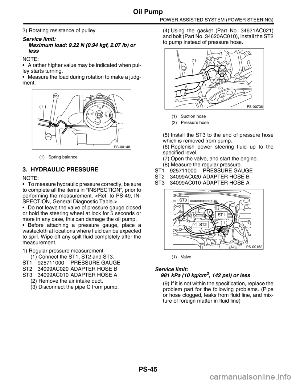
3) Rotating resistance of pulley
Service limit:
Maximum load: 9.22 N (0.94 kgf, 2.07 lb) or
less
NOTE:
•A rather higher value may be indicated when pul-
ley starts turning.
•Measure the load during rotation to make a judg-
ment.
3. HYDRAULIC PRESSURE
NOTE:
•To measure hydraulic pressure correctly, be sure
to complete all the items in “INSPECTION”, prior to
performing the measurement.
•Do not leave the valve of pressure gauge closed
or hold the steering wheel at lock for 5 seconds or
more in any case, this can damage the oil pump.
•Before attaching a pressure gauge, place a
wastecloth at locations where fluid can be expected
to spill. Wipe off any spilt fluid completely after the
measurement.
1) Regular pressure measurement
(1) Connect the ST1, ST2 and ST3.
ST1 925711000 PRESSURE GAUGE
ST2 34099AC020 ADAPTER HOSE B
ST3 34099AC010 ADAPTER HOSE A
(2) Remove the air intake duct.
(3) Disconnect the pipe C from pump.
(4) Using the gasket (Part No. 34621AC021)
and bolt (Part No. 34620AC010), install the ST2
to pump instead of pressure hose.
(5) Install the ST3 to the end of pressure hose
which is removed from pump.
(6) Replenish power steering fluid up to the
specified level.
(7) Open the valve, and start the engine.
(8) Measure the regular pressure.
ST1 925711000 PRESSURE GAUGE
ST2 34099AC020 ADAPTER HOSE B
ST3 34099AC010 ADAPTER HOSE A
Service limit:
981 kPa (10 kg/cm2, 142 psi) or less
(9) If it is not within the specification, replace the
problem part for the following problems. (Pipe
or hose clogged, leaks from fluid line, and mix-
ture of foreign matter in fluid line)
(1) Spring balance
PS-00148
(1) Suction hose
(2) Pressure hose
(1) Valve
PS-00736
(1)
(2)
PS-00152
Page 926 of 2453
PS-46
Oil Pump
POWER ASSISTED SYSTEM (POWER STEERING)
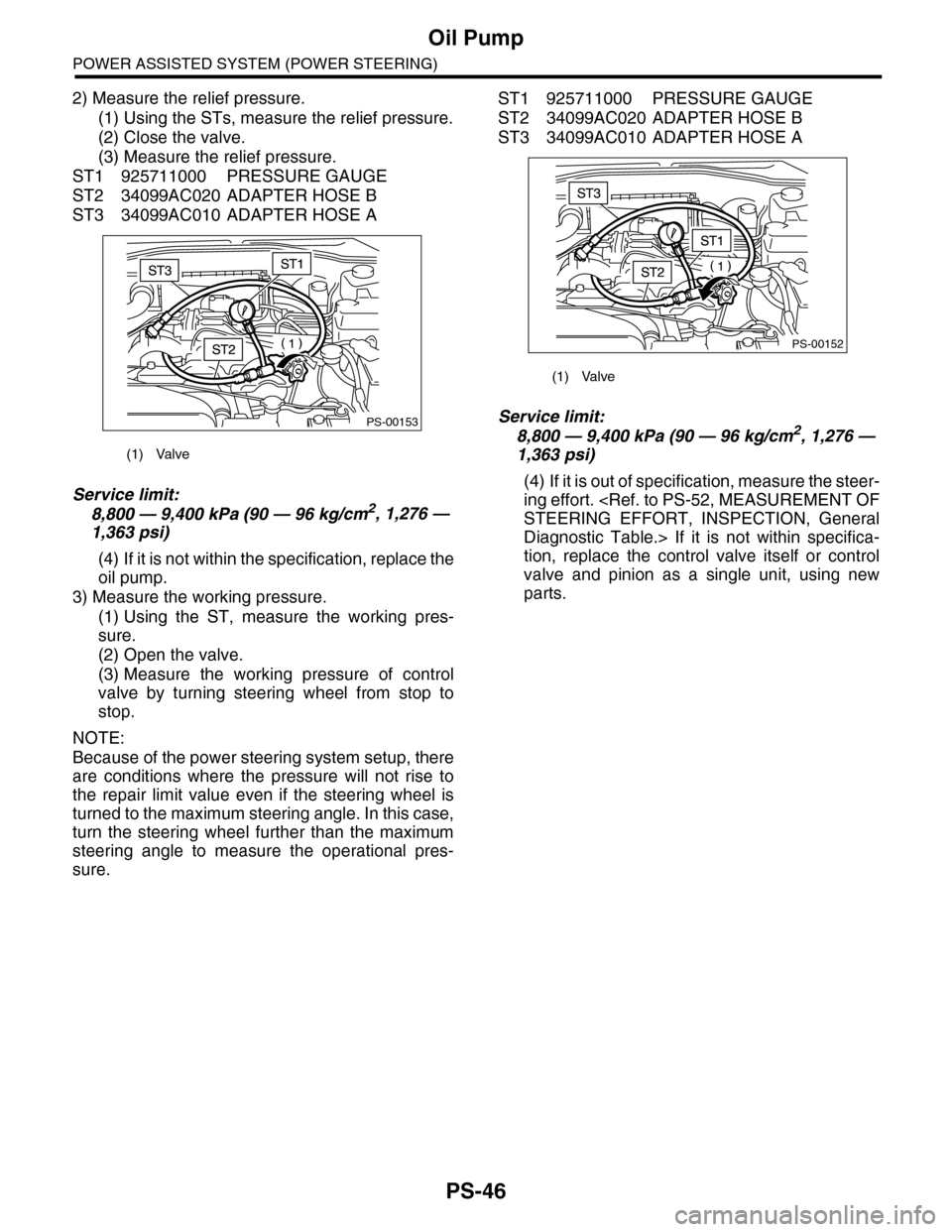
2) Measure the relief pressure.
(1) Using the STs, measure the relief pressure.
(2) Close the valve.
(3) Measure the relief pressure.
ST1 925711000 PRESSURE GAUGE
ST2 34099AC020 ADAPTER HOSE B
ST3 34099AC010 ADAPTER HOSE A
Service limit:
8,800 — 9,400 kPa (90 — 96 kg/cm2, 1,276 —
1,363 psi)
(4) If it is not within the specification, replace the
oil pump.
3) Measure the working pressure.
(1) Using the ST, measure the working pres-
sure.
(2) Open the valve.
(3) Measure the working pressure of control
valve by turning steering wheel from stop to
stop.
NOTE:
Because of the power steering system setup, there
are conditions where the pressure will not rise to
the repair limit value even if the steering wheel is
turned to the maximum steering angle. In this case,
turn the steering wheel further than the maximum
steering angle to measure the operational pres-
sure.
ST1 925711000 PRESSURE GAUGE
ST2 34099AC020 ADAPTER HOSE B
ST3 34099AC010 ADAPTER HOSE A
Service limit:
8,800 — 9,400 kPa (90 — 96 kg/cm2, 1,276 —
1,363 psi)
(4) If it is out of specification, measure the steer-
ing effort.
Diagnostic Table.> If it is not within specifica-
tion, replace the control valve itself or control
valve and pinion as a single unit, using new
parts.
(1) Valve
PS-00153
(1) Valve
PS-00152
Page 1100 of 2453
VDC-19
Steering Angle Sensor
VEHICLE DYNAMICS CONTROL (VDC)
6. Steering Angle Sensor
A: REPLACEMENT
CAUTION:
•Do not perform the removal except when the
replacement.
•When replacing more than three times, re-
place the combination switch as assembly to
protect the threads.
1) Set the steering wheel in a straight-ahead posi-
tion.
2) Disconnect the ground cable from the battery.
3) Remove the airbag module.
WARNING:
Always refer to “Airbag System” when perform-
ing the airbag module repair service.
4) Remove the steering wheel.
5) Remove the screws and remove the steering
column lower cover.
6) Remove the two screws securing the steering
column upper cover.
7) Unlock the harness band and disconnect the
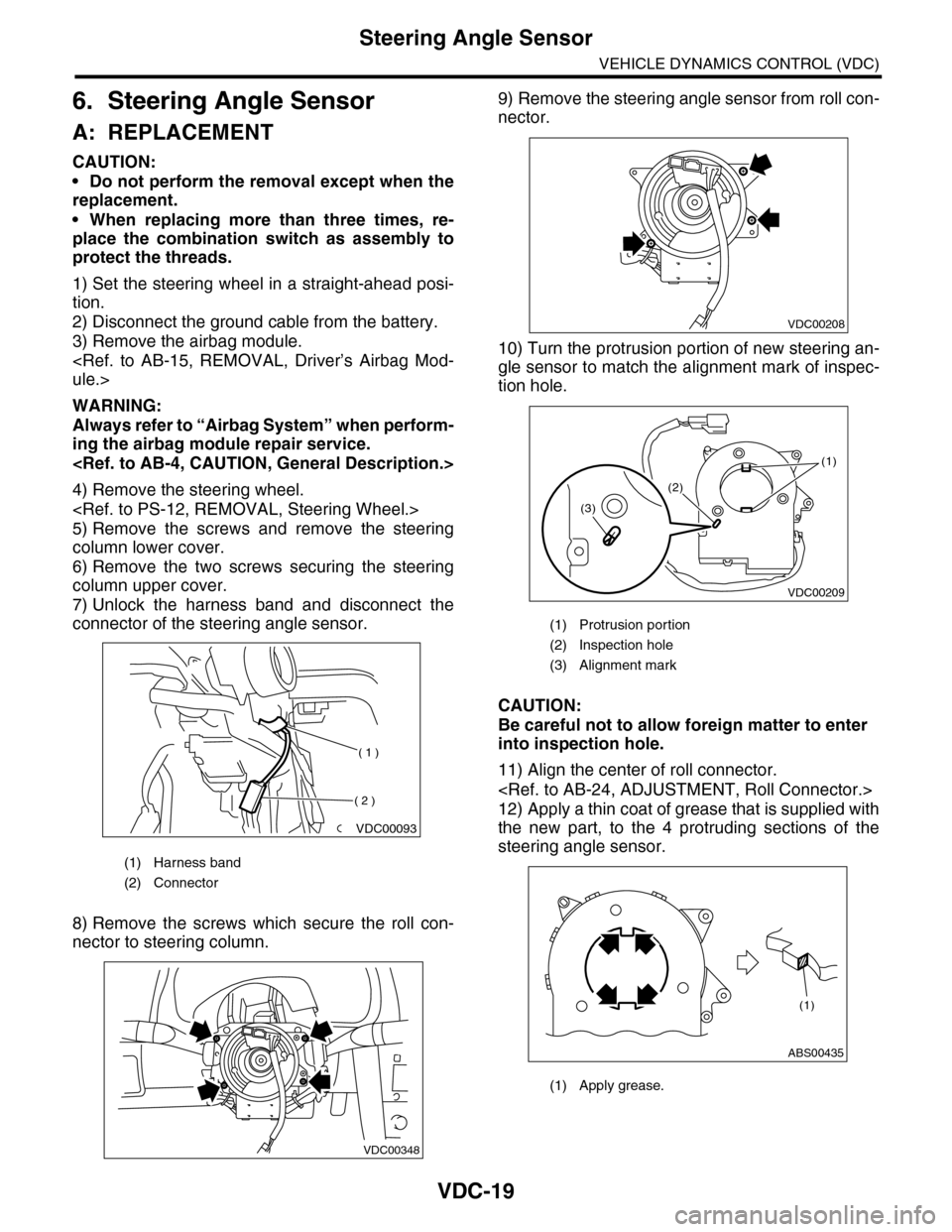
connector of the steering angle sensor.
8) Remove the screws which secure the roll con-
nector to steering column.
9) Remove the steering angle sensor from roll con-
nector.
10) Turn the protrusion portion of new steering an-
gle sensor to match the alignment mark of inspec-
tion hole.
CAUTION:
Be careful not to allow foreign matter to enter
into inspection hole.
11) Align the center of roll connector.
12) Apply a thin coat of grease that is supplied with
the new part, to the 4 protruding sections of the
steering angle sensor.
(1) Harness band
(2) Connector
VDC00093
( 1 )
( 2 )
VDC00348
(1) Protrusion portion
(2) Inspection hole
(3) Alignment mark
(1) Apply grease.
VDC00208
VDC00209
(1)
(2)
(3)
ABS00435
(1)
Page 1101 of 2453
VDC-20
Steering Angle Sensor
VEHICLE DYNAMICS CONTROL (VDC)
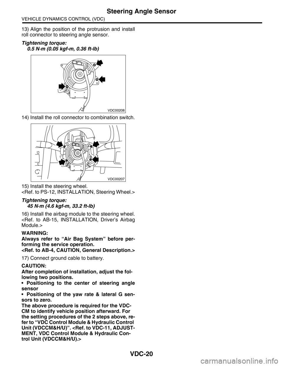
13) Align the position of the protrusion and install
roll connector to steering angle sensor.
Tightening torque:
0.5 N·m (0.05 kgf-m, 0.36 ft-lb)
14) Install the roll connector to combination switch.
15) Install the steering wheel.
Tightening torque:
45 N·m (4.6 kgf-m, 33.2 ft-lb)
16) Install the airbag module to the steering wheel.
WARNING:
Always refer to “Air Bag System” before per-
forming the service operation.
17) Connect ground cable to battery.
CAUTION:
After completion of installation, adjust the fol-
lowing two positions.
•Positioning to the center of steering angle
sensor
•Positioning of the yaw rate & lateral G sen-
sors to zero.
The above procedure is required for the VDC-
CM to identify vehicle position afterward. For
the setting procedures of the 2 steps above, re-
fer to “VDC Control Module & Hydraulic Control
Unit (VDCCM&H/U)”.
trol Unit (VDCCM&H/U).>
VDC00208
VDC00207
Page 1108 of 2453
WT-2
General Description
WHEEL AND TIRE SYSTEM
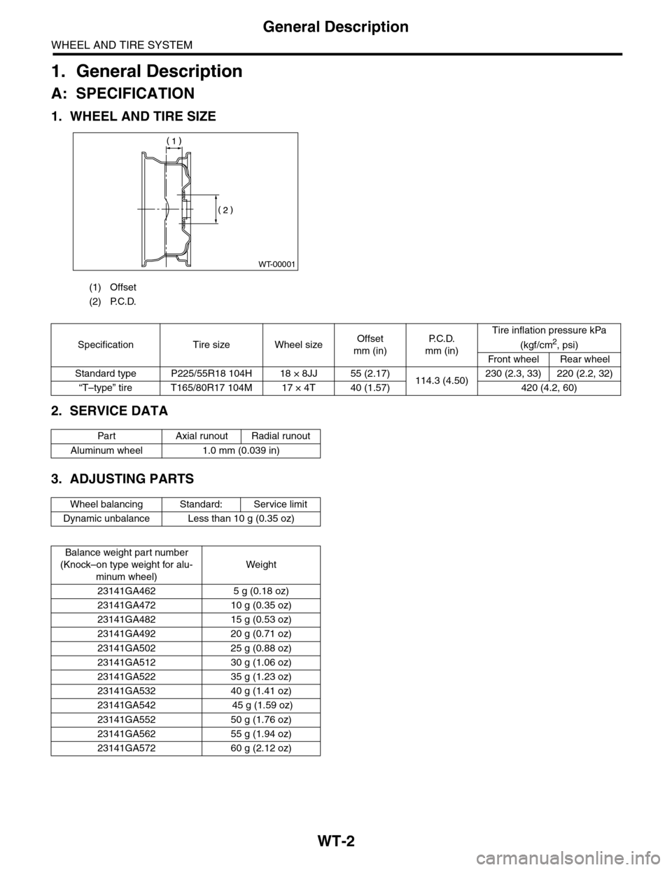
1. General Description
A: SPECIFICATION
1. WHEEL AND TIRE SIZE
2. SERVICE DATA
3. ADJUSTING PARTS
(1) Offset
(2) P.C.D.
WT-00001
Specification Tire size Wheel sizeOffset
mm (in)
P. C . D .
mm (in)
Tire inflation pressure kPa
(kgf/cm2, psi)
Front wheel Rear wheel
Standard type P225/55R18 104H 18 × 8JJ 55 (2.17)114.3 (4.50)230 (2.3, 33) 220 (2.2, 32)
“T–type” tire T165/80R17 104M 17 × 4T 40 (1.57) 420 (4.2, 60)
Par t Axial r unout Radial r unout
Aluminum wheel 1.0 mm (0.039 in)
Wheel balancing Standard: Service limit
Dynamic unbalance Less than 10 g (0.35 oz)
Balance weight par t number
(Knock–on type weight for alu-
minum wheel)
Weight
23141GA462 5 g (0.18 oz)
23141GA472 10 g (0.35 oz)
23141GA482 15 g (0.53 oz)
23141GA492 20 g (0.71 oz)
23141GA502 25 g (0.88 oz)
23141GA512 30 g (1.06 oz)
23141GA522 35 g (1.23 oz)
23141GA532 40 g (1.41 oz)
23141GA542 45 g (1.59 oz)
23141GA552 50 g (1.76 oz)
23141GA562 55 g (1.94 oz)
23141GA572 60 g (2.12 oz)