Page 1880 of 2453
ME(H6DO)-14
General Description
MECHANICAL
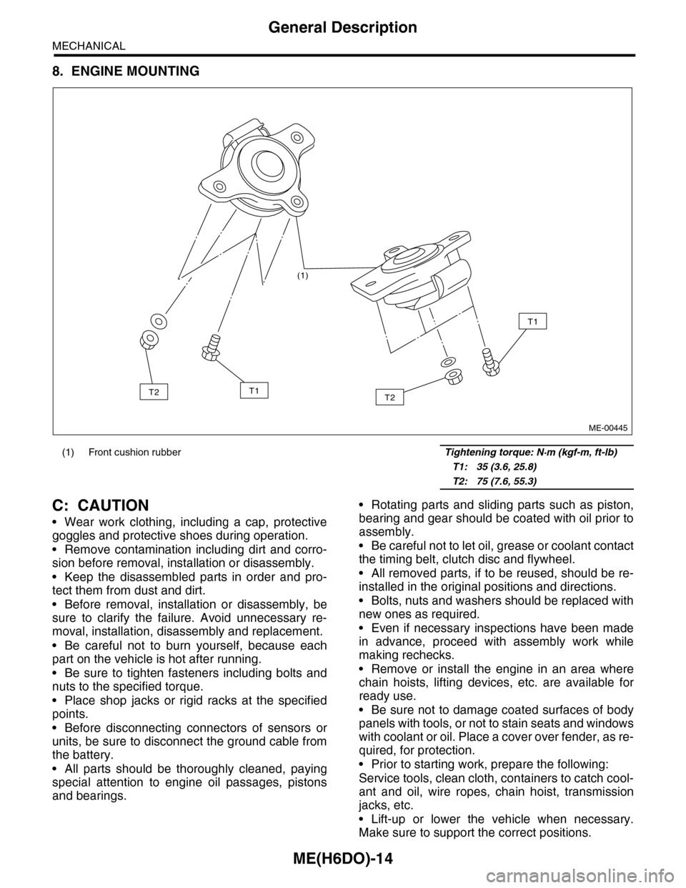
8. ENGINE MOUNTING
C: CAUTION
•Wear work clothing, including a cap, protective
goggles and protective shoes during operation.
•Remove contamination including dirt and corro-
sion before removal, installation or disassembly.
•Keep the disassembled parts in order and pro-
tect them from dust and dirt.
•Before removal, installation or disassembly, be
sure to clarify the failure. Avoid unnecessary re-
moval, installation, disassembly and replacement.
•Be careful not to burn yourself, because each
part on the vehicle is hot after running.
•Be sure to tighten fasteners including bolts and
nuts to the specified torque.
•Place shop jacks or rigid racks at the specified
points.
•Before disconnecting connectors of sensors or
units, be sure to disconnect the ground cable from
the battery.
•All parts should be thoroughly cleaned, paying
special attention to engine oil passages, pistons
and bearings.
•Rotating parts and sliding parts such as piston,
bearing and gear should be coated with oil prior to
assembly.
•Be careful not to let oil, grease or coolant contact
the timing belt, clutch disc and flywheel.
•All removed parts, if to be reused, should be re-
installed in the original positions and directions.
•Bolts, nuts and washers should be replaced with
new ones as required.
•Even if necessary inspections have been made
in advance, proceed with assembly work while
making rechecks.
•Remove or install the engine in an area where
chain hoists, lifting devices, etc. are available for
ready use.
•Be sure not to damage coated surfaces of body
panels with tools, or not to stain seats and windows
with coolant or oil. Place a cover over fender, as re-
quired, for protection.
•Prior to starting work, prepare the following:
Service tools, clean cloth, containers to catch cool-
ant and oil, wire ropes, chain hoist, transmission
jacks, etc.
•Lift-up or lower the vehicle when necessary.
Make sure to support the correct positions.
(1) Front cushion rubber Tightening torque: N·m (kgf-m, ft-lb)
T1: 35 (3.6, 25.8)
T2: 75 (7.6, 55.3)
(1)
T2
T1
T1T2
ME-00445
Page 1886 of 2453
ME(H6DO)-20
General Description
MECHANICAL
2. GENERAL TOOL
E: PROCEDURE
It is possible to conduct the following service procedures with engine on vehicle, however, the procedures
described in this section are based on the condition that the engine is removed from vehicle.
•Camshaft
•Cylinder head
18471AA000 FUEL PIPE
ADAPTER
Used for measuring fuel pressure.
42075AG690 FUEL HOSE Used for measuring fuel pressure.
This is a genuine Subaru part.
TOOL NAME REMARKS
Compression gauge Used for measuring compression.
ILLUSTRATION TOOL NUMBER DESCRIPTION REMARKS
Page 1887 of 2453
ME(H6DO)-21
Compression
MECHANICAL
2. Compression
A: INSPECTION
CAUTION:
After warming-up, engine becomes very hot. Be
careful not to burn yourself during measure-
ment.
1) After warming-up the engine, turn the ignition
switch to OFF.
2) Make sure that the battery is fully charged.
3) Release the fuel pressure.
PRESSURE, PROCEDURE, Fuel.>
4) Remove all the spark plugs.
4, REMOVAL, Spark Plug.>
5) Check the starter motor for satisfactory perfor-
mance and operation.
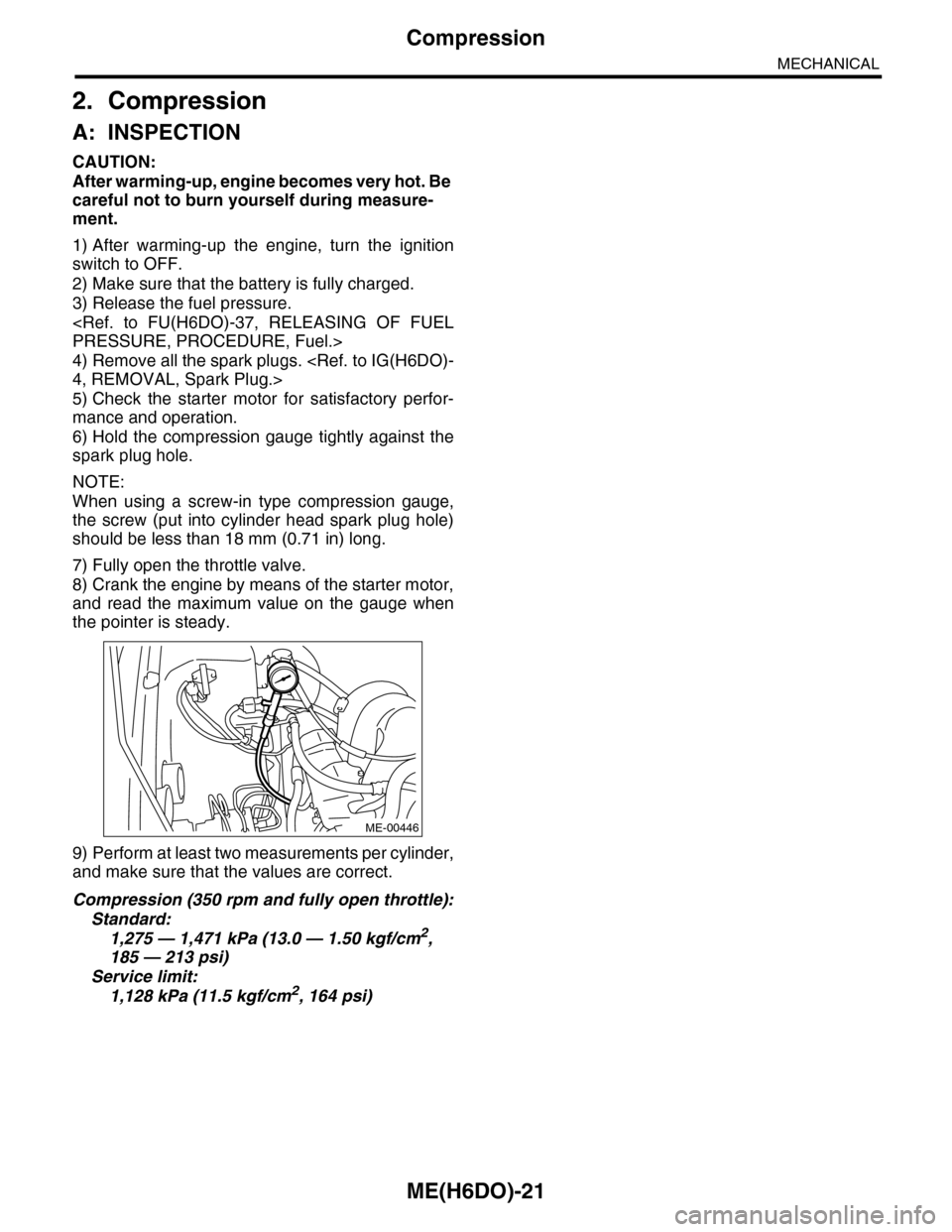
6) Hold the compression gauge tightly against the
spark plug hole.
NOTE:
When using a screw-in type compression gauge,
the screw (put into cylinder head spark plug hole)
should be less than 18 mm (0.71 in) long.
7) Fully open the throttle valve.
8) Crank the engine by means of the starter motor,
and read the maximum value on the gauge when
the pointer is steady.
9) Perform at least two measurements per cylinder,
and make sure that the values are correct.
Compression (350 rpm and fully open throttle):
Standard:
1,275 — 1,471 kPa (13.0 — 1.50 kgf/cm2,
185 — 213 psi)
Service limit:
1,128 kPa (11.5 kgf/cm2, 164 psi)
ME-00446
Page 1897 of 2453
ME(H6DO)-31
V-belt
MECHANICAL
9. V-belt
A: REMOVAL
1) Install the tool to belt tension adjuster assembly
installation bolt.
2) Rotate the tool clockwise and loosen the V-belt
to remove.
3) Remove the V-belt cover.
B: INSTALLATION
Install in the reverse order of removal.
C: INSPECTION
1) Replace the V-belt, if cracks, fraying or wear is
found.
2) Make sure that the V-belt automatic belt tension
indicator (A) is within the range (D).
(1) Power steering oil pump pulley
(2) Belt tension adjuster ASSY
(3) Crank pulley
(4) A/C compressor
(5) Belt idler
(6) Generator
ME-00473
(1)(6)
(4)
(5)(2)
(3)ME-00474
(A) Indicator
(B) Generator
(C) Power steering oil pump pulley
(D) Service limit
(B)
(A)
(D)
(C)
ME-00475
Page 1900 of 2453
ME(H6DO)-34
Engine Assembly
MECHANICAL
23) Remove the bolts which hold the vacuum pump
bracket to the engine and transmission, then re-
move the vacuum pump with the bracket.
24) Remove the bolts and nuts which hold lower
side of transmission to engine.
25) Remove the nuts which install front cushion
rubber onto front crossmember.
26) Lower the vehicle.
27) Separate the torque converter clutch from drive
plate.
(1) Remove the service hole plug.
(2) Remove the bolts which hold torque con-
verter clutch to drive plate.
(3) Remove other bolts while rotating the en-
gine using socket wrench.
28) Remove the pitching stopper.
ME-02660
ME-02662
ME-00485
(A) Service hole plug
(A)
ME-02445
ME-02446
Page 1902 of 2453
ME(H6DO)-36
Engine Assembly
MECHANICAL
B: INSTALLATION
1) Install the front cushion rubbers.
Tightening torque:
35 N·m (3.6 kgf-m, 25.8 ft-lb)
2) Position the engine in engine compartment and
align it with transmission.
NOTE:
Be careful not to damage adjacent parts or body
panels with crank pulley, oil level gauge, etc.
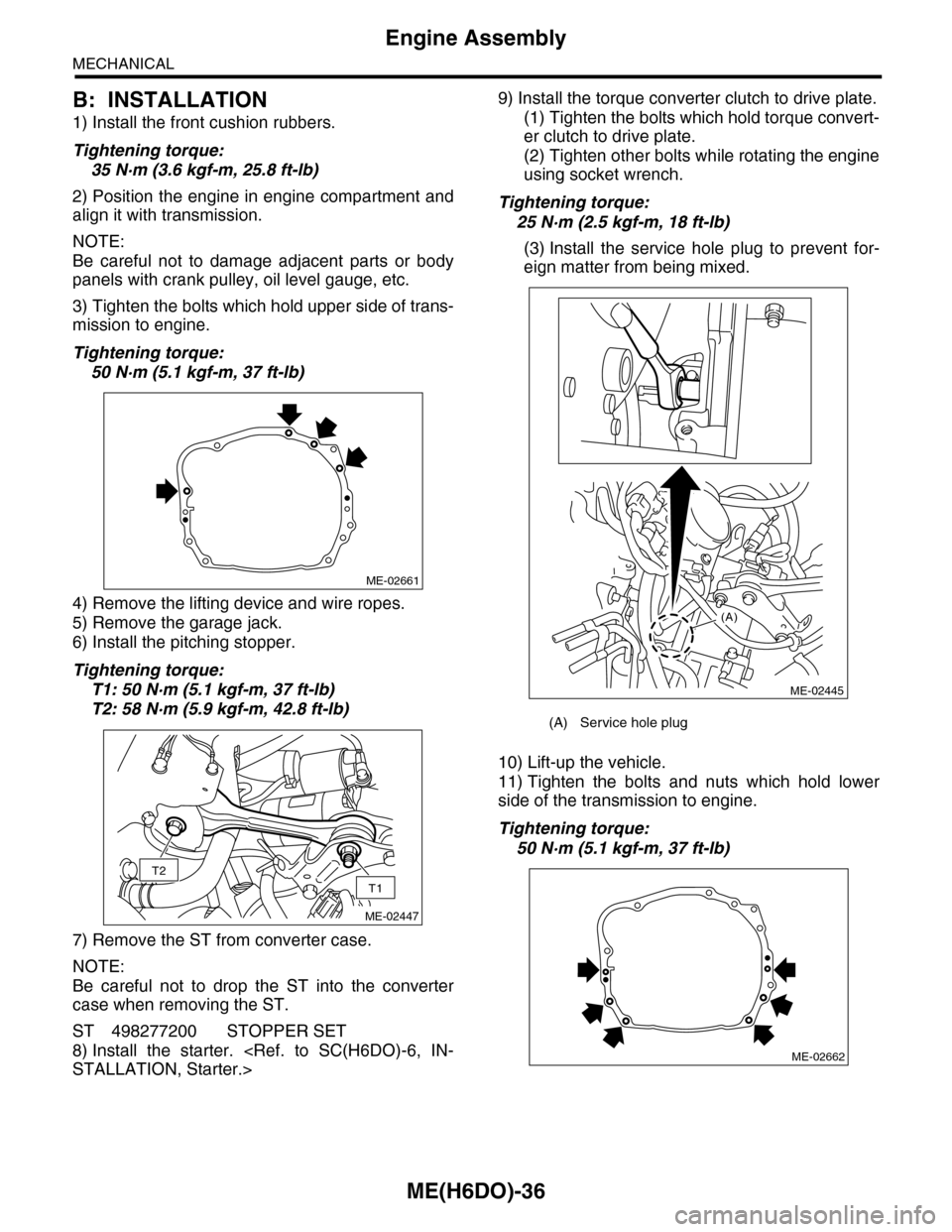
3) Tighten the bolts which hold upper side of trans-
mission to engine.
Tightening torque:
50 N·m (5.1 kgf-m, 37 ft-lb)
4) Remove the lifting device and wire ropes.
5) Remove the garage jack.
6) Install the pitching stopper.
Tightening torque:
T1: 50 N·m (5.1 kgf-m, 37 ft-lb)
T2: 58 N·m (5.9 kgf-m, 42.8 ft-lb)
7) Remove the ST from converter case.
NOTE:
Be careful not to drop the ST into the converter
case when removing the ST.
ST 498277200 STOPPER SET
8) Install the starter.
STALLATION, Starter.>
9) Install the torque converter clutch to drive plate.
(1) Tighten the bolts which hold torque convert-
er clutch to drive plate.
(2) Tighten other bolts while rotating the engine
using socket wrench.
Tightening torque:
25 N·m (2.5 kgf-m, 18 ft-lb)
(3) Install the service hole plug to prevent for-
eign matter from being mixed.
10) Lift-up the vehicle.
11) Tighten the bolts and nuts which hold lower
side of the transmission to engine.
Tightening torque:
50 N·m (5.1 kgf-m, 37 ft-lb)
ME-02661
T2
T1
ME-02447
(A) Service hole plug
(A)
ME-02445
ME-02662
Page 1929 of 2453
ME(H6DO)-63
Cylinder Block
MECHANICAL
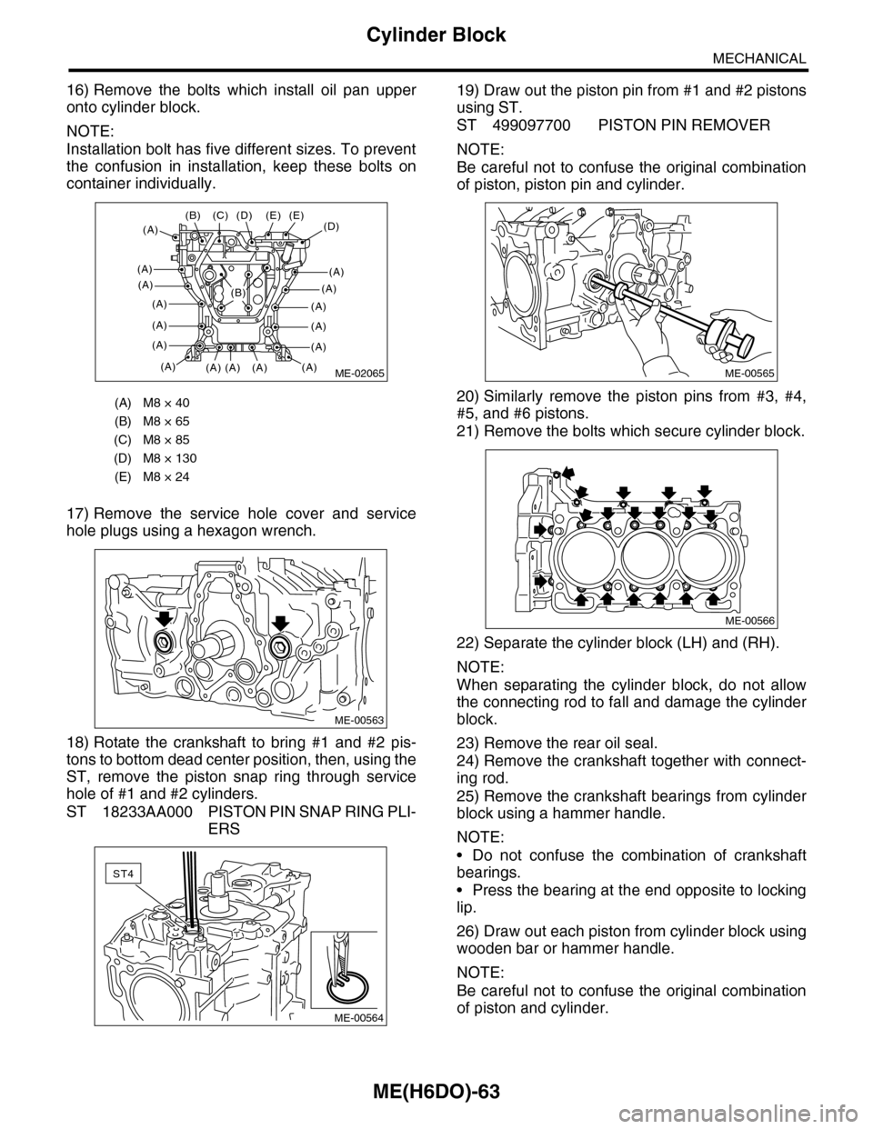
16) Remove the bolts which install oil pan upper
onto cylinder block.
NOTE:
Installation bolt has five different sizes. To prevent
the confusion in installation, keep these bolts on
container individually.
17) Remove the service hole cover and service
hole plugs using a hexagon wrench.
18) Rotate the crankshaft to bring #1 and #2 pis-
tons to bottom dead center position, then, using the
ST, remove the piston snap ring through service
hole of #1 and #2 cylinders.
ST 18233AA000 PISTON PIN SNAP RING PLI-
ERS
19) Draw out the piston pin from #1 and #2 pistons
using ST.
ST 499097700 PISTON PIN REMOVER
NOTE:
Be careful not to confuse the original combination
of piston, piston pin and cylinder.
20) Similarly remove the piston pins from #3, #4,
#5, and #6 pistons.
21) Remove the bolts which secure cylinder block.
22) Separate the cylinder block (LH) and (RH).
NOTE:
When separating the cylinder block, do not allow
the connecting rod to fall and damage the cylinder
block.
23) Remove the rear oil seal.
24) Remove the crankshaft together with connect-
ing rod.
25) Remove the crankshaft bearings from cylinder
block using a hammer handle.
NOTE:
•Do not confuse the combination of crankshaft
bearings.
•Press the bearing at the end opposite to locking
lip.
26) Draw out each piston from cylinder block using
wooden bar or hammer handle.
NOTE:
Be careful not to confuse the original combination
of piston and cylinder.
(A) M8 × 40
(B) M8 × 65
(C) M8 × 85
(D) M8 × 130
(E) M8 × 24
ME-02065
(D)(E)
(A)
(A)
(A)
(A)
(A)
(A)
(A)
(E)
(A)(A)(A)
(C)(B)
(A)
(D)
(A)
(A)
(A)
(A)
(A)
(B)
ME-00563
ST4
ME-00564
ME-00565
ME-00566
Page 1931 of 2453
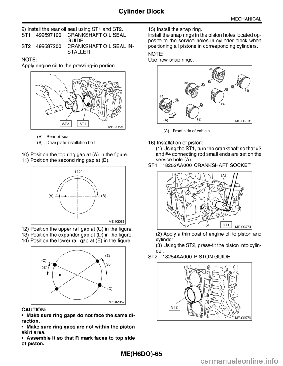
ME(H6DO)-65
Cylinder Block
MECHANICAL
9) Install the rear oil seal using ST1 and ST2.
ST1 499597100 CRANKSHAFT OIL SEAL
GUIDE
ST2 499587200 CRANKSHAFT OIL SEAL IN-
STALLER
NOTE:
Apply engine oil to the pressing-in portion.
10) Position the top ring gap at (A) in the figure.
11) Position the second ring gap at (B).
12) Position the upper rail gap at (C) in the figure.
13) Position the expander gap at (D) in the figure.
14) Position the lower rail gap at (E) in the figure.
CAUTION:
•Make sure ring gaps do not face the same di-
rection.
•Make sure ring gaps are not within the piston
skirt area.
•Assemble it so that R mark faces to top side
of piston.
15) Install the snap ring.
Install the snap rings in the piston holes located op-
posite to the service holes in cylinder block when
positioning all pistons in corresponding cylinders.
NOTE:
Use new snap rings.
16) Installation of piston:
(1) Using the ST1, turn the crankshaft so that #3
and #4 connecting rod small ends are set on the
service hole (A).
ST1 18252AA000 CRANKSHAFT SOCKET
(2) Apply a thin coat of engine oil to piston and
cylinder.
(3) Using the ST2, press-fit the piston into cylin-
der.
ST2 18254AA000 PISTON GUIDE
(A) Rear oil seal
(B) Drive plate installation bolt
ST2ST1
(A)
(B)
ME-00570
180˚
(A)(B)
ME-02066
25˚35˚(C)
(D)
(E)
ME-02067
(A) Front side of vehicle
(A)
#1
#2
#3
#4
#5
#6
ME-00573
ST1(A)
(A)
ME-00574
ST2
ME-00576