2009 SUBARU TRIBECA lift point
[x] Cancel search: lift pointPage 243 of 2453
EB-24
Rear Gate
EXTERIOR BODY PANELS
C: DISPOSAL
1. REAR GATE DAMPER STAY
CAUTION:
Gas is colorless, odorless, and harmless. How-
ever, gas pressure may spray cutting powder or
oil. Be sure to wear dust-resistant goggles.
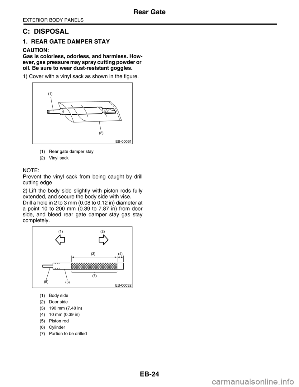
1) Cover with a vinyl sack as shown in the figure.
NOTE:
Prevent the vinyl sack from being caught by drill
cutting edge
2) Lift the body side slightly with piston rods fully
extended, and secure the body side with vise.
Drill a hole in 2 to 3 mm (0.08 to 0.12 in) diameter at
a point 10 to 200 mm (0.39 to 7.87 in) from door
side, and bleed rear gate damper stay gas stay
completely.
(1) Rear gate damper stay
(2) Vinyl sack
(1) Body side
(2) Door side
(3) 190 mm (7.48 in)
(4) 10 mm (0.39 in)
(5) Piston rod
(6) Cylinder
(7) Portion to be drilled
(1)
(2)
EB-00031
(3) (4)
(1)
(5)(6)
(7)
(2)
EB-00032
Page 928 of 2453

PS-48
Power Steering Fluid
POWER ASSISTED SYSTEM (POWER STEERING)
9. Power Steering Fluid
A: SPECIFICATION
B: INSPECTION
1) Check the power steering fluid for deterioration
or contamination. If the fluid is highly deteriorated
or contaminated, drain it and refill with new fluid.
2) Check the joints and units for oil leakage. If any
oil leaks are found, repair or replace the applicable
part.
3) Inspect the fluid level of reservoir tank with vehi-
cle on level surface and engine stopped.
If the level is at “MIN. ” point or below, add fluid to
keep the level in the specified range of the indica-
tor. If at “MAX. ” point or above, drain fluid by using
a syringe or the like.
(1) Check at power steering fluid temperature
20°C (68°F); read the fluid level on the “COLD”
side.
(2) Check at power steering fluid temperature
80°C (176°F); read the fluid level on the “HOT”
side.
C: REPLACEMENT
1) Lift-up the vehicle.
2) Remove the crossmember support.
3) Remove the pipe joint in the center of gearbox,
and connect the vinyl hose to the pipe and joint.
Wipe fluid off while turning the steering wheel.
4) Add the specified fluid to reservoir tank at “MAX”
level.
5) Continue to turn the steering wheel slowly from
lock to lock until the bubbles stop appearing on oil
surface while keeping the fluid at the level in the
Step 4).
6) If the steering wheel is turned in a low fluid level
condition, air will be sucked into the pipe. If sucked,
leave it about half an hour and then do the step 5)
again.
7) Start the engine and let it idle.
8) Continue to turn the steering wheel slowly from
lock to lock again until the bubbles stop appearing
on oil surface while keeping the fluid at the level in
Step 4).
Normally bubbles will stop appearing after turning
the steering wheel from lock to lock three times.
9) In case bubbles do not stop appearing in the
tank, leave it about half an hour and then do the
step 4) all over again.
10) Lower the vehicle, and then idle the engine.
11) Continue to turn the steering wheel from lock to
lock until the bubbles stop appearing and change of
the fluid level is within 3 mm (0.12 in).
12) In case the following happens, leave it about
half an hour and then do step 8) to 11) again.
(1) The fluid level changes over 3 mm (0.12 in).
(2) Bubbles remain on the upper surface of the
fluid.
(3) Grinding noise is generated from oil pump.
13) Check the fluid leakage after turning steering
wheel from lock to lock with engine running.
Recommended power steering fluid Manufacturer
AT F D E X R O N I I I o r e q u i v a l e n t
B.P.
CALTEX
CASTROL
MOBIL
SHELL
TEXACO
PS-00745
HOT MAXHOT MAINCOLD MAXCOLD MAIN
Page 945 of 2453

RS-12
Rear Shock Absorber
REAR SUSPENSION
6. Rear Shock Absorber
A: REMOVAL
1) Remove the strut cap of quarter trim.
2) Lift-up the vehicle, and then remove the rear
wheels.
3) Remove the nut and detach the rear stabilizer link.
4) Remove the bolts on the bottom side of the
shock absorber.
5) Detach the rear lateral link.
6) Remove the nuts of the shock absorber mount.
7) Remove the shock absorber.
B: INSTALLATION
NOTE:
•Be sure to use a new self-locking nut.
•Always tighten the stabilizer bushing in the state
where the vehicle is at curb weight and the wheels
are in full contact with the ground.
1) Install in the reverse order of removal.
CAUTION:
Attach so that the protrusion on the top of the
mount is pointed towards the front of the vehicle.
Tightening torque:
Refer to “COMPONENT” of “General Descrip-
tion” for the tightening torque.
2) Check the wheel alignment and adjust it if nec-
essary.
C: DISASSEMBLY
Refer to “Front Strut” for disassembly procedure.
D: ASSEMBLY
Refer to “Front Strut” for installation procedures.
E: INSPECTION
Refer to “Front Strut” for inspection procedures.
RS-00185
RS-00186
RS-00187
RS-00188
(1) Mount
(2) Protrusion por tion
(3) Front side of vehicle
Page 1113 of 2453
WT-7
Aluminum Wheel
WHEEL AND TIRE SYSTEM
3. Aluminum Wheel
A: REMOVAL
1) Apply the parking brake, and position select le-
ver to “P” or “LOW”.
2) Set the shop jacks or a lift to the specified points,
and support the vehicle with its wheels slightly con-
tacting the floor.
3) Loosen the wheel nuts.
4) Raise the vehicle until its wheels are off the
ground using the jack or a lift.
5) Remove the wheel nuts and wheels.
NOTE:
•When removing the wheels, be careful not to
damage the hub bolts.
•Place the wheels with their outer sides facing up-
ward to prevent wheels from being damaged.
B: INSTALLATION
1) Remove dirt from the mating surface of the
wheel and brake rotor.
2) Attach the wheel to the hub by aligning the wheel
bolt holes with the hub bolts.
3) Temporarily attach the wheel nuts to the hub
bolts. (In the case of aluminum wheels, use SUBA-
RU genuine wheel nuts for aluminum wheels.)
4) Tighten the nuts by hand, making sure the wheel
hub hole is aligned correctly to the guide portion of
hub.
5) Tighten the wheel nuts in a diagonal selection to
the specified torque. Use a wheel nut wrench.
Wheel nut tightening torque:
110 N·m (11.2 kgf-m, 81.1 ft-lb)
CAUTION:
•Tighten the wheel nuts in two or three steps
by gradually increasing the torque on opposing
nuts, until they reach the specified torque.
•Do not push the wrench by foot. Always use
both hands when tightening the nuts.
•Make sure the bolt, nut and the nut seating
surface of the wheel are free from oil.
6) If a wheel is removed for replacement or for re-
pair of a puncture, retighten the wheel nuts to the
specified torque after driving 1,000 km (600 miles).
C: INSPECTION
1) Deformation or damage to the rim may cause air
leakage. Check the rim flange for deformation,
cracks or damage, and repair or replace as neces-
sary.
2) Jack-up the vehicle until wheels clear the floor.
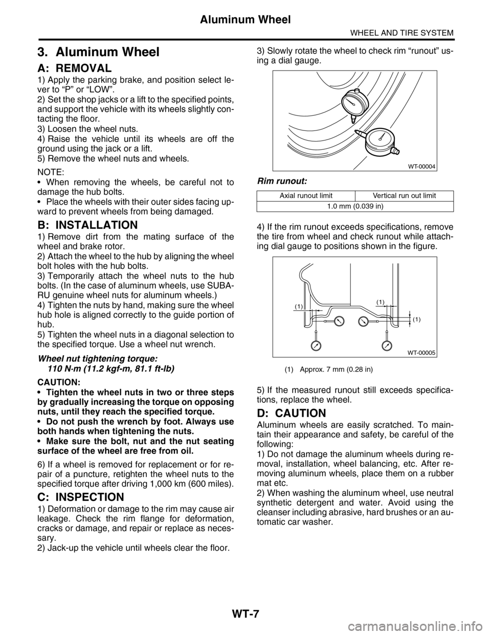
3) Slowly rotate the wheel to check rim “runout” us-
ing a dial gauge.
Rim runout:
4) If the rim runout exceeds specifications, remove
the tire from wheel and check runout while attach-
ing dial gauge to positions shown in the figure.
5) If the measured runout still exceeds specifica-
tions, replace the wheel.
D: CAUTION
Aluminum wheels are easily scratched. To main-
tain their appearance and safety, be careful of the
following:
1) Do not damage the aluminum wheels during re-
moval, installation, wheel balancing, etc. After re-
moving aluminum wheels, place them on a rubber
mat etc.
2) When washing the aluminum wheel, use neutral
synthetic detergent and water. Avoid using the
cleanser including abrasive, hard brushes or an au-
tomatic car washer.
Axial runout limit Vertical run out limit
1.0 mm (0.039 in)
(1) Approx. 7 mm (0.28 in)
WT-00004
WT-00005
(1)
(1)
(1)
Page 1138 of 2453
CO(H6DO)-19
Radiator
COOLING
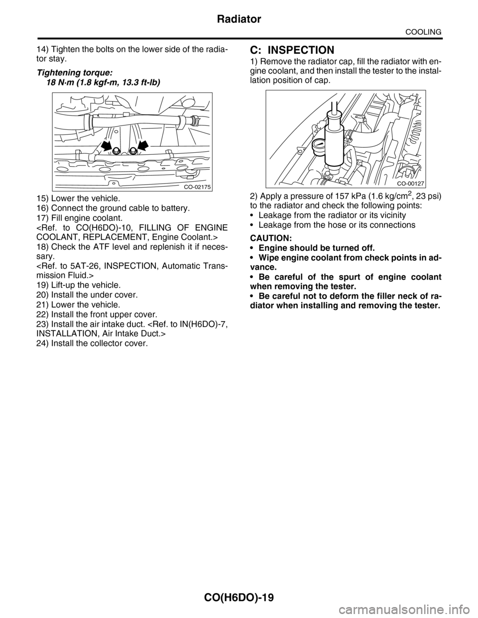
14) Tighten the bolts on the lower side of the radia-
tor stay.
Tightening torque:
18 N·m (1.8 kgf-m, 13.3 ft-lb)
15) Lower the vehicle.
16) Connect the ground cable to battery.
17) Fill engine coolant.
18) Check the ATF level and replenish it if neces-
sary.
19) Lift-up the vehicle.
20) Install the under cover.
21) Lower the vehicle.
22) Install the front upper cover.
23) Install the air intake duct.
24) Install the collector cover.
C: INSPECTION
1) Remove the radiator cap, fill the radiator with en-
gine coolant, and then install the tester to the instal-
lation position of cap.
2) Apply a pressure of 157 kPa (1.6 kg/cm2, 23 psi)
to the radiator and check the following points:
•Leakage from the radiator or its vicinity
•Leakage from the hose or its connections
CAUTION:
•Engine should be turned off.
•Wipe engine coolant from check points in ad-
vance.
•Be careful of the spurt of engine coolant
when removing the tester.
•Be careful not to deform the filler neck of ra-
diator when installing and removing the tester.
CO-02175CO-00127
Page 1166 of 2453
EN(H6DO)(diag)-5
General Description
ENGINE (DIAGNOSTICS)
3. General Description
A: CAUTION
1) Airbag system wiring harness is routed near the
ECM, main relay and fuel pump relay.
CAUTION:
•All airbag system wiring harnesses and con-
nectors are colored yellow. Do not use electri-
cal test equipment on these circuits.
•Be careful not to damage the airbag system
wiring harness when servicing the ECM, TCM,
main relay and fuel pump relay.
2) Never connect the battery in reverse polarity.
•The ECM will be destroyed instantly.
•The fuel injector and other parts will be dam-
aged.
3) Do not disconnect the battery terminals while the
engine is running.
A large counter electromotive force will be generat-
ed in the generator, and this voltage may damage
electronic parts such as ECM etc.
4) Before disconnecting the connectors of each
sensor and ECM, be sure to turn the ignition switch
to OFF. Perform the clear memory mode after con-
necting the connectors.
5) Poor contact has been identified as a primary
cause of this problem. Measure the voltage or re-
sistance of individual sensor or all electrical control
modules using a tapered pin with a diameter of less
than 0.64 mm (0.025 in). Do not insert the pin more
than 5 mm (0.20 in) into the part.
6) Remove the ECM from the located position after
disconnecting two cables on battery.
Otherwise, the ECM may be damaged.
CAUTION:
When replacing the ECM, be careful not to use
the wrong spec. ECM to avoid any damage on
the fuel injection system.
7) Connectors of each sensor in the engine com-
partment and the harness connectors on the en-
gine side and body side are all designed to be
waterproof. Even if the connectors are waterproof,
take care not to allow water to get into them when
washing the vehicle, or when servicing the vehicle
in rainy weather.
8) Use ECM mounting stud bolts as the grounding
point to chassis when measuring voltage and resis-
tance in the passenger compartment.
9) Use the engine ground terminal or engine as-
sembly as the grounding point to chassis when
measuring the voltage and resistance in engine
compartment.
10) Every MFI-related part is a precision part. Do
not drop them.
11) Observe the following cautions when installing
a radio in MFI equipped models.
CAUTION:
•The antenna must be kept as far apart as pos-
sible from control unit. (The ECM is located un-
der the steering column, inside of the
instrument panel lower trim panel.)
•The antenna feeder must be placed as far apart
as possible from the ECM and MFI harness.
•Carefully adjust the antenna for correct
matching.
•When mounting a large power type radio, pay
special attention to the three items mentioned
above.
•Incorrect installation of the radio may affect
the operation of ECM.
12) Release the pressure in the fuel system before
disconnecting the fuel hose. If engine starts during
this operation, run it until it stops.
13) For the model with ABS, the ABS warning light
may illuminate when performing driving test with
jacked-up or lifted-up condition, but this is not a
system malfunction. The reason for this is the
speed difference between the front and rear
wheels. After diagnosis of engine control system,
perform the ABS memory clear procedure of self-
diagnosis function.
B: INSPECTION
Before performing diagnostics, check the following
item which might affect engine problems.
1. BATTERY
1) Measure the battery voltage and specific gravity
of electrolyte.
Standard voltage: 12 V
Specific gravity: Above 1.260
2) Check the condition of the main and other fuses,
and harnesses and connectors. Also check for
proper grounding.
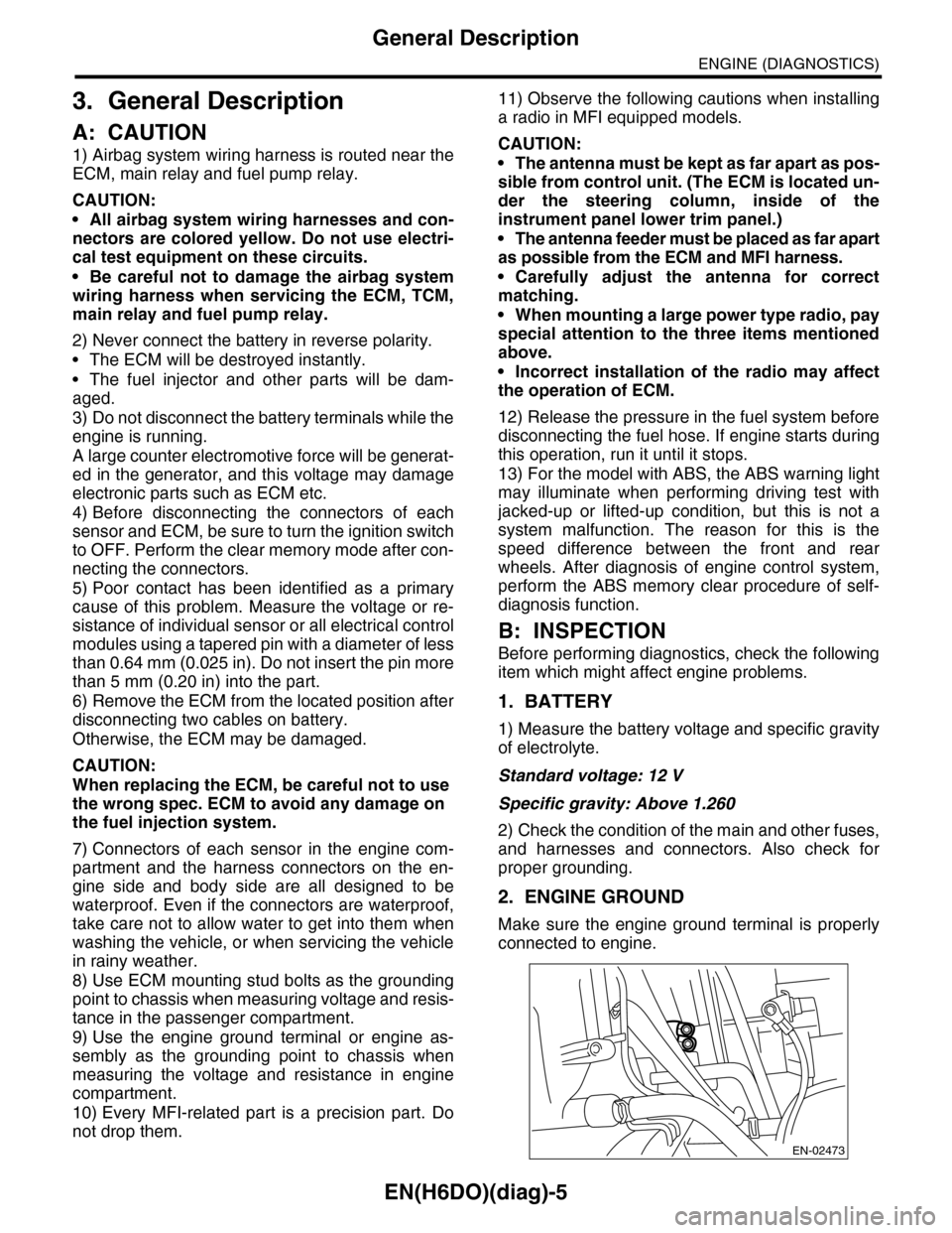
2. ENGINE GROUND
Make sure the engine ground terminal is properly
connected to engine.
EN-02473
Page 1880 of 2453
ME(H6DO)-14
General Description
MECHANICAL
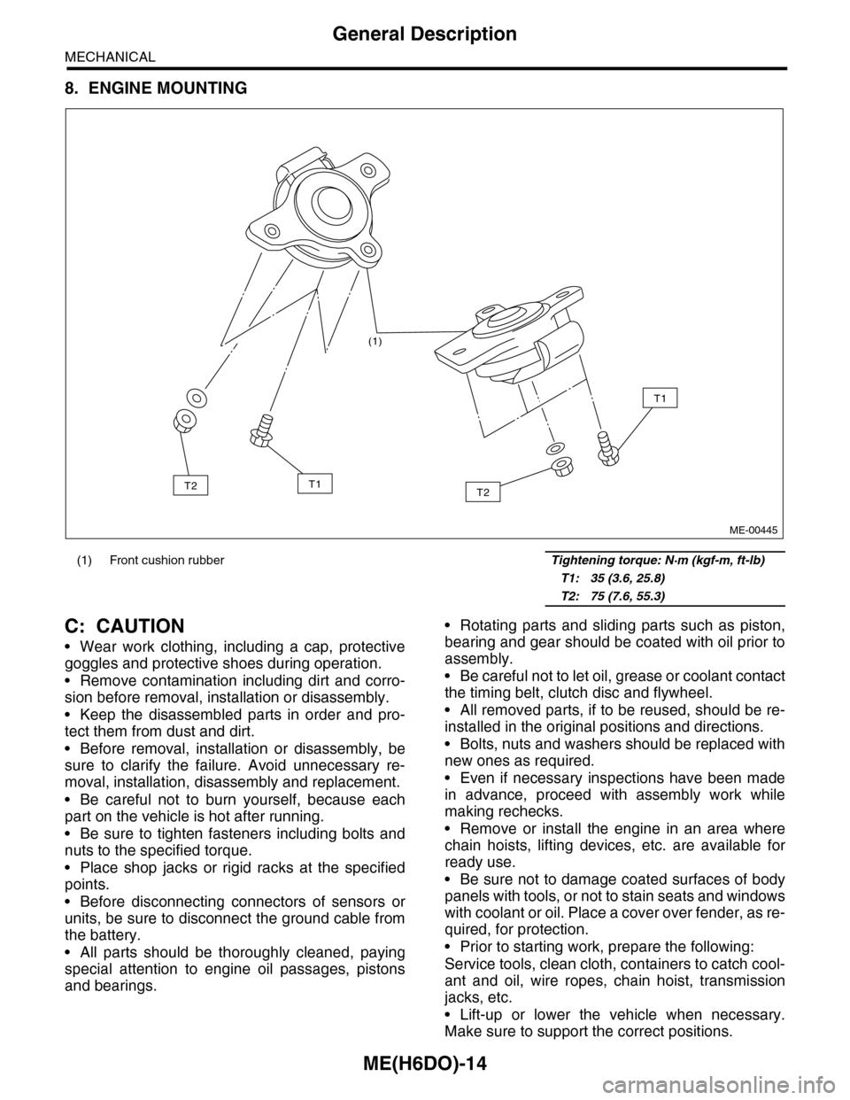
8. ENGINE MOUNTING
C: CAUTION
•Wear work clothing, including a cap, protective
goggles and protective shoes during operation.
•Remove contamination including dirt and corro-
sion before removal, installation or disassembly.
•Keep the disassembled parts in order and pro-
tect them from dust and dirt.
•Before removal, installation or disassembly, be
sure to clarify the failure. Avoid unnecessary re-
moval, installation, disassembly and replacement.
•Be careful not to burn yourself, because each
part on the vehicle is hot after running.
•Be sure to tighten fasteners including bolts and
nuts to the specified torque.
•Place shop jacks or rigid racks at the specified
points.
•Before disconnecting connectors of sensors or
units, be sure to disconnect the ground cable from
the battery.
•All parts should be thoroughly cleaned, paying
special attention to engine oil passages, pistons
and bearings.
•Rotating parts and sliding parts such as piston,
bearing and gear should be coated with oil prior to
assembly.
•Be careful not to let oil, grease or coolant contact
the timing belt, clutch disc and flywheel.
•All removed parts, if to be reused, should be re-
installed in the original positions and directions.
•Bolts, nuts and washers should be replaced with
new ones as required.
•Even if necessary inspections have been made
in advance, proceed with assembly work while
making rechecks.
•Remove or install the engine in an area where
chain hoists, lifting devices, etc. are available for
ready use.
•Be sure not to damage coated surfaces of body
panels with tools, or not to stain seats and windows
with coolant or oil. Place a cover over fender, as re-
quired, for protection.
•Prior to starting work, prepare the following:
Service tools, clean cloth, containers to catch cool-
ant and oil, wire ropes, chain hoist, transmission
jacks, etc.
•Lift-up or lower the vehicle when necessary.
Make sure to support the correct positions.
(1) Front cushion rubber Tightening torque: N·m (kgf-m, ft-lb)
T1: 35 (3.6, 25.8)
T2: 75 (7.6, 55.3)
(1)
T2
T1
T1T2
ME-00445
Page 2073 of 2453
5AT-57
ATF Cooler Pipe & Hose
AUTOMATIC TRANSMISSION
20.ATF Cooler Pipe & Hose
A: REMOVAL
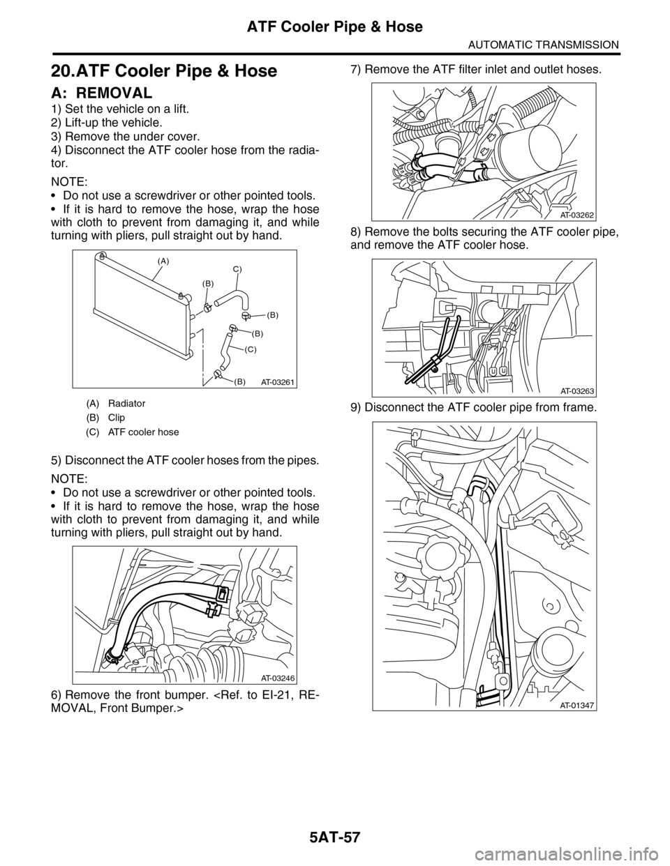
1) Set the vehicle on a lift.
2) Lift-up the vehicle.
3) Remove the under cover.
4) Disconnect the ATF cooler hose from the radia-
tor.
NOTE:
•Do not use a screwdriver or other pointed tools.
•If it is hard to remove the hose, wrap the hose
with cloth to prevent from damaging it, and while
turning with pliers, pull straight out by hand.
5) Disconnect the ATF cooler hoses from the pipes.
NOTE:
•Do not use a screwdriver or other pointed tools.
•If it is hard to remove the hose, wrap the hose
with cloth to prevent from damaging it, and while
turning with pliers, pull straight out by hand.
6) Remove the front bumper.
7) Remove the ATF filter inlet and outlet hoses.
8) Remove the bolts securing the ATF cooler pipe,
and remove the ATF cooler hose.
9) Disconnect the ATF cooler pipe from frame.(A) Radiator
(B) Clip
(C) ATF cooler hose
AT-03261
(A)
(B)
C)
(C)
(B)
(B)
(B)
AT-03246
AT-03262
AT-03263
AT-01347