2009 SUBARU TRIBECA air cleaner
[x] Cancel search: air cleanerPage 933 of 2453

PS-53
General Diagnostic Table
POWER ASSISTED SYSTEM (POWER STEERING)
3. INSPECTION OF CLEARANCE
This table lists various clearances that must be correctly adjusted to ensure the normal vehicle driving with-
out interfering noise, or any other faults.
Install locations Minimum allowance mm (in)
(1) Crossmember-to-Hose assembly 10 (0.39)
(2) Front frame side-to-Hose assembly 15 (0.59)
(3) Air bag sensor to cooler pipe assembly 10 (0.39)
(4) Air cleaner case-to-Suction hose 10 (0.39)
(5) VDCH/U to Reservoir tank bracket 10 (0.39)
(6) Air boots to Hose clip15 (0.59)
(7) Air boot-to-Hose assembly15 (0.59)
(8) Protector to Hose assembly10 (0.39)
(9) Intake manifold to Suction hose 10 (0.39)
(10) Intake manifold to hose assembly 10 (0.39)
(11) Air cleaner case to Cooler pipe joint block 5 (0.20)
(12) Chain cover to Cooler pipe joint block 20 (0.79)
(13) Oil pipe to Cooler pipe joint block 20 (0.79)
(14) Suction hose to Hose assembly 10 (0.39)
(15) Air boot to Reservoir tank10 (0.39)
(16) Brake pipe to Reservoir tank10 (0.39)
(17) Harness to Hose assembly10 (0.39)
(18) Relay box to Hose assembly15 (0.59)
(19) Bumper beam to Cooler pipe assembly 10 (0.39)
(20) Radiator bracket to Cooler pipe assembly 10 (0.39)
(21) ATF cooler to Cooler pipe assembly 10 (0.39)
(22) Undercover to cooler pipe assembly 10 (0.39)
(23) Protector to Hose assembly10 (0.39)
(24) Protector to Hose assembly15 (0.59)
(25) Return hose to Hose assembly 10 (0.39)
(26) Air cleaner case to Hose assembly 10 (0.39)
(27) Suction hose to Hose assembly 10 (0.39)
(28) Air cleaner case to Return hose 3 (0.12)
(29) Valve housing to DOJ12 (0.47)
(30) Valve housing to Crossmember 1 (0.04)
(31) Mount to Crossmember There must be no contact.
(32) Feed tube to Crossmember3 (0.12)
(33) Elbow to Crossmember3 (0.12)
(34) Cylinder pipe to Crossmember 3 (0.12)
(35) Feed tube to Exhaust pipe18 (0.71)
(36) Tie-rod end to Brake dust cover 2.5 (0.10)
(37) Coupling rubber to AT level gage 10 (0.39)
(38) Yoke to Brake booster5 (0.20)
Page 1457 of 2453
EN(H6DO)(diag)-296
Diagnostic Procedure with Diagnostic Trouble Code (DTC)
ENGINE (DIAGNOSTICS)
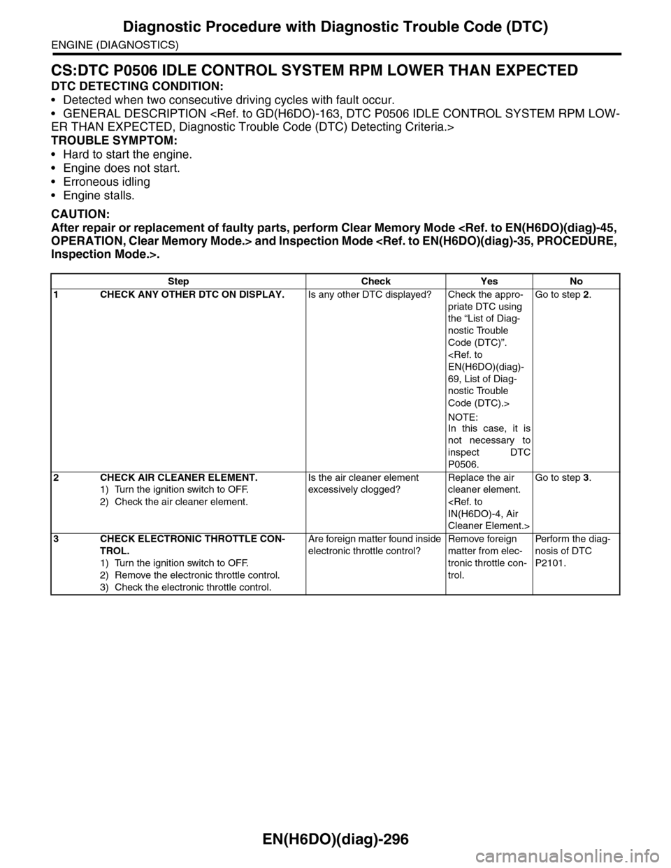
CS:DTC P0506 IDLE CONTROL SYSTEM RPM LOWER THAN EXPECTED
DTC DETECTING CONDITION:
•Detected when two consecutive driving cycles with fault occur.
•GENERAL DESCRIPTION
TROUBLE SYMPTOM:
•Hard to start the engine.
•Engine does not start.
•Erroneous idling
•Engine stalls.
CAUTION:
After repair or replacement of faulty parts, perform Clear Memory Mode
Step Check Yes No
1CHECK ANY OTHER DTC ON DISPLAY.Is any other DTC displayed? Check the appro-
priate DTC using
the “List of Diag-
nostic Trouble
Code (DTC)”.
69, List of Diag-
nostic Trouble
Code (DTC).>
NOTE:
In this case, it is
not necessary to
inspect DTC
P0506.
Go to step 2.
2CHECK AIR CLEANER ELEMENT.
1) Turn the ignition switch to OFF.
2) Check the air cleaner element.
Is the air cleaner element
excessively clogged?
Replace the air
cleaner element.
Cleaner Element.>
Go to step 3.
3CHECK ELECTRONIC THROTTLE CON-
TROL.
1) Turn the ignition switch to OFF.
2) Remove the electronic throttle control.
3) Check the electronic throttle control.
Are foreign matter found inside
electronic throttle control?
Remove foreign
matter from elec-
tronic throttle con-
trol.
Per fo r m th e di ag -
nosis of DTC
P2101.
Page 1573 of 2453
FU(H6DO)-12
Intake Manifold
FUEL INJECTION (FUEL SYSTEMS)
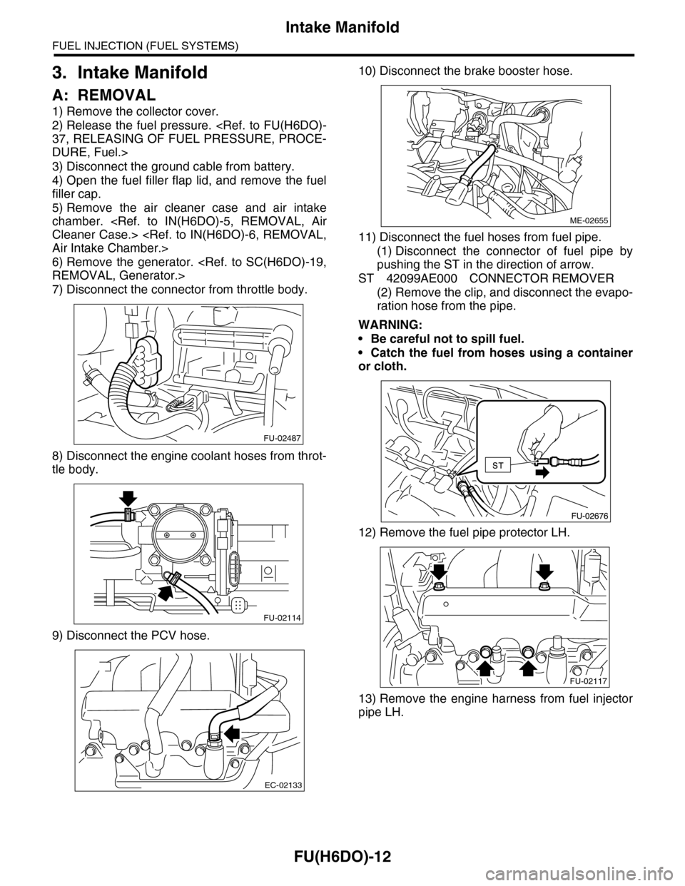
3. Intake Manifold
A: REMOVAL
1) Remove the collector cover.
2) Release the fuel pressure.
DURE, Fuel.>
3) Disconnect the ground cable from battery.
4) Open the fuel filler flap lid, and remove the fuel
filler cap.
5) Remove the air cleaner case and air intake
chamber.
6) Remove the generator.
7) Disconnect the connector from throttle body.
8) Disconnect the engine coolant hoses from throt-
tle body.
9) Disconnect the PCV hose.
10) Disconnect the brake booster hose.
11) Disconnect the fuel hoses from fuel pipe.
(1) Disconnect the connector of fuel pipe by
pushing the ST in the direction of arrow.
ST 42099AE000 CONNECTOR REMOVER
(2) Remove the clip, and disconnect the evapo-
ration hose from the pipe.
WARNING:
•Be careful not to spill fuel.
•Catch the fuel from hoses using a container
or cloth.
12) Remove the fuel pipe protector LH.
13) Remove the engine harness from fuel injector
pipe LH.
FU-02487
FU-02114
EC-02133
ME-02655
FU-02117
Page 1576 of 2453
FU(H6DO)-15
Intake Manifold
FUEL INJECTION (FUEL SYSTEMS)
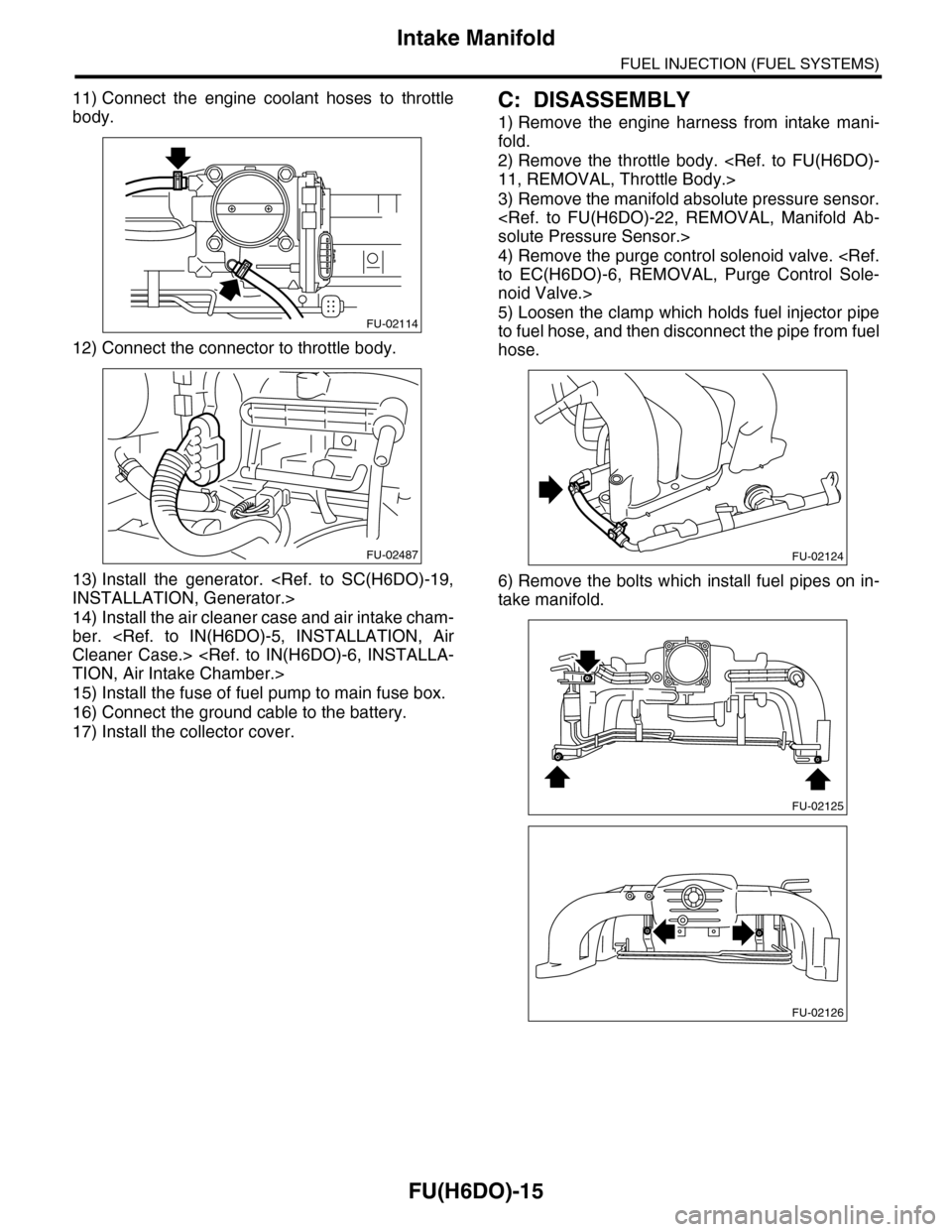
11) Connect the engine coolant hoses to throttle
body.
12) Connect the connector to throttle body.
13) Install the generator.
14) Install the air cleaner case and air intake cham-
ber.
15) Install the fuse of fuel pump to main fuse box.
16) Connect the ground cable to the battery.
17) Install the collector cover.
C: DISASSEMBLY
1) Remove the engine harness from intake mani-
fold.
2) Remove the throttle body.
3) Remove the manifold absolute pressure sensor.
4) Remove the purge control solenoid valve.
noid Valve.>
5) Loosen the clamp which holds fuel injector pipe
to fuel hose, and then disconnect the pipe from fuel
hose.
6) Remove the bolts which install fuel pipes on in-
take manifold.
FU-02114
FU-02487FU-02124
FU-02125
FU-02126
Page 1585 of 2453
FU(H6DO)-24
Fuel Injector
FUEL INJECTION (FUEL SYSTEMS)
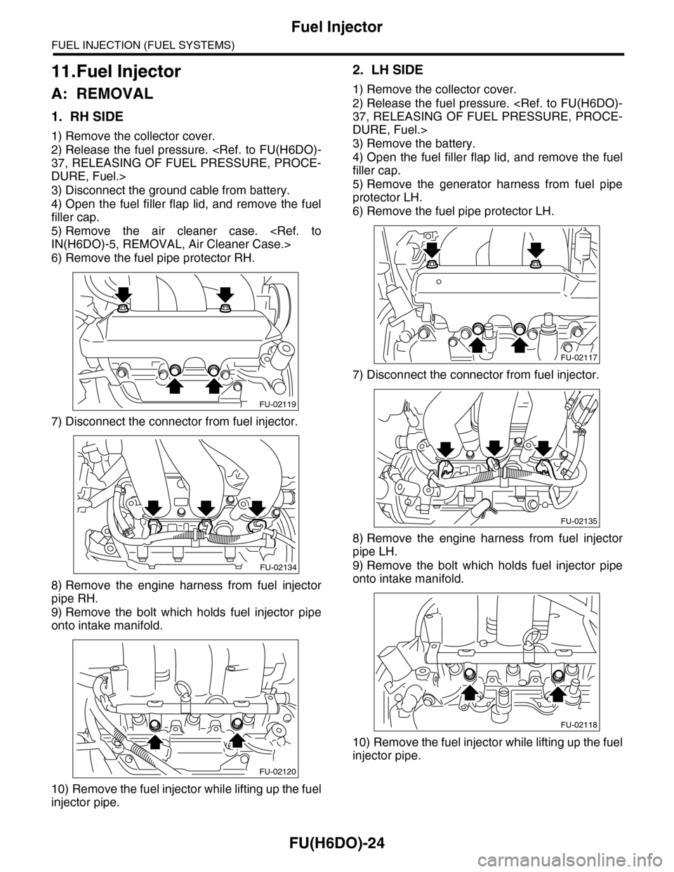
11.Fuel Injector
A: REMOVAL
1. RH SIDE
1) Remove the collector cover.
2) Release the fuel pressure.
DURE, Fuel.>
3) Disconnect the ground cable from battery.
4) Open the fuel filler flap lid, and remove the fuel
filler cap.
5) Remove the air cleaner case.
6) Remove the fuel pipe protector RH.
7) Disconnect the connector from fuel injector.
8) Remove the engine harness from fuel injector
pipe RH.
9) Remove the bolt which holds fuel injector pipe
onto intake manifold.
10) Remove the fuel injector while lifting up the fuel
injector pipe.
2. LH SIDE
1) Remove the collector cover.
2) Release the fuel pressure.
DURE, Fuel.>
3) Remove the battery.
4) Open the fuel filler flap lid, and remove the fuel
filler cap.
5) Remove the generator harness from fuel pipe
protector LH.
6) Remove the fuel pipe protector LH.
7) Disconnect the connector from fuel injector.
8) Remove the engine harness from fuel injector
pipe LH.
9) Remove the bolt which holds fuel injector pipe
onto intake manifold.
10) Remove the fuel injector while lifting up the fuel
injector pipe.
FU-02119
FU-02134
FU-02120
FU-02117
FU-02135
FU-02118
Page 1839 of 2453
IG(H6DO)-4
Spark Plug
IGNITION
2. Spark Plug
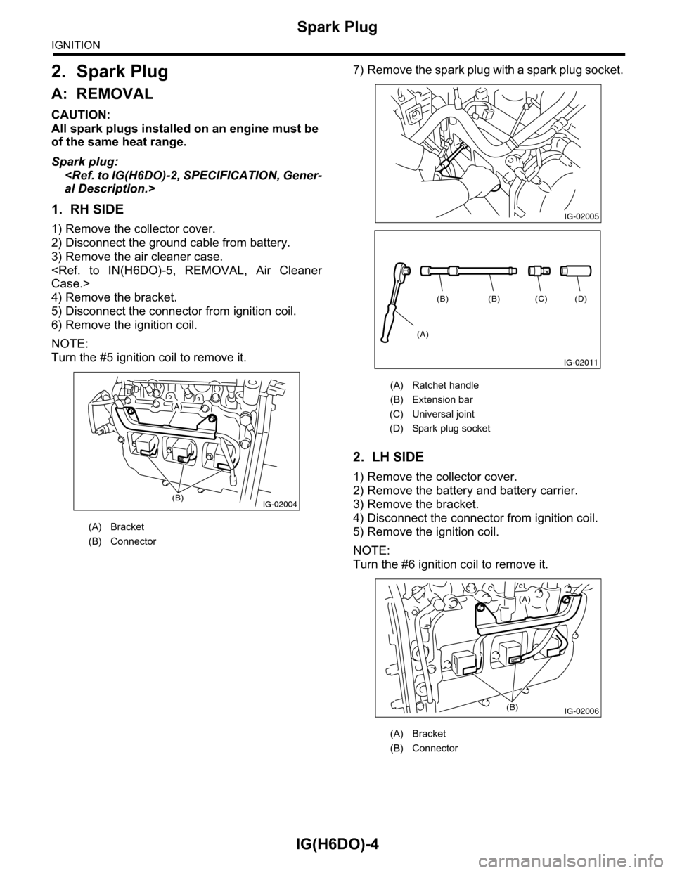
A: REMOVAL
CAUTION:
All spark plugs installed on an engine must be
of the same heat range.
Spark plug:
1. RH SIDE
1) Remove the collector cover.
2) Disconnect the ground cable from battery.
3) Remove the air cleaner case.
4) Remove the bracket.
5) Disconnect the connector from ignition coil.
6) Remove the ignition coil.
NOTE:
Turn the #5 ignition coil to remove it.
7) Remove the spark plug with a spark plug socket.
2. LH SIDE
1) Remove the collector cover.
2) Remove the battery and battery carrier.
3) Remove the bracket.
4) Disconnect the connector from ignition coil.
5) Remove the ignition coil.
NOTE:
Turn the #6 ignition coil to remove it.
(A) Bracket
(B) Connector
IG-02004(B)
(A)
(A) Ratchet handle
(B) Extension bar
(C) Universal joint
(D) Spark plug socket
(A) Bracket
(B) Connector
IG-02005
(D)(C)(B)(B)
(A)
IG-02011
IG-02006
(A)
(B)
Page 1841 of 2453
IG(H6DO)-6
Spark Plug
IGNITION
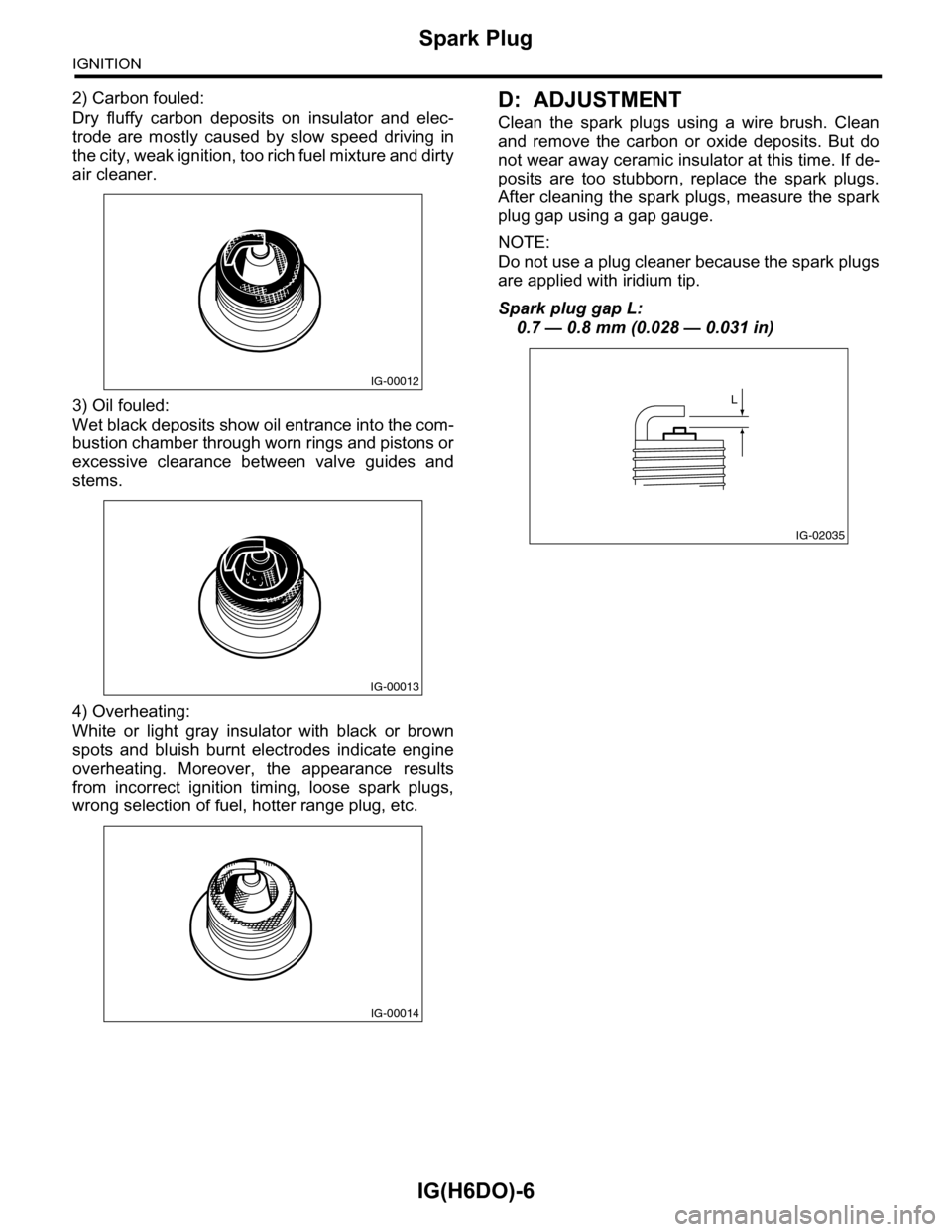
2) Carbon fouled:
Dry fluffy carbon deposits on insulator and elec-
trode are mostly caused by slow speed driving in
the city, weak ignition, too rich fuel mixture and dirty
air cleaner.
3) Oil fouled:
Wet black deposits show oil entrance into the com-
bustion chamber through worn rings and pistons or
excessive clearance between valve guides and
stems.
4) Overheating:
White or light gray insulator with black or brown
spots and bluish burnt electrodes indicate engine
overheating. Moreover, the appearance results
from incorrect ignition timing, loose spark plugs,
wrong selection of fuel, hotter range plug, etc.
D: ADJUSTMENT
Clean the spark plugs using a wire brush. Clean
and remove the carbon or oxide deposits. But do
not wear away ceramic insulator at this time. If de-
posits are too stubborn, replace the spark plugs.
After cleaning the spark plugs, measure the spark
plug gap using a gap gauge.
NOTE:
Do not use a plug cleaner because the spark plugs
are applied with iridium tip.
Spark plug gap L:
0.7 — 0.8 mm (0.028 — 0.031 in)
IG-00012
IG-00013
IG-00014
IG-02035
L
Page 1845 of 2453
IN(H6DO)-3
General Description
INTAKE (INDUCTION)
B: CAUTION
•Wear work clothing, including a cap, protective
goggles and protective shoes during operation.
•Remove contamination including dirt and corro-
sion before removal, installation or disassembly.
•Keep the disassembled parts in order and pro-
tect them from dust and dirt.
•Before removal, installation or disassembly, be
sure to clarify the failure. Avoid unnecessary re-
moval, installation, disassembly and replacement.
•Be careful not to burn yourself, because each
part on the vehicle is hot after running.
•Be sure to tighten fasteners including bolts and
nuts to the specified torque.
•Place shop jacks or rigid racks at the specified
points.
•Before disconnecting connectors of sensors or
units, be sure to disconnect the ground cable from
the battery.
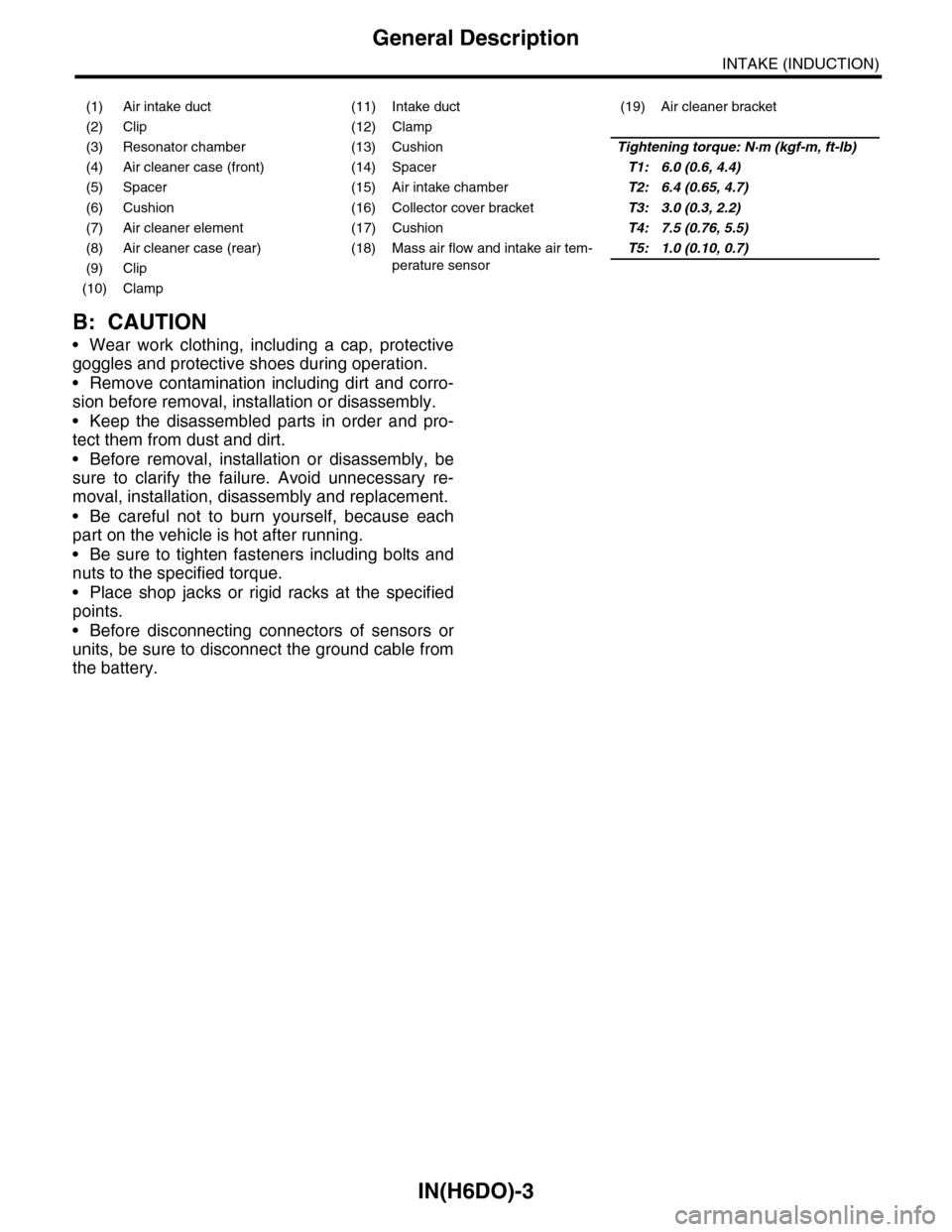
(1) Air intake duct (11) Intake duct (19) Air cleaner bracket
(2) Clip (12) Clamp
(3) Resonator chamber (13) CushionTightening torque: N·m (kgf-m, ft-lb)
(4) Air cleaner case (front) (14) SpacerT1: 6.0 (0.6, 4.4)
(5) Spacer (15) Air intake chamberT2: 6.4 (0.65, 4.7)
(6) Cushion (16) Collector cover bracketT3: 3.0 (0.3, 2.2)
(7) Air cleaner element (17) CushionT4: 7.5 (0.76, 5.5)
(8) Air cleaner case (rear) (18) Mass air flow and intake air tem-
perature sensor
T5: 1.0 (0.10, 0.7)
(9) Clip
(10) Clamp